Design Model of a Hydrodynamic Towing Tank for Colombia
Modelo de diseño de un canal de ensayos hidrodinámicos para Colombia
Wilson Toncel Zuleta1
Jairo Cabrera T.2
Abstract
This paper develops a methodology for the design of a hydrodynamic ship tank model and its main components considering the current and projected needs of the maritime and river industry of Colombia. Besides allowing resistance, seakeeping, and maneuvering model tests with international standards.
Key words: Ship model hydrodynamic tank, wave generation, PMM, ship model scale
Resumen
En el presente trabajo se desarrolla una metodología de dimensionamiento para un canal de ensayos hidrodinámicos y sus principales componentes considerando las necesidades actuales y proyecciones del sector marítimo y fluvial de Colombia. Además de permitir realizar ensayos de resistencia al avance, comportamiento en olas y de maniobras con estándares de confiabilidad internacional.
Palabras claves: Canal de ensayos, hidrodinámica, generación y amortiguación de olas, ensayos modelos a escala de buques
Date Received: December 14th, 2013 - Fecha de recepción: 14 de Diciembre de 2012
Date Accepted: March 2nd, 2013 - Fecha de aceptación: 2 de Marzo de 2013
________________________
1 Universidad Tecnológica de Bolívar. Faculty of Engineering, Department of Mechanics and Mechatronics. Cartagena, Colombia. e-mail: wilson.toncel@gmail.com
2 Universidad Tecnológica de Bolívar. Faculty of Engineering, Department of Mechanics and Mechatronics. Cartagena, Colombia. e-mail: jcabrera@unitecnologia.edu.co
............................................................................................................................................................
Introduction
Colombia has broad coastlines and hydrographic basins that have granted it great diversity and hydric richness; its seacoasts and rivers are potential commercial and transportation paths currently unappreciated, perhaps without knowing that using this mode of transportation may signifi cantly reduce logistics costs. In spite of having coastlines on two oceans, the development of the naval industry in Colombia has been limited due to lack of ideas and proposals that push an eff ective start to this fi eld.
Colombia’s strategic location off ers the advantage of availing of the richness of riverine and maritime resources, only requiring an initiative to adequately use said geographically prized richness.
Appropriate development of the naval industry in Colombia will permit addressing the growing demand for mobility presented in these moments of industrial expansion.
Due to the aforementioned, it becomes important for the development of the naval area in Colombia to have a Hydrodynamic test tank and which can be defi ned as a physical laboratory in which tests are developed with models of scaled-down geometrically similar maritime systems, to predict the behavior of said designs under specifi c conditions in the diff erent situations at sea.
A broad variety of channels for hydrodynamic tests exists, depending mainly on the purpose or types of tests destined for execution.
Among the channels with captive models there are those aimed at evaluating pure drag and having suffi cient breadth may, likewise, run maneuverability tests for which a planar motion mechanism (PMM) is required.
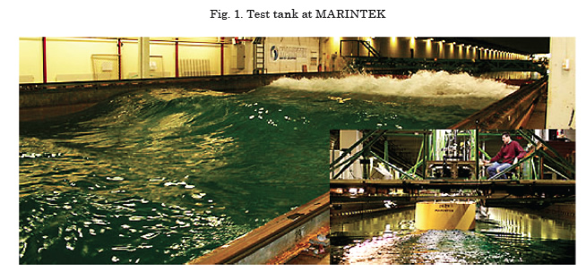
Other channels are destined to evaluating the behavior against the environmental conditions of vessels and/or maritime platforms for which specifi c components are necessary as wave generators and dampers, besides equipment associated with the acquisition and treatment of data. Fig. 1 shows the hydrodynamic test tank in MARINTEK (Norway).
This work is aimed at the development of a towing tank sizing model, which – likewise – permits analyzing behavior in waves and of maneuverability, considering the current and projected needs of the Colombian naval and riverine industry.
Use of test tanks in ship design
During its early days, naval design was predominated by empirical tendencies; it may be said that the first studies using scale models were by Leonardo Da Vinci (Alaez J, 1953), after him, followed in the progress of said field, researchers like D’Alembert, John Bernoulli (Alaez & Roberston, 1965), and John Smeaton (Dos Santos & Michima, 2007) among many others.
Since then, naval design has, thus, evolved permitting greater efficiency in each of the processes related to such. Naval design currently has numerous computer tools that, through good management, could provide an approach of the behavior expected in the vessels; however, much is still needed for these procedures to be completely reliable, which is why tanks are used to perform different tests.
From these tanks diverse maneuvers may be executed with which we can obtain values and interpret such to predict the behavior of a particular design. The difference with the computational models lies in the approximation to the real behavior, carrying out good practices with adequate equipment.
The sizing model proposed for the test tank presents the general and specific characteristics of a towtype tank, as well as all its necessary component equipment, according to the tow test requirements, behavior on waves, and maneuverability.
Naval construction in Colombia
According to a recent study of the shipyard sector in Colombia conducted by Universidad Tecnologica de Bolivar, Universidad del Norte, Universidad del Rosario, and COTECMAR in 2012, this activity is concentrated thus: Caribbean region (Cartagena, Barranquilla, and Santa Marta) with 55% of the total; Antioquia (Medellín, Envigado, and Turbo) participating with 18%, the Pacific Coast (Cali, Buenaventura, and Bahía Solano) participating with 15%; followed by Cundinamarca with 12% of the total.
The same study reveals that the vessels with the greatest demand are:
• Inflatable Pleasure Boats
• Boats
• Canoes
• Skiffs
• Water Bikes
• Barges
• Tugboats
• Fast Patrol Boats
• Heavy Patrol Boats
• Patrol-Type Ship
COTECMAR1 is among the most highlighted companies in the sector, being the main shipyard in Colombia and which has been waging on the innovation management process, promoting the culture of naval design and construction, achieving the development of patrol-type boats, landing ships, and fast boats, among others.
Currently, COTECMAR is working on the development of a strategic surface platform (SSP) that will substitute the current fleet of frigates, major defense ships in the country.
Development of the hydrodynamic tank proposed in this work will permit optimizing disciplines of the design process, especially those related with the calculation of drag, behavior on waves, and maneuverability with sufficient capacity to meet the current and projected demand of the SSP project and other medium and small-sized ships requiring design in the country.
Sizing model
Determination of the adequate dimensions for a hydrodynamic test tank is closely related to the geometric characteristics of its components and to the dimensions of the scale models to be evaluated.
The ITTC2 is the regulatory entity of the practices mentioned, accrediting institutions that comply with the minimum requirements for the reliable execution of tests and standardizing the procedures to be followed in each of the practices.
The elements participating in the execution of tests for the hydrodynamic tank proposed are:
• Scale models
• Tow truck - PMM
• Wave generator
• Wave absorber
Of the previous components, the scale models play the most relevant role in the whole tank sizing process; based on these, the following will be the defined characteristics of wave generation, dimensions of wave absorption beaches, and PMM tow rate and acceleration.
From the dimensions of the models, the reference scales are defined in the different tests, thus, the main dimensions of the tank have a direct relationship with the geometric characteristics of the models to evaluate.
In carrying out the sizing model of the test tank a data bank was required, contemplating the characteristics of the types of ships to be tested.
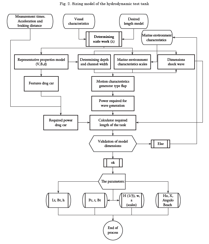
Fig. 2 shows the sizing model of the tank and its different components. As input values of the model, the geometric characteristics of the scale model, conditions at sea to recreate, and the parameters of test execution are necessary, thus, obtaining the dimensional value of each of its basic components.
Taking as reference the parameters of the tank’s constitutive elements, we managed to determine from equations 1 (Ueno & Nagamatsu, 1971) and 2 (citation VID12 \l 9226 | (Vidal Bosch & Barberá Fernández, 2012) its appropriate dimensions: length, depth, and breadth.
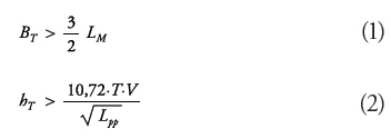
Where:
Lpp: Length between perpendiculars
BT: Tank width
LM: Length of model
hT: Tank depth
T: Draft of model
V: Tow rate
Scale model
As previously mentioned, scale models represent parameters of special importance to size the tank and its components, as observed in Fig. 2.
For tank sizing, we must have the initial value of this parameter to start the process; at the end we validate if the values obtained, with the scales worked, comply with the functional restrictions for each test proposed; otherwise, the necessary iterations must be conducted to achieve the respective adjustments.
Determination of the magnitudes of the models leads to the use of similarity laws; for this case it will be geometric similarity, although there are also kinetic and dynamic similarities.
The geometric similarity proposes that the relationship between the “length” (length, breadth, draft, etc.,), Lg, of a ship at real scale and the “length” of the scale model, Lm, must be constant; this relationship is called scale factor and it is designated with the letter λ, according to equation 3.
![]()
By using λ we will manage to maintain similarities regarding conditions at sea and velocities.
PMM Sizing
The sizing process of the Planar Motion Mechanism (PMM) or tow truck refers to the calculation of the power required to propel the structure under the parameters desired.
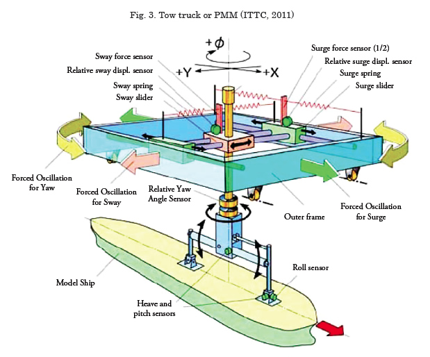
Fig. 3 shows a sample PMM structure. This component is closely related to tow, vertical motion, and maneuverability tests. Its calculation is made based on the nature of the motion in each of its stages, as noted in Fig. 4. The process starts with the determination of the forces present for the zones of constant acceleration, calculated according to equation 4.
![]()
Where:
Fa: forces in the acceleration zone (N)
Fra: air resistance force:
Where:
Ff : frictional force on the four wheels
FIM: drag force induced by the model
mca: estimated mass of the tow truck (Kg)
a: acceleration (m/s2)
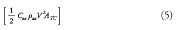
The determination of power results from the multiplication of the sum of forces and the velocity to be reached. In the constant velocity zone, the forces would be evaluated through equation 6.
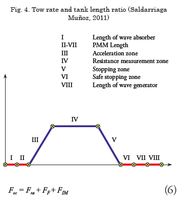
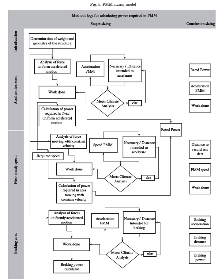
Upon calculating the power required in the constant velocity zone, we determine the required nominal power as the mathematical sum of the previously mentioned. Fig. 5 details the complete methodology of the calculation.
Wave Generator
The wave generator does not have the simple purpose of creating arbitrary disturbances in the work fluid; rather, its final purpose is that of reproducing the sea state under different conditions, from the most passive to those of greater magnitude.
To design a wave generator, we must consider the relationship between wave height and the displacement of the wave generator actuator; this ratio is given by the following equation (Dalrymple & Dean, 1984):
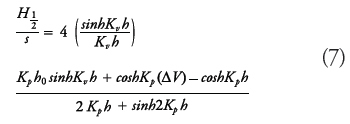
Where:
H1/3: wave height
S: Course or “stroke”
Kp:K: wave number (2π/Lw)
Lw: wave length
h: total depth of tank
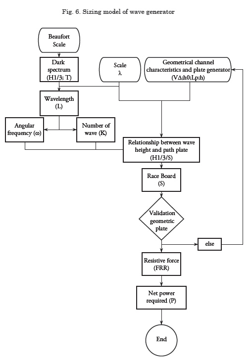
By calculating this equation, we can determine the stroke the generation plate must have, becoming only a geometric problem the determination of the angles of motion, the minimum length required for the tilting plate, see Fig. 6.
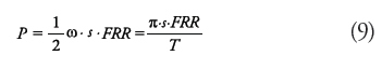
The resistive forces (FRR) are obtained through calculating the momentum on the rotation axis (Gonzalez Alvarez Campana, 1988), which varies in function of the plate height and its motion according to equation 8.
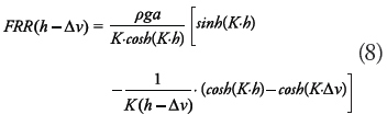
Power was determined according to equation 9.
Wave absorption beach
The wave absorption beach is a damping element of the waves present in the tank. Its function is to dissipate the energy produced by waves, avoiding disturbance of the simulated environment by the reflection of the waves and interference in recording the movements of the model, see Fig. 7.
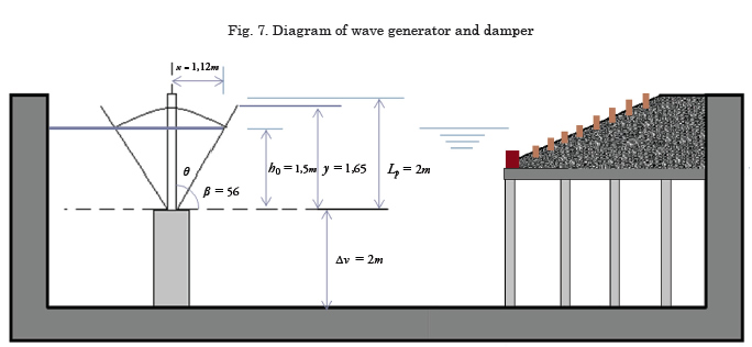
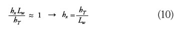
Sizing of this component, its length (x) and height (hx) may be evaluated from Svendsen and Jonsson’s equation, where (hT) is the tank’s depth and (Lw) the length of the wave (Saldarriaga Muñoz, 2011):
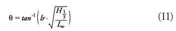
Based on the Irribaren ratios (Saldarriaga Muñoz, 2011), we may calculate the angle of the absorption beach:
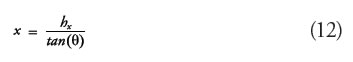
And through simple geometry, calculate the beach length required:
Application of the model
analysis of the global tendencies for the size of the model was considered as a starting point; a value of up to 4 m is considered and a CPV3 -type vessel is selected, which serves as reference for the development of the model.
By following the stages of the model proposed, we achieve the sizing of the tank and its components, obtaining the data presented by the following:
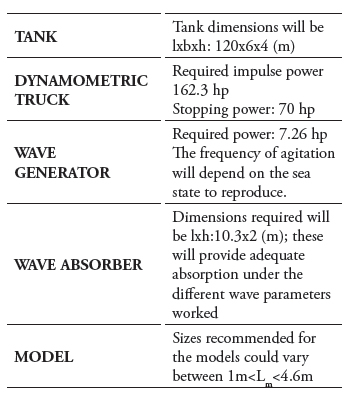
The test tank, product of the application of the model, can reliably run tests for a broad range of small ships, including maritime and riverine patrol boats, multi-purpose tugboats, and even frigatetype ships from the Strategic Surface Platform project.
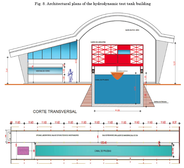
Fig. 8 shows the preliminary architectural project of the hydrodynamic test tank proposed for Colombia.
Conclusions
After analyzing the critical variables in sizing a hydrodynamic tank, equally covering current and projected needs of the naval industry in Colombia, it was possible to methodologically establish the preliminary dimensions of a tow test tank complying with the diff erent restrictions imposed by the authors.
The facilities were designed to have the capacity to execute tow, seakeeping, and maneuverability tests according to the recommendations established by the International Towing Tank Conference – ITTC.
Bibliography
ALAEZ J, T. L. (1953). Leonardo Da Vinci and Problems of the navegation and naval design. International Journal of Marine Design, vol 95.
ALAEZ, J., & ROBERSTON, J. (1965). Hidrodinamics in theory and applications. Prentice-Hall.
DALRYMPLE, R. A., & DEAN, R. G. (1984). Water Wave Mechanics for Engineers & Scientists (Vol. II). Singapore: World Scientifi c.
DOS SANTOS, P., & MICHIMA, S. (2007). Estudio de un tanque amortiguador de onda para la enseñanza activa. Disertación, Universidad De Sao Paulo, São Paulo.
GONZALEZ ALVAREZ CAMPANA , j. (1988). Nuevos metodos de prediccion de calidad de las olas generadas en laboratorios. tesis doctoral.
ITTC. (2008). Recommended procedures and guidelines. ITTC, Maneuvreing Committee.
ITTC. (2011). Final report and recommendations to the 26th ITTC. Technical Report, The Maneuvring Committee.
SALDARRIAGA MUÑOZ, J. M. (2011). Estudo de uma metodologia para o dimensionamento de um tanque de provas do tipo reboque. Tesis de Maestria en Ingenieria, Universidade de São Paulo, Escola Politécnica, São Paulo.
UENO, K., & NAGAMATSU, T. (1971, March). Effect of restricted water on wavemaking resistance. Journal of Seibu Zosen Kai-The Society of Naval Architects of West Japan(41).
Universidad Tecnológica de Bolívar, Universidad del Norte, Universidad del Rosario, & COTECMAR. (2012). Sistema Sectorial de innovacion de la industria astillera de Colombia.
VIDAL BOSCH, J. R., & BARBERÁ FERNÁNDEZ, A. (24 de 01 de 2012). Enavales. Recuperado el 10 de 10 de 2012, de http://www.enavales.com/index. php?option=com_phocadownload&view=cat egory&id=14:n-hidrodinamica-resistencia-ypropulsion-& Itemid=74#
__________________________
1Science and technology corporation for the development of the naval, maritime, and riverine industry.
2International Towing Tank Conference.