Multiobjective Optimization of a Submarine Hull Design
Optimización multiobjetivo del diseño de un casco de submarino
Jaime David Mora Paz1
Oscar Darío Tascón Muñoz2
Abstract
A synthesis model for the concept design of a submarine is developed consisting of a parametric definition of the hull geometry, a maneuverability model based on slender-body theory, and a resistance formulation. This coupled model is suitable to be treated by a metaheuristic multiobjective optimization technique (a genetic algorithm) to find a set of design options that satisfy the need to minimize simultaneously the turning diameter and the resistance generated. According to typical data found in submarines like the one analyzed herein, the boundaries and some constraints are set for the design variables. Finally, some solutions for this design case are obtained considering the criteria adopted in this study
Key words: submarine design, maneuverability, slender-body theory, genetic algorithm, multiobjective optimization
Resumen
Se desarrolla un modelo de síntesis para el diseño conceptual del casco de un submarino teniendo en cuenta una definición paramétrica de la geometría del casco, un modelo de maniobrabilidad basado en teoría de cuerpo esbelto y una formulación de resistencia al avance. Este modelo es incorporado a una técnica de optimización multiobjetivo metaheurística (un algoritmo genético) con el fin de encontrar un conjunto de opciones de diseño que satisfagan la necesidad de minimizar simultáneamente el diámetro de giro y la fuerza de resistencia generada. Considerando algunos valores comunes en el tipo de diseño aquí analizado, se establecen los límites de las variables de diseño, así como algunas restricciones. Finalmente, se presentan algunas soluciones para este caso de diseño contando con el desempeño obtenido para los dos criterios aquí estudiados.
Palabras claves: maniobrabilidad, diseño de submarinos, teoría de cuerpo esbelto, algoritmo genético, optimización multiobjetivo
Date Received: January 22th, 2013 - Fecha de recepción: 22 de Enero de 2013
Date Accepted: March 20th, 2013 - Fecha de aceptación: 20 de Marzo de 2013
________________________
1COTECMAR. Co-researcher, Dirección de Investigación, Desarrollo e Innovación. Cartagena, Colombia. e-mail: jmora@cotecmar.com
2COTECMAR. Director, Dirección de Investigación, Desarrollo e Innovación. Cartagena, Colombia. e-mail: otascon@cotecmar.com
............................................................................................................................................................
Introduction
Within submarine design topics, much has been developed concerning the definition of the hull shape, given that this primary feature is most important in all phases of the concept design, as implied by Jackson (1992). The use of a body of revolution is a typical design choice, comprising a smooth curved profile in the aft and the forward sections of the boat and a parallel middle body. Complete knowledge of the submarine’s external geometry allows proper analysis of the hydrodynamics surrounding the body when operating underwater.
Analysis of the motion of a ship as a rigid body, including the response to a control force variation, leads to a maneuverability model, as described by Fossen (2011). These models are usually expressed as ordinary differential equations in time, whose terms are a function of some state variables like the vessel’s velocity components. The maneuverability modeling for vessels is simplified in some cases to a linear system (only linear dependence on velocities), e.g., the ones considered by Clarke (1982) and Inoue (1981), from which some ship properties like dynamic stability and turning performance are suitable to be analytically assessed if the corresponding linear hydrodynamic coefficients are known; said procedures are shown by Fossen (2011). Other models allow non-linearities and, thereby, the analytical processing to determine dynamic properties is not straight-forward. In such cases, a numerical simulation may be necessary to estimate the behavior of the vessel in motion, for instance, to evaluate the diameter of a turning circle. However, this procedure may either directly or indirectly require knowing or computing the vessel’s hydrodynamic coefficients. A good amount of work is available on several methods to measure or compute such coefficients, among which there are full-scale trials, scale-model experiments like the Pixel Mapping Method (PMM), published by Wagner-Smitt (1971), semi-empirical formulations and analytical techniques that arise from assuming the validity of certain theories, many of which are overseen by ITTC (2005). For some types of vessels, a slender-body theory is applied, as pointed out by Hooft (1982) and, thus, some coefficients for acceleration and velocity are evaluated. Several authors have used this theory and proposed models for the dynamics of surface ships and submarines, which may be found in Bertram (2000) and Bohlmann (1990).
Furthermore, hull resistance when moving underwater is another major topic to consider in its design because the propulsion and power supply systems are defined to overcome said force. Resistance is directly related to the geometry as its most common formulation, which for ITTC (1978) takes into account the geometric particulars of the ship.
Pursuing one of the purposes of the Colombian Ministry of Defense in the field of naval science and technology, focused on the development of vessel simulators for training, an initial effort is being dedicated to the formulation of physicsbased simulation methods of diverse types of boats. One of those vessel types is the submarine and the development of a reliable simulation method not only becomes a component of a training system, but also a design tool because it estimates the behavior of the vehicle for certain maneuvers conducted when operating in a real scenario.
This paper explores the coupling of a submarine dynamics simulation method, derived from slenderbody theory, a hull geometry parametrization, and a resistance model with an optimization technique, taking into account some constraints and choosing the appropriate objectives. The design variables are those that suffice to define the geometry of the hull and the control surfaces. As a starting point, the report by Zalek & Tascon (2004) on submarine hull optimization is studied and many features of it are kept for the implementation of the model proposed herein, remarking as the main difference the consideration of a non-linear maneuverability model in this case; whereas in the document referred turning performance was evaluated by means of a linear theory. The first part of the article shows the fundamental concepts of the three topics that build up the synthesis model.
After this, optimization settings were defined and the results of this process are presented and discussed so that the potential and effectiveness of the method proposed can be assessed.
Submarine synthesis model
Parametric hull geometry definition
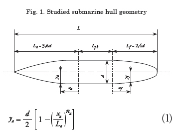
The submarine hull may be considered a body of revolution with some appendages, namely, a sail and stern rudders and planes. The radius of the body of revolution is given analytically for the aft and forward zones and in between there is a cylindrical or parallel middle body. Jackson (1992) proposed a parametric definition of the hull profile, which is shown in Fig. 1. The ship’s length is denoted L, the hull diameter d, and the parallel middle body length is Lpb. The aft zone has a length of La and its radius is given by ya. In the forward zone, the corresponding variables are Lf and yf.
xa is the aft longitudinal coordinate, being a value between 0 and La; for the forward zone, the coordinate is xf (between 0 and Lf); exponents na and nf are positive numbers that define the geometry shown in Fig. 1.
Submarine kinematics and maneuverability
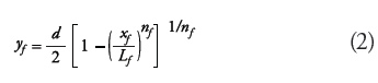
To model a submarine motion, all six degrees of freedom are significant. Consequently, in translational motion, the surge (x), sway (y), and heave (z) components must be considered, while for rotational motion the roll (around x), pitch (around y), and yaw (around z) components are considered. As usual, two coordinate systems are defined, an inertial one (or fixed on earth x0-y0-z0) and a moving one (or fixed on body x-y-z), the latter being aligned with the hull symmetry axis and the waterplane, having as a basis the NED convention (North/bow-East/port-Down) for the x-y-z directions, following Fossen (2011), and setting x = 0 at the midship. Fig. 2 shows the fixed and moving reference systems and the sign conventions for translational and rotational coordinates and velocities.
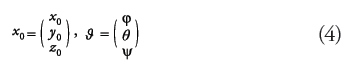
The unknown variables in this six-degrees-offreedom model are the linear velocity of point, O vo, and rotational (or angular) velocity of the body, ω. These two vectors are defined, thus:
where u, v, and w are the surge, sway, and heave velocities, respectively; p, q, and r are the angular velocities of roll, pitch, and yaw, respectively. The position with respect to the fixed coordinate system is denoted x0 and the submarine attitude is given according to the turning system, ZYX, and stored in vector ϑ, having three Euler angles necessary to define it.
Kinetics of the problem
The problem arises as a rigid body kinetics problem in which the submarine is a body subjected to a group of external forces and a three-dimensional motion is produced by their action. The set of forces mentioned comprises these sources: forces on the hull, FH , propulsion, FP , forces on the sail and control surfaces (rudder), FA , that is,
![]()
Hull forces include hydrodynamic forces, FHD , hydrostatic forces, FHS (buoyancy), and the ship’s weight, W.
![]()
The final equations of rigid body motion are those given by Fossen (2011) as Eqs. (3.41), having yg = 0 (for symmetry).
Evaluation of forces acting in a maneuver
Hull Forces
Within the hydrodynamic forces (FHD) some terms associated with the surge added mass exist; those found by the slender-body theory and those given by the viscous effect (axial resistance and cross-flow drag). The slender-body theory forces (FHD,slender) are derived from the integration of the material derivative of the added mass momentum:
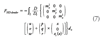
The material derivative in this model only considers the convective effect caused by the surge component:
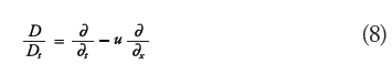
A necessary assumption is that the submarine moves at a depth greater than five times the diameter of its hull, as mentioned by Allmendinger (1990) and, hence, the effect of the surface and wave interactions can be neglected. The rotational degrees of freedom can be treated similarly so that a final formulation for slender-body theory moments is obtained. The algebraic expansion and the differential and integral treatment of the above definition yields:
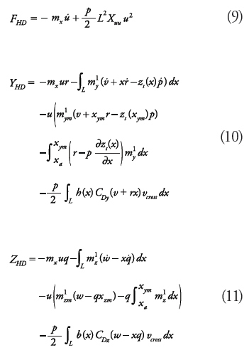
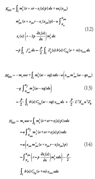
Xuu stands for a hydrodynamic coefficient associated with hull resistance (see section below). The crossflow drag coefficients (CDy, CDz) are assumed equal to 0.61, according to the averages reported by Bohlmann (1991). Functions h(x) and b(x) denote local height and beam of the hull; zs(x) is the z-coordinate of the center of mass of the sectional added mass; zp(x) is the z-coordinate of the center of pressure of the cross-flow drag; the local crossflow velocity is given by
![]()
Functions m'y , m'z and J'xx are the sectional added masses for sway, heave, and roll motion (added moment of inertia). For elliptic sections, the sectional added mass and moment of inertia are given by Sorotkin (2009):
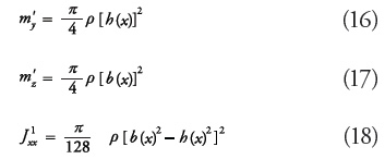
Note that for circular sections m'y = m'z, and J'xx= 0. Other zones of the vessel, whose cross-section is a circle with one or more ribs attached to it, have a different formula for their added mass and J'xx≠ 0 (see Sorotkin, 2009). Longitudinal positions xym and xzm are the locations of the maximum sectional added mass in sway (m'ym) and heave (m'zm), respectively. These values appear due to the flow separation premise of the slender-body formulation presented by Bertram (2000). The added mass in x, used in this work, is estimated as mx = 0,1m, according to Fossen (2011).
Propulsion force
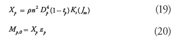
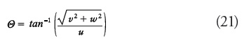
Regarding the thrust caused by the propulsion system, some data from the propeller (including its diameter DP) and the flow incidence angle, Θ , are needed. The longitudinal force due to propulsion, Xp, and the pitch moment produced by it, Mp, (here this moment is null as zP = 0).
Flow incidence angle is defined as:
Propeller speed (rev. per second) is given by:
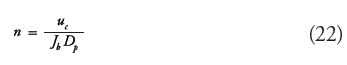
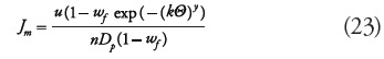
Jb is a constant parameter that acts as an initial advance coefficient set to determine n as a function of Dp and a desired speed, uc, which in this case is equal to the approach speed. An adjusted advance coefficient is proposed by Bettle et al., (2009) which is computed as follows:
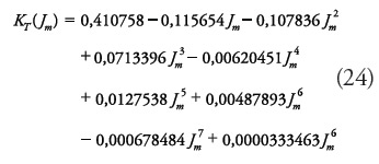
Hence, the thrust coefficient, KT , can be computed with a formula corresponding to a submarine modeled by Watt (2007), that is:
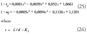
The formulae for thrust deduction and wake fraction are extracted by regression from Jackson (1992) for DP/d = 0.5
Forces on appendages
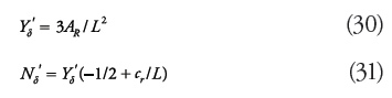
The rudder produces the following surge force, sway force, and yaw moment:
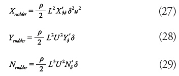
X'δδ is considered equal to 0.0208151, assuming the same condition studied in Mackay (2003). According to Spyrou (2003), the hydrodynamic coefficient associated to the rudder angle is computed as follows:
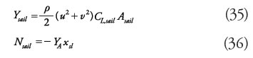
Another main appendage is the sail, whose resistance is analyzed as stated below, besides its trimming moment:
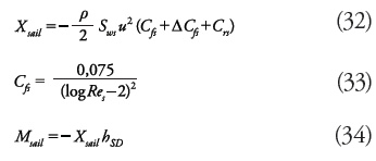
where CfS is the coefficient of friction of the sail, ΔCfS is the roughness coefficient, CrS is the residual resistance coefficient, ReS is the Reynolds number associated with the sail, and hSD is the z-coordinate of the sail’s drag center of pressure. Regarding the lift effect on the sail, the sway force and yaw moment produced is:
CL,sail is the lift coefficient of the sail and it is computed through the following expression by Whicker & Fehlner (1958):
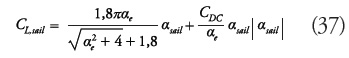
where the sail attack angle is:
![]()
Sail area is Asail = Lslhsl and αe and CDC are parameters specified below.
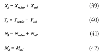
Summing up the terms above, the appendages’ contribution to the forces is:
Resistance model
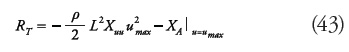
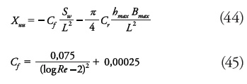
Hull resistance is evaluated by means of a formulation related to Reynolds number, Re, the wetted surface, Sw, and other geometric parameters (Bmax and L), according to ITTC (1978). Hull resistance plus the contribution from the appendages yield the total resistance of the submarine. This resistance is evaluated at the maximum speed, umax.
Hydrodynamic coefficient, Xuu, is defined as follows (Bohlmann, 1991):
Optimization Problem Definition
Design variables
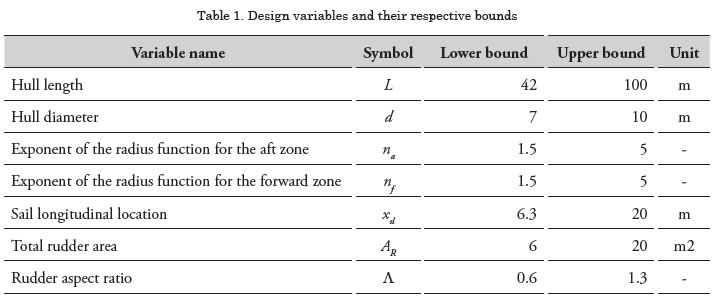
According to the parametric shape of the hull introduced above, the variables to set for the optimal design are described in Table 1, including the bounds of the valid interval for each variable. Some design variables are shown in Fig. 3.
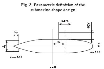
Rudder dimensions lr and cr (in Fig. 3), and design variables AR and Λ, are related by the following expressions:
![]()
Objective functions
The goal of the optimization proposed herein was to find design options from which the best performance can be attained by taking into account different criteria. In this case, the functions of the submarine operation are maneuverability and hydrodynamic resistance so that the problem may be stated thus:
• MINIMIZE Non-dimensional steady turning diameter: D’st (computed through simulation of a turning circle)
• MINIMIZE Resistance at the maximum speed, RT
In order to perform the turning circle simulation, the maneuverability model explained above is implemented and a rudder angle is applied so that the maneuver’s resulting velocities and position may be estimated and, thus, the turning diameter.
Resistance is evaluated at the maximum speed, which matches the approach speed of the turning circle, and the vessel is considered to be in pure surge.
Constraints
• Jackson (1992) implied that the parallel middle body length is greater than or equals zero, which in terms of L and d is:
![]()
• The location of the sail is usually between 15% and 20% of the submarine length, stated by Zalek & Tascon (2004):
![]()
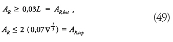
• Zalek & Tascon (2004) limit the rudder area to be at least equal to a proportion of
the product, Ld, (3% as for surface ships the
recommended proportion is 2%), and at the
most as a function of the envelope volume, ![]()
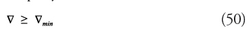
• The volume has to overtake a minimal capacity, ![]() :
:
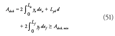
• The deck area must be greater than or at least equal to a given value Adeck,min :
• The rudder has to satisfy a geometric constraint of not spanning beyond the hull diameter, as proposed by Zalek & Tascon (2004):
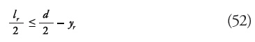
where
![]()
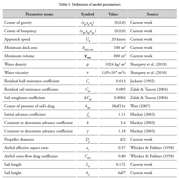
Parameters
The parameters of the model are set as indicated in Table 2. These were defined by decision of the authors in some cases, but these have been mainly justified with the definitions given in several references, which are specified in Table 2. Seawater physical properties in the table correspond to a temperature of 20 °C and salinity of 35 g/kg. Most of these parameters are constant and a few are a factor of d or L. The only varying parameter used is the rudder angle, δ , which varies between 20 and 30°.
Implementation and Results
Multiobjective optimization
In order to obtain a set of non-dominated designs (Pareto front), a genetic algorithm included in ModelCenter® software was used. The problem specifications consist of a population size of 100 and a maximum of 100 generations, with a stopping criterion of 8 generations without improving. Other parameters of the genetic algorithm are automatically fixed by ModelCenter®. Objective functions are implemented in MATLAB® files, which are called by the optimization tool. Both objectives are scaled. This is to guarantee handling an equal order of magnitude in both criteria. A [0,1] range was mapped from a resistance range of [100000N, 200000N] and from a nondimensional turning diameter of [0.7,1.4].
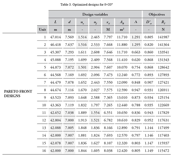
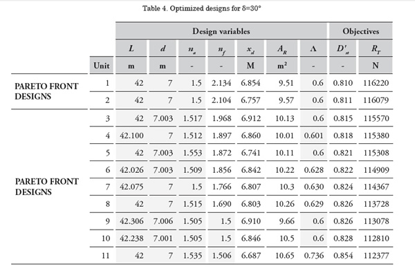
As stated above, two rudder angles were implemented. The case of 20° stopped after 65 generations and gave 16 designs while the 30° case ran all 100 generations with a final number of 11 designs. Top designs collected in the last generation of each case are specified in Table 3 and Table 4. In these tables, the shaded cells indicate the cases where the value of the variable was on or close to one of its bounds.
What is remarkable in Tables 3 and 4 is that variables L, d, and na tend to be close to their lower bounds for both rudder angles, while exponent nf approaches its lower bound a few times. The other variable reaching its bounds is the rudder aspect ratio, Λ, which achieves its upper limit in the minimal diameter solutions for δ = 20°, but being close to the lower one in almost all the designs for δ = 30°.
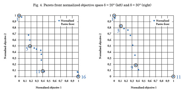
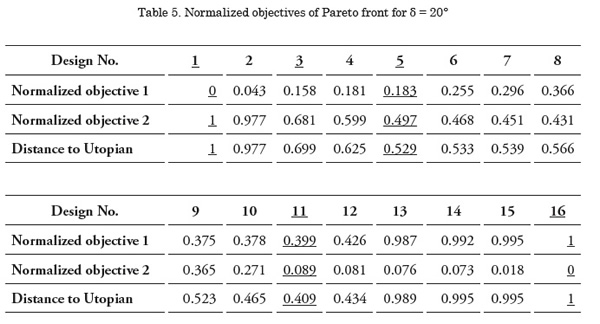
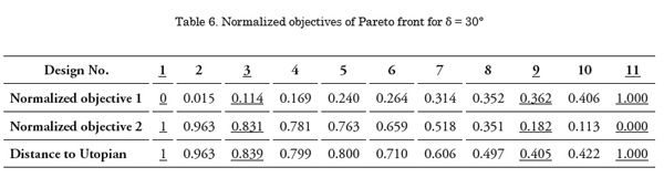
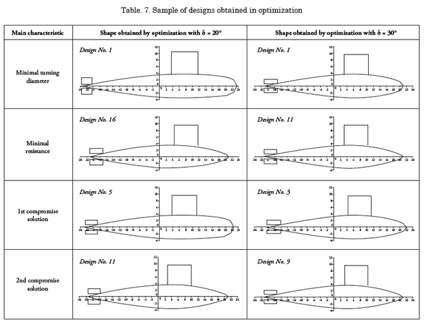
Though all of the designs belong to a Pareto front, the choice of one of these designs has to be made. One feasible criterion for decision-making is the evaluation of the proximity to the Utopian point. Nonetheless, more designs can be viewed as they appear to be well located in the front because they are located close to the minimal value in one objective and have a significantly better value in the other objective than that of the extreme case. In Fig. 4, the resulting optimal designs are plotted onto the objective space after being normalized to a [0,1] scale according with their maxima and minima. Objective 1 stands for the diameter and Objective 2 denotes the resistance. The origin of coordinates on such plots is considered an estimate of the Utopian point and, thus, a distance from it to every design of the front can be computed. The distance of every Pareto point to its corresponding Utopian point is given in Tables and 6. The designs of interest in the decision-making process are underlined in those tables and circled on each plot of Fig. 7. The corresponding submarine shapes are displayed in Table 7, comprising the extreme cases of minimal resistance and minimal diameter along with two compromise solutions.
Discussion of Results
By looking at the geometries in Table 7, some features are graphically identified from the solutions obtained through the genetic algorithm. For a minimal turning diameter, a bulkier forward zone of the hull is seen. Besides, a very slim aft zone is noticed in all designs. On the other hand, if the resistance is the minimization objective, a slim forward body is obtained.
The former observation is associated with how the maneuverability model was formulated. The integrals that compose the hydrodynamic forces equations and were derived from the slender-body theory are mainly evaluated between the section of greatest added mass and the bow due to the assumption of validity of flow separation, suggested by Bertram (2000) even though other sources, like Toxopeus (2010), state that such an assumption may not be totally accurate. Then, as seen in Bohlmann (1990) or Hooft (1982), hydrodynamic derivatives can be extracted from those integrals and, thereby, the integral limits cause an important effect on the ship’s stability and maneuverability. Given that the aft body shape has a smaller effect on the maneuvering coefficients, the forward part of the hull is the one that changes the most to optimize the design under the specified criteria.
In most cases, the length and hull diameter were at or close to their lower bounds. Because these variables are almost constant for every solution obtained, and the aft zone is thin, the shape of the forward body affects the wetted surface and its volume. By recalling the formula for hull resistance, it is clear that a greater wetted surface area increases resistance, so it is noticeable that this result is consistent with the expected solution.
For the 20° rudder angle, it is remarkable that design No. 5 can play the role of a compromise solution, given that when compared to both extreme cases this shows an intermediate geometry, while design No. 11 looks more like the minimal resistance design than that with the minimal turning diameter.
Regarding the second rudder angle, extreme cases are more alike than in the previous case, yet a more compromise-like choice can be seen in design No. 3, rather than in design No. 9 that is closer to the solution with optimized resistance. Nonetheless, this assessment is performed only visually, but if the decision-maker prefers another criterion, other points in the Pareto front might be chosen as the optimal design.
Concerning the constraint action, Tables 8 and 9 contain the data of the closeness to each constraint for the top designs obtained after optimization. The shaded cells show the cases where the constraint was active and the value was exactly on the limit or marginally (even fairly out of the boundary). It is observed that mainly all values are away from the limits, except for the length of the parallel middle length, which is zero or very small. While in the solutions where the turning diameter is closer to a minimal value the volume is not near the minimal required capacity, the volume constraint turns active when the chosen design is more focused on minimal resistance.
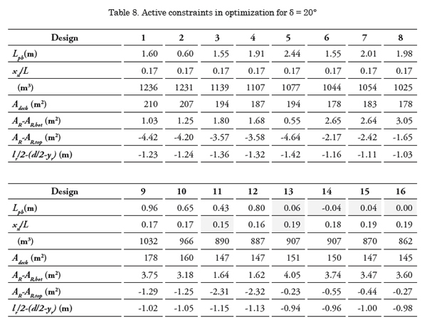
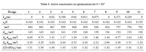
Design considerations presented by Allmendinger (1990) include some alternatives to reduce the drag of the submarine, which consist in increasing the length, reducing the wetted surface, or increasing the length-todiameter ratio. Regarding the first statement, although the length in all designs was about its lower bound, in one of the cases (rudder angle of 20°) it is seen that greater lengths are achieved for minimal turning diameter rather than for minimal resistance and, thence, the first alternative cannot be proven here. Nevertheless, resistance is minimized with a decreasing wetted surface (because this value is strongly related, see variation of the displacement in Tables 8 and 9) and, therefore, the second alternative proposed is verified, which agrees with the comment made above. A likely explanation to this is that the wetted surface (which is highly affected by the length) has a bigger influence on the ship’s resistance and the optimization process first tends to get to solutions with a more reduced length and later it makes wetted surface decrease by modifying the exponents of the shape functions. Thus, the third statement is proven as the highest length-hull ratio is attained only with the smallest hull diameter because the length has already been set about its lower bound.
Allmendinger (1990) also mentions that a desirable geometry for low drag is a long tapered hull form. This is easily checked on the designs obtained, where the aft body is very slim so that a tapered form is found.
Conclusions
A mathematical model for submarine motion was stated and implemented for parametrically defined hull shapes. Such a model may be used to simulate maneuvers in a virtual environment, as well as a design tool by means of an optimization technique that allows evaluating the best performance for a specified set of criteria.
Upon identifying two objectives, several design constraints were included to define a feasible space over which an optimization technique could be applied.
The resulting geometries showed consistency regarding the relationship between the hulls’ wetted surface and resistance. Furthermore, as expected, the minimal required capacity is fairly obtained in the designs of minimal resistance and is widely accomplished in the solutions with the smallest turning diameters.
The way optimization enhances the turning ability lies on the variation of the forward zone of the submarine’s hull because this part of the body affects the hydrodynamic derivatives the most and, therefore, the vessel’s maneuverability.
Some design considerations were observed to check if the resulting optimized solutions agreed with them. Due to this, a possible explanation was provided on how the optimization process led to the final set of designs.
There was a graphical identification of a compromise solution for both rudder angles considered in the optimization, but the data provided can be used by the decision-maker if a new criterion is preferred. As a prospective future work topic, implementation of a more complete model and other maneuvers is sought so that more reliable resulting designs can be obtained. That model could enhance the way appendages and propulsion forces are assessed, though the number of variables may increase if a higher complexity of the parametric geometry is present.
A deeper treatment of the slender-body theorem equations employed in this model is another purpose to be pursued. Taking into account interactions between the rudder and the hull and other effects not considered so far, a set of formulae for the hydrodynamic coefficients can be achieved, as done by Bohlmann (1990). With those coefficients explicitly computed, an analysis of stability can be performed, which can be incorporated to the optimization model as a new criterion or constraint.
References
ALLMENDINGER, E. E. 1990. Submersible Vehicle Systems Design. SNAME.
BERTRAM, V. 2000. Practical Ship Hydrodynamics. Oxford.
BETTLE, M. C.; GERBER, A. G; WATT, G.D. 2009. Unsteady analysis of the six DOF motion of a buoyantly rising submarine. Computers & Fluids 38.
BOHLMANN, H. J. 1991. An analytical method for the prediction of submarine maneuverability. RINA Warship ’91 Symposium on Naval Submarines 3, London.
BOHLMANN, H. J. 1990. Berechnung hydrodynamischer Koeffizienten von Ubooten zur Vorhersage des Bewegungsverhaltens. Dissertation. Institut für Schiffbau, Universität Hamburg.
CLARKE, D., GEDLING, P., & HINE, G. 1982. The Application of Manoeuvring Criteria in Hull Using Linear Theory. London, UK: The Royal Institution of Naval Architects.
FOSSEN, T. I. 2.011. Handbook of Marine Craft Hydrodynamics and Motion Control. Chichester, U.K.: John Wiley & Sons.
GABLER, U. 2000. Submarine Design. Bernard & Graefe Verlag, Bonn.
HOOFT, J. P. 1982. Advanced dynamics of marine structures. Wiley.
INOUE, S., HIRANO, M., & KIJIMA, K. 1981. Hydrodynamic Derivatives on Ship Manoeuvring. International Shipbuilding Progress , 28 (321), 112-125.
ITTC – Recommended Procedures. Performance prediction method, 1978, revised in 1987. Edited by the 22nd ITTC QS Group 1999.
ITTC. 2005. Final report and recommendations to the 24th ITTC, The manoeuvring committee. Proceedings of the 24th ITTC , I , 137-198. Edinburgh, U.K.
ACKSON, H. A. 1992. Fundamentals of Submarine Concept Design. SNAME Transactions 100, pp. 419-448.
KOROTKIN A. I. 2009. Added masses of ship structures. Springer Science.
MACKAY, M. 2003. The standard submarine model: a survey of static hydrodynamic experiments and semi-empirical predictions. Technical Report DRDC Atlantic TR 2003- 079.
NEWMAN, J. N. 1977. Marine Hydrodynamics. The M.I.T. Press.
SHARQAWY, M. H.; LIENHARD, J. H.; ZUBAIR, S. M. 2010. Thermo-physical Properties of Seawater: A Review of Existing Correlations and Data, Desalination and Water Treatment.
SPYROU, K. 2003. Ship manoeuvrability, Lectures Notes. Glasgow: Glasgow University.
TOXOPEUS, S. 2010. Validation of slender-body method for prediction of linear manoeuvring coefficients using experiments and and viscousflow calculations. Proceedings of the 9th International Conference on Hydrodynamics (ICHD 2010). China Ocean Press.
WAGNER-SMITT, L. 1971. Steering and Maneuvering of Ships – Full Scale and Model Tests. European Shipbuilding, Vol. 19, No. 6, and Vol. 20, No.1.
WATT, G. 2007. Modeling and simulating unsteady six degrees-of-freedom submarine rising maneuvers. Technical Report DRDC Atlantic TR 2007-0089.
WHICKER, L. F.; FEHLNER, L. F. 1958. Freestream characteristics of a family of lowaspect- ratio. All-movable control surfaces for application to ship design. David Taylor Model Basin, Report 933.
ZALEK, S.; TASCON, O. 2004. ME555-Design Optimization - Term Project: Submarine Hull Optimization. University of Michigan