Stability of Ships with a Single Stranding Point
Estabilidad de embarcaciones con varamiento de punto único
Paula C. de Sousa Bastos1
Marta C. Tapia Reyes2
Abstract
During rescue operations of stranded vessels, it is essential to make immediate and reliable decisions to optimize the successful salvage potential and minimize risks of environmental damages and cost impacts. Pursuant to this scenario, the need arises for a numerical tool, which can more accurately forecast the stability conditions experienced by a vessel after running aground and help in the refloating operations of the unit. This study seeks to develop an adequate calculus systematization, which provides analytical capabilities for operational situations in case of stranding, thereby, supporting the decisionmaking process in these risk situations.
Key words: stranding, single point, stability, algorithm, refloatin
Resumen
Durante operaciones de rescate de embarcaciones varadas, es esencial tomar decisiones inmediatas y confiables para optimizar el potencial de salvamento exitoso y minimizar el riesgo de daños ambientales e impacto de costos. De acuerdo con este escenario, surge la necesidad para una herramienta numérica, que pueda predecir de manera más precisa las condiciones de estabilidad que esté experimentando la embarcación luego de encallar y ayudar en las operaciones de reflotación de la unidad. Este estudio busca desarrollar una adecuada sistematización de cálculo, que brinde capacidades analíticas para situaciones operativas en caso de encallar, así, apoyar el proceso de toma de decisiones durante estas situaciones de riesgo.
Palabras claves: varamiento, punto único, estabilidad, algoritmo, reflotación
Date Received: October 15th, 2012 - Fecha de recepción: 15 de Octubre de 2012
Date Accepted: January 28th, 2013 - Fecha de aceptación: 28 de Enero de 2013
________________________
1Technical School, Federal University of Rio de Janeiro. Guayaquil, Ecuador. e-mail: paulabastos@poli.ufrj.br
2 Technical School, Federal University of Rio de Janeiro. Rio de Janeiro, Brasil. e-mail: martatapia@poli.ufrj.br
............................................................................................................................................................
Introduction
Damage sustained by vessels generates numerous losses, those caused by maritime accidents to ships or their cargo, as well as the costs to repair these damages, which include the vessel’s integrity and the environmental context. With the aim to minimize these expenses, it is mandatory to ensure agility and dependability of the decisions made during risk situations, such as the vessel's stranding, a quick check of compliance with requirements for stability and the maximum allowed effort for a given loading condition.
To achieve that, numerical tools should be used, which are capable of accurately forecasting the impact of the action plan to be followed. Even if the operational expertise enables rescuing the vessel, it is important to have a duly validated support tool in place.
Within this context, this paper seeks to develop a calculus algorithm that enables outputting replies about a vessel's stability in case it runs aground, taking into account the circumstances endured by the vessel, which acts as an aid to decisionmaking and maximizes the reliability of refloating operations. The vessel's integrity is, thus, ensured along with environmental conservation.
Stranding
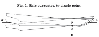
A stranded ship does not respond in the same way as when it is floating freely. Part of its weight is supported by the seabed, and the ground produces a reaction force. Under these different conditions, the static stability behavior undergoes changes, making the ship more vulnerable to damage
This paper develops a study about the theoretical analysis of static stability in a stranded ship resting on a single support point.
In a stranded ship resting on a single support point, the reaction is applied on point 'P' and the ship may rotate around the three coordinate axes passing through this point. When this happens, there are displacement variations and, if the weight remains unchanged, the reaction force will also vary. However, the weight added or removed from the vertical axis going through the support point does not cause rotation because it does not cause moment; therefore, it does not cause any variations in displacement. In this case, the variation in reaction force equals the variation in weight. When it is possible to take the draft measurements while the ship is stranded, both buoyancy and its center may be calculated by integrating the submerged part of the hull. The center of gravity may be defined by the load conditions. The reaction point may be determined by the balanced weight, displacement, and moment of the reaction force.
After stranding, the position of the center of gravity does not change. However, under static balance conditions, a partially floating (stranded) ship behaves like a ship from which a weight had been removed, equaling the ground reaction at a given position. That is why the virtual change in the center of gravity is considered.
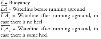
Where:
G = Position of the center of gravity before stranding
Gv = Virtual elevation of the center of gravity
P = Application point for the reaction force
x = Distance between the center of gravity, G, and the midship section
xv = Distance between the application point for the reaction force and the midship section
Q = Tide height necessary to refloat the ship
Modeling the Stranding Event
Seldom are the conditions prevailing during a stranding completely identifiable, which makes rescuing a ship a critical procedure.
Some methods exist to refloat grounded ships, but none is absolutely exact due to the different circumstances to which the vessel may be subjected, given that no circumstance is absolutely predictable by numerical simulations.
In the case of stranding events, one should consider the ship’s characteristics, loading conditions, the ship’s fore and aft drafts, balance and stability, conditions, height of the waterline, type of ground, and tide range in the location where the incident took place.
This analysis will enable establishing the reaction force and the position where the latter is applied to the ship. As soon as this information is obtained, one may check the vessel’s stability by calculating the height of the center of gravity and the metacentric height.
The effects of tide range and weight movement onboard the ship on stability will also be examined, as well as the ship refloating process.
All appraisals will be verified through a stranding simulation to validate the study.
Reaction force (R)
The value of the reaction force (R) is obtained by the difference between the ship’s displacement before and after the stranding has taken place, and can be calculated after determining the fore and aft drafts in a single point, without any damage to the bottom compartments. After reading the value of these drafts, it is possible to establish the equivalent draft. Obtaining the equivalent draft for a vessel that has run aground with a maximum degree of accuracy entails some complexity because the ship may be in a state that includes some heel and/or trim. However, it is important to establish this parameter because it is necessary to calculate the ground reaction force, which is applied to the grounded ship.
The method suggested in the U.S. Navy Salvage Manual – Volume 1 – Strandings and Harbor Clearance [1] has been employed to calculate the equivalent draft (Eq. 1), where the draft is established by the fore, midship, and aft draft measurements on both sides. The average between the average port and starboard drafts indicates the draft known as Tm1.
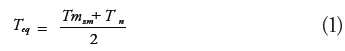
Where:
Tmn= average of midship drafts taken on the port and starboard sides
Tm2= average of Tm1 and Tmn drafts
This equivalent draft value is very close to the actual value. The error between the calculated value and the actual value may be due to the ship’s hogging or sagging.
Position of the Reaction Force
The coordinates of the point where the reaction force is applied may be calculated based on displacement and the state of the ship after having run aground. The virtual movement of the vessel’s center of gravity is also taken into account.
Longitudinal position of the reaction force (LCR)
In order to establish the longitudinal position where the reaction force (LCR) is applied, one employs:
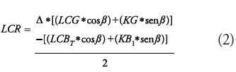
Where:
Δ = Ship's displacement before running aground [ton]
LCG = Longitudinal position of the center of gravity before running aground [m]
β = Trim angle [°]
KG = Vertical position of the center of gravity before running aground [m]
LCB= Longitudinal center of buoyancy [m]
LCBT = LCB position after running aground corrected for trim [m]
KB1 = Vertical position of the center of buoyancy after running aground [m]
The KB1 values are obtained by the hydrostatic curves corresponding to the equivalent draft after running aground.
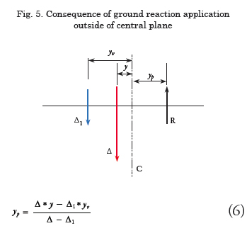
Transversal position of the reaction force (TCR)
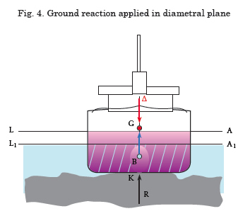
The effect of the ground reaction away from the diametral plane is equivalent to a virtual movement of the center of gravity transversally equal to yv.
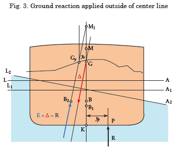
M = Metacenter height before running aground
M1= Metacenter height variation after running aground
G = Position of the center of gravity before running aground
Gv= Virtual elevation of the center of gravity
B = Position of the center of buoyancy before running aground
B1= Position of the center of buoyancy after running aground, in case there is no heel
B2= Position of the center of buoyancy after running aground, in case there is some heel
P = Application point of the reaction force
yv= Distance between the virtual position of
the center of gravity, Gv, and the center line
yp= Distance between the application point of the reaction force and the center line. If the force of the application takes place along the central plane, yp equals zero.
Δ = Ship's displacement before running aground
R = Reaction force
Applying the reaction force to a different point along the center line causes a heel condition. The heel angle may be measured by the draft marks on port (TBB) and starboard (TBE), which correspond to the longitudinal center of flotation (LCF).
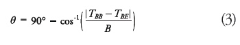
In order to establish the transversal position where the reaction force is applied, one employs:
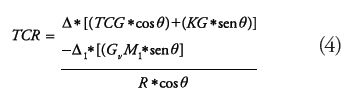
Where:
TCG = Transversal position of the center of gravity before running aground [m]
θ = Heel angle [°]
KG = Vertical position of the center of gravity before running aground [m]
Δ1= Ship's displacement after running aground [ton]
GvM1 = Virtual variation in the metacentric height after running aground [m]
Vertical position of the reaction force (VCR)
The reaction force is applied onto the ship's bottom. Taking the baseline as reference, the vertical position where the reaction force (VCR) is applied equals zero.
Stability
If a ship is stranded on a point, it can tilt freely in one or both directions, and may run into danger. A wide tide range may cause changes in the ground reaction, which may compound the stability issue.
To perform the stability analysis, it is necessary to establish:
• The effective or virtual increase in the center of gravity height (KG/VCG)
• The variation in metacentric height (GM) after the ship has run aground
Center of gravity height (KG1)
Changes to the position of the center of gravity are virtual changes; the center of gravity does not shift given that the weight remains unchanged. However, the ship behaves as if this position had shifted. There are two options to calculate with the reaction force applied either to the central plane or outside this central plane.
Reaction force applied to central plane
If the reaction force is applied to the central plane, the vertical position of the center of gravity may be established by the summation of static moments in relation to K.
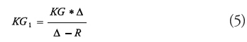
Reaction force applied outside the central plane
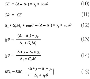
In this case, the calculation of the center of gravity height depends on the heel angle. When the ship's heel is high (> 8°), the approximation to GZ cannot be taken into consideration; therefore, one considers two possibilities for low heel and high heel values.
Low Heel
If the reaction force is not applied to the central plane, the ship's heel will depend on the heeling moment. Considering a case where the ship's heel is low (8°), the starboard distances are positive and the port distances are negative, the resulting moment equals the sum of the component moments.
If a stable ship remains balanced while heeling, a righting moment attempts to return it to the balanced position without heel. In the case of stable ships with usual shapes, the metacenter position for angles up to 8° may be considered constant. Under these circumstances, one may consider the righting arm, GZ, as being:
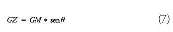
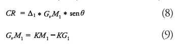
The restoration moment for any inclination angle represents the vessel’s ability to recover its original position. This value is calculated when the vessel is on quiet waters and momentarily at rest, i.e., acceleration forces due to motion may be dismissed. Thus, the recovery conjoint (CR) is obtained by:
For the ship to retain its heel angle there must be a moment equal to the module and which is opposite of the recovery conjoint. This other conjoint is called heeling conjoint (CE).
High heel
When the ship’s heel angle is above 8°, the approximation to GZ is no longer valid because the metacenter does not have a 'fixed position'; the variation of the submerged shape is higher, so that the metacenter also varies according to the transversal inclination angle.
When a ship tilts, the center of buoyancy (B) moves constantly and its transversal position depends on the heel angle and on the ship's displacement.
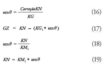
GZ depends, foremost, on the ship's KG. Because G may take up numerous positions, it is convenient to consider the value of GZ, which would exist if G were on the keel (KN) and then correct it to G's actual height.
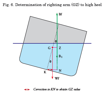
Therefore,
![]()
The heel angle and KM1 are known. The latter is drawn from the hydrostatic table for displacement after the ship's stranding.
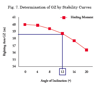
The stability curve, which represents the heeling moment, is drawn and it is obtained by the following equation:
![]()
The intersection of the curve with the heel angle with which the ship partially floats defines the vessel's GZ under these circumstances. If GZ is known, one may be able to establish KG1.
Virtual variation in the metacentric height (GvM1)
After having run aground, the ship has a new waterline, which is different from the former (prior to stranding).
The KM1 value may be determined by the hydrostatic curve through the actual draft after stranding. The new metacentric height may be determined by:
![]()
Effect of changing weights onboard
Weight control is widely used to reduce ground reaction in stranding situations. One should always pay attention to the effects of this procedure on stability and balance, for if the position of the vessel's center of gravity is not controlled; the ship may become unstable or be brought into danger when it is refloated.
The most evident effect when shifting weights onboard a ship is the variation in the ship's center of gravity and displacement, which may cause changes to the bottom shapes, involving shifts in the vertical and longitudinal position of the center of buoyancy, possible changes in the transversal position of the center of buoyancy, and changes in the longitudinal and transversal metacentric radii. Therefore, there will be changes in the transversal and longitudinal metacentric heights. Shifting weights in the ship may cause variations in the heel and in the drafts and, as a result, there will be changes to the vessel's trim.
Variation in the ship's center of gravity
Variation in the ship's longitudinal center of gravity (LCG2). Variation in the LCG will occur according to the variation in the center of gravity of the weight removed.
Where:
LCG1 = Position of the ship's longitudinal center of gravity before weight removal [m]
w = Weight removed [ton]
lcg = Longitudinal position of the center of gravity of the weight removed [m]
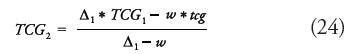
Variation in the ship's transversal center of gravity (TCG2). Variation in the ship's transversal center of gravity due to variations in weight, calculated for the weight moment, is determined by:
Where:
TCG1= Position of the ship's transversal center of gravity before weight removal [m]
tcg = Transversal position of the center of gravity of the weight removed [m]
Variation in the ship's vertical center of gravity (VCG2). Variation in the ship's vertical center of gravity (KG) due to variations in weight, calculated for the weight moment, is determined by:
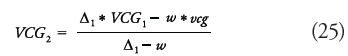
Where:
VCG1= Position of the ship's vertical center of gravity before weight removal [m]
vcg = Vertical position of the center of gravity of the weight removed [m]

Regarding the removal of liquid cargo, if the compartment is partially filled, one should consider the effect of free surfaces in these tanks. The virtual change to the center of gravity due to the effect of free surfaces is expressed by:
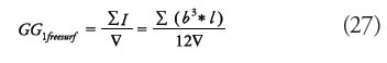
Where:
![]() = Volume displaced by the ship, taking into account the weight that has been removed [m³]
= Volume displaced by the ship, taking into account the weight that has been removed [m³]
The effective KG value will be:
![]()
Therefore, the effective metacentric height will be:
![]()
The KM2 value is obtained through hydrostatic curves for the ship's new displacement corresponding to this state of removed weight.
Changes in trim
If the weight reduction onboard changes the ship's center of gravity, the center of buoyancy ceases to be in the same vertical line as the center of gravity. Hence, the vessel will display variations in trim, thus, displacing the center of buoyancy until the two occupy the same vertical line. This change in weight, w, introduces a trim moment. To quantify the resulting trim arising from the shift in the center of gravity one employs:
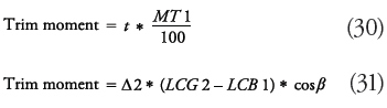
Where:
LCB1 = Longitudinal center of buoyancy before weight removal [m]Δ2 = Vessel's displacement after weight removal [ton]
For small trim angles, one may consider cos β as being equal to 1. Therefore:
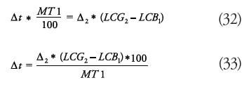
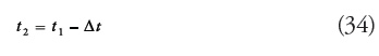
To establish the trim associated with the ship’s new state, one simply subtracts the value found for trim variation from the initial trim value:
Heel changes
Removing weight onboard may cause changes to the heel angle. The resulting transversal tilt may be deduced from the static stability curve.
In this case, as long as the stranded values for the center of gravity height and displacement are known, in an analogous fashion to the procedure described on the item on high heel values, a curve is drawn against the static stability curve, which corresponds to the heeling moment. The intersection between these two curves reveals the new heel angle in which the vessel may be floating freely or partially.
Fore and aft drafts
Changes to fore and aft drafts after the weight onboard has been shifted may be obtained by the ratio between buoyancy variation and the changes to the midship draft.
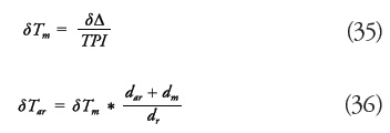
Where:
δΔ = Displacement variation [ton]
δTm = Midship draft variation [m]
δTar = Aft draft variation [m]
δTav = Fore draft variation [m]
dav = Distance between LCF and PR [m]
dr = Distance between LCF and the reaction center [m]
dar = Distance between the reaction center and
PV [m]
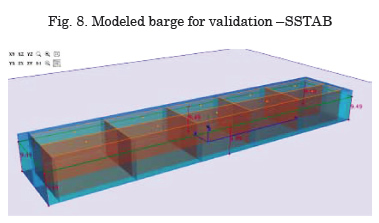
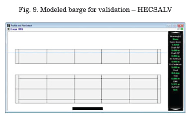
Validation of the Proposed Model
To validate the proposed formulation, a barge has been modeled on the SSTAB and Hecsalv software applications, with the following characteristics:
• Length: 120 m
• Breadth: 24 m
• Depth: 12 m
• Total loading capacity: 20,930.40 ton
• Total ballast capacity: 10,184.40 ton
The adopted coordinate system complies with the following conventions:
• X: midship origin (fore, positive; aft, negative).
• Y: center line origin (port, positive; starboard, negative).
• Z: baseline origin (up, positive; down, negative).
Stranding Simulations
The loading conditions chosen for the simulation of the hypothetical stranding situations refl ect a total loading capacity in which all cargo tanks are totally fi lled with a product whose specifi c mass is 0.85 ton/m³. Under these conditions, the barge has a parallel draft of 9.49 m.
Three hypothetical stranding situations were set up on SSTAB, the fi rst through the application of an upward vertical force to simulate a stranding event causing trim; the second in which heel takes place; and the third in which concomitant longitudinal and transversal tilt takes place. The situations have the following characteristics:
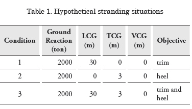
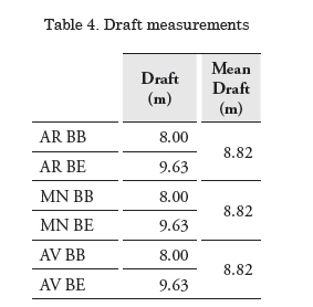
For each situation, SSTAB calculates the balance position, providing readings for six drafts in the following positions:
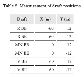
The procedure to validate the proposed formulation consists of inputting draft and heel angle values onto the HECSALV software, which should estimate the value of the stranding force with its corresponding application position. The results obtained will be compared with the values inputted onto SSTAB.
Stranding situation 1
This situation has the following values for draft and heel angle:
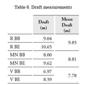
Tav = 7.78m
Tar = 9.84m
θ = 0°
These input parameters are inputted onto HECSALV, as outlined on Fig. 10.
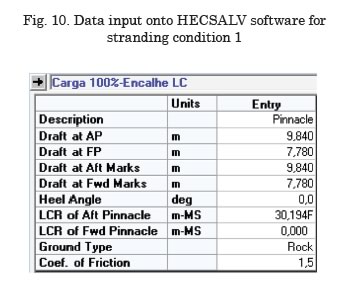
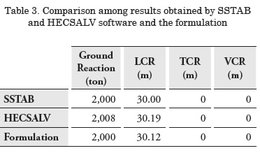
The following table shows a comparison between, on the one hand, the stranding force and the application position created by SSTAB and, on the other hand, the estimated values of the proposed formulation, as output by the HECSALV software.
A slight diff erence is noticed between the results obtained by the HECSALV and SSTAB software applications. Th is diff erence is due to the fact that HECSALV does not consider the virtual change in the center of gravity due to the application of the stranding force. In the proposed formulation, this consideration is made, bringing this result closer to the actual result.
Stranding situation 2
This situation has the following values for draft and heel angle:
θ = 3.876°
These input parameters are inputted onto HECSALV, as outlined on Fig. 11.
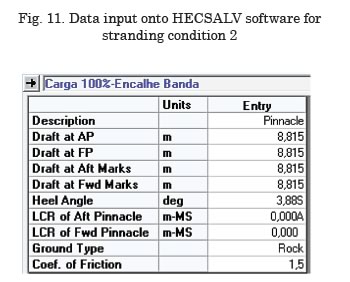
Table 5 shows a comparison between, on the one hand, the stranding force and the application position created by SSTAB and, on the other hand, the estimated values of the proposed formulation, as outputted by the HECSALV software.
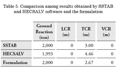
As mentioned, the HECSALV software does not consider the virtual rise in the center of gravity due to the stranding event. In this case, where the reaction force is applied outside the center line, it is possible to see that this lack of consideration produces a larger diff erence than in the case involving longitudinal tilt.
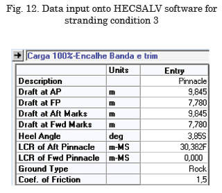
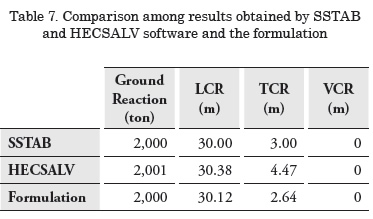
Stranding situation 3
This situation has the following values for draft and heel angle:
θ = 3.853
These input parameters are inputted onto HECSALV, as outlined on Figure 12.
The following table shows a comparison between, on the one hand, the stranding force and the application position created by SSTAB and, on the other hand, the estimated values of the proposed formulation, as outputted by the HECSALV software.
Weight shifting in the event of stranding
Upon considering the same model used in the stranding simulation, which included trim and heel, one will notice the unit's behavior on the SSTAB software after shifting the cargo and a comparison should be possible with the results obtained by the proposed formulation of the present study. Th e stranding situation is as follows:
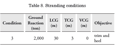
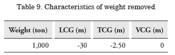
In the situation faced by the stranded ship, some weight aboard will be removed, which has the following characteristics:
The formulation developed herein and the SSTAB simulated modeling produced the following results:
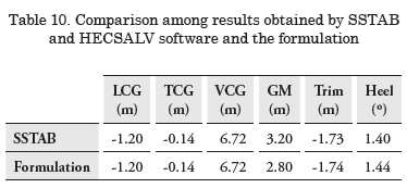
It is possible to see that the values are very close together, and the largest difference found pertains to the value of GM. That is due to the fact that the software does not consider the change in the center of gravity due to the reaction force. It was, therefore, found that the formulation is consistent, given that we observed a lower result, when taking this factor into account.
Conclusion and final considerations
This paper sought to create a calculation algorithm to reliably facilitate and optimize the salvage potential of a stranded vessel.
Re-flotation procedures for a ship that has run aground cannot be wholly predicted due to various conditions, which the vessel may be faced with on the occasion. However, for the cases analyzed here, the theoretical background developed in this study proved adequate. After carrying out the check tests, the results were satisfactory because there was only a slight difference between the results produced by the simulated model and the formulation after the necessary considerations were made.
As a follow-up to the work carried out, it would be interesting to devise a future study about the portrayals of a stranding event on a rigid plane and on a viscous plane, given that the behavior displayed by the ship in these cases would be different to the conditions proposed by the present study. For these kinds of occurrences, one should take into account the limits of the stranding plane and some physical factors of the soil where the unit has grounded.
After considering these static stranding cases, it would also be convenient to carry out a dynamic analysis of a grounded ship, taking into consideration the effects of waves and currents. It would, thus, be possible to represent the occasion closest to the real scenario, providing more accuracy and safety to the ship's refloating operation.
References
U.S. Navy Salvage Manual - Volume 1 - Strandings And Harbor Clearance - Published by Direction of Commander, Naval Sea Systems Command.
Mecânica do Navio, Estática – Parte V - Equilíbrio De Corpos Parcialmente Flutuantes.
Ship Structure Committee 2003 - Predicting Motion and Structural Loads in Stranded Ships, Phase 1.
HECSALV Salvage / Emergency Response Software – Developed and Supported by Herbert Software Solutions, Inc.
SSTAB Software – Desenvolvido por CENPES / Petrobras e Grupo de Tecnologia em Computação Gráfica (TeCGraf) / PUC-Rio de Janeiro.