Analysis of most frequent cases of vibration in propulsion systems
Análisis de casos más frecuentes de vibraciones en sistemas de propulsión
Franklin Jhonny Domínguez Ruíz1
Abstract
This study is a review of cases of propulsion systems in which noise, vibration, or fracture problems have existed. Case studies are presented on passenger vessels, tugboats, tankers, and ferry boats. Each case is addressed based on lateral, torsional, axial vibration analysis, as well as the case analysis of the possible coupling of frequencies or possible defect or deterioration of a component. Based on the cases, a summary is presented of inertial masses of each system analyzed to establish possible problems and benchmark statistical considerations when selecting the components of a propulsion system. Calculations were performed using the ShaftDesigner software from Machine Support, Holland and Torcal software from Tecnavin S. A.
Key words: vibration, torsional, lateral, noise, fracture, propulsion
Resumen
El presente estudio constituye una revisión de casos de Sistemas de Propulsión, en los que se han presentado problemas de ruido, vibraciones, fracturas. Los casos de estudio son presentados en naves de pasajeros, remolcadores, tanqueros, lanchas ferry. El abordaje de cada caso se presenta basado en el análisis de vibraciones, laterales, torsionales, axiales, según sea el caso, análisis del posible acoplamiento de frecuencias o posible defecto o deterioro de algún componente o defecto de construcción. En base a los casos presentados, se presenta un resumen de masas inerciales de cada sistema analizado, para establecer, estadística referencial de problemas y posibles consideraciones al momento de seleccionar los componentes de un Sistema de Propulsión. Los cálculos son realizados usando el software ShaftDesigner de Machine Support, Holanda y Torcal de Tecnavin S. A.
Palabras claves: vibración, torsional, lateral, ruido, fractura, propulsión
Date Received: October 20th, 2012 - Fecha de recepción: 20 de Octubre de 2012
Date Accepted: April 2nd, 2013 - Fecha de aceptación: 2 de Abril de 2013
________________________
1Tecnavin S.A. Guayaquil, Ecuador. e-mail: navser@gye.satnet.net
............................................................................................................................................................
Introduction
Frequently, noise and vibration problems occur in propulsion systems. Because of this, this study presents analyses of cases of problems that have been solved, as well as the example of a propulsion system without any type of inconvenience.
At the end, we present a statistical analysis of the percentage of principal inertial masses that participate in each model to have as reference when defining a propulsion system.
This study does not seek to become a publication with formulations; rather, it seeks to share experience developed in propulsion systems.
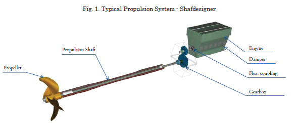
General components of a propulsion system
The main components of a propulsion system to be considered in this analysis are as as shown in Fig. 1.
Lateral vibrations in the propulsion system
Lateral vibrations in a propulsion line can be caused by: the gyroscopic effect of the propeller, thrust imbalance, inadequate distance between supports or lack of rigidity in bedplates and/or buttresses.
When these vibrations occur in a propulsion system, they can cause fracture, failure in system components or on the ship’s structure, producing:
• Complete destruction of the propulsion
system;
• Reduction of the service life of shafts and/or their components;
• Fatigue fracture on support brackets and/or engine mountings;
• Increased seal wear and damage;
• Excessive noise, vibrations on the hull and superstructure.
The natural frequency of lateral vibrations and critical frequencies of the system were calculated through the Finite Elements method, considering the following terms of reference:
• The bocin support center close to the propeller,
taken from a distance of one shaft diameter,
measured from the aft end of the bocin
support, close to the propeller;
• The center of support for the other bearings
was taken at the center of the length of the
bocin support;
• The propeller inertial mass was calculated
through integration of radial sections;
• The propeller added mass was estimated using
the methodology proposed by Parsons M.G. et
al., (1980) and with the aid of the PRAMAD
software.
• Modeling of the line was considered up to
include the thrust bearing.
Torsional vibration in a propulsion line
Torsional vibrations in a propulsion system can be produced by any of these possible causes:
• Aging of the frontal damper,
• Misfiring of a cylinder,
• Inadequate flexible coupling,
• Excess diameter in the propulsion line, among
others.
The excitations most frequently used in torsional analysis are generated by the propeller and the internal combustion engine.
• For propeller excitations, the Classification
Societies recommend values in percentages of
propeller torque.
• For propeller engine excitations; normally,
this information is provided by engine
manufacturers. If this information is
missing, we may use the harmonic tangential
components provided by Lloyd’s Register.
Torsional vibrations occurring in a propulsion system can cause fracture, failure in system components, gear damage, premature destruction of flexible couplings.
Frequently, fractures in shafts or crankshafts, due to torsional effect, occur in 45° direction.
The methodology to model a propeller system for torsional analysis is based on the equation:
![]()
Where [I], [C], [K], [F (t)], are the inertial mass matrices, damping, stiffness, and excitation, respectively.
The natural frequencies of torsional vibrations and the responses of the forced analysis of the system were calculated through the matrix solution method, considering the following terms of reference:
• Include the frontal damper with its inertia,
stiffness, and relative damping;
• Include inertial mass and cylinder absolute
damper, crankshaft stiffness;
• Include the flexible coupling with its inertial
mass, stiffness, relative damping, and energy
dissipation limit;
• Include the gearbox with its inertial mass,
stiffness, diameters, stiffness of gear teeth.
Avoid synthesizing the gearbox branches;
• Propulsion shafts: Add as much inertial mass
as necessary in case of section changes.
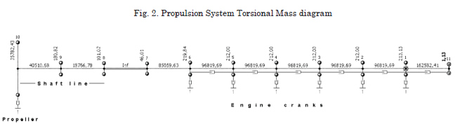
The precision of the calculations of system response will depend on the reliability of the input data, which is why it is recommended to request information on inertial mass, stiffness, and damping from the equipment manufacturers.
For the added mass and the propeller damping, the methodology proposed by Parsons M.G. et al., (1980) and the PRAMAD software were used.
Fig. 2 presents a model example of inertial mass without branches.
Vibration analysis in a propulsion line
The vibrations in a propulsion system can be caused by lateral, torsional, axial effect or by its possible frequency couplings.
Adequate configuration of elements of a propulsion system, separation of supports, stiffness of supports and/or struts must be conducted taking into consideration the recommendations of Classification Societies and the manufacturers of the system’s components.
In the cases shown ahead, frequencies were calculated in the three orientations: lateral, torsional, and axial, to after that verify the possible coupling of frequencies of the system with the structure.
The case studies analyzed in this study are as indicated:
1. Inadequate selection of the flexible coupling
on a tanker
2. Change of propeller on a tanker
3. Inadequate separation of supports on a
passenger ship
4. Alteration of the distance between supports on
a tugboat
5. Restriction in the operation range on a yacht
6. Inadequate stiffness in struts and inadequate
separation of supports
7. Inadequate selection of flexible coupling and
diameter of propeller shaft in fishing vessel
8. Example of a propulsion system without
vibration problems
Case study 1: Inadequate selection of flexible coupling on a tanker
Type: Tanker
Length: 103.35 m
Engine: 1300 KW MCR
RPM: 500
Propeller: CPP
This case was analyzed by request of re-engining. Frequency analysis was carried out for lateral and torsional vibrations.
Through analysis, it was found that the flexible coupling is sub-dimensioned, which is why we recommend:
• Changing the flexible coupling according to
the system’s needs;
• Operating the system in restricted manner until the flexible coupling mentioned can be
replaced.
• Diminish the power developed by the
controllable pitch propeller, under conditions
of misfiring.

Case study 2: Change propeller on a tanker
Type: Tanker
Length: 120.55 m
Engine: 2574 KW MCR
RPM: 200 - 620
Propeller: FPP
This case was analyzed by request of change of heavier propeller.
The original propeller presented cracks and section detachment in several blades.
Frequency analysis was carried out for lateral and torsional vibrations.
Analysis revealed that by maintaining the system’s original components, with the new propeller, the range of operation under conditions of misfiring of a cylinder would be restricted from 200 to 417 rpm.


Case study 3: Inadequate separation of supports on a passenger ship
Type: Passenger Ship
Length: 78.40 m
Engine: 782 KW MCR
RPM: 600 -1800
Propeller: FPP
This case was analyzed by request of re-engining and because vibrations are being noticed on the first support of the prop shaft from the gearbox. Frequency analysis was carried out for lateral and torsional vibrations.
Lateral analysis shows that the system’s natural frequencies and critical frequencies are within the working range.
Based on this analysis, the support structure for the first suport was inspected, finding that the structure was corroded.
It was recommended to relocate the supports to minimize the system’s frequencies from being within the working range.

Case study 4: Alteration of the distance between supports on a tugboat
Type: Tugboat
Length: 34.90 m
Engine: 1566 KW MCR
RPM: 600 – 1800
Propeller: FPP + Fixed Nozzle
This case was analyzed because of the presence of persistent noise in the propulsion system within the interval of 650 to 700 rpm. Vibration measurements were made with a triaxial accelerometer.
With these vibration readings, wear was detected on gears of the gearbox (excessive backlash).
Frequency analysis was made for lateral and torsional vibrations, taking into consideration the wear of the gear teeth and the possible relocation of the stuffing box support.
Through a sensitivity analysis, increased wear was found on the gear teeth, a possible relocation of this support in 300 mm would offer the possibility of resonance of the lateral frequency with the torsional frequency.
Lateral analysis shows that the system’s natural frequencies and critical frequencies are within the working range.
Based on this analysis, the support structure for the first break was revised, finding that the structure was corroded.
It was recommended to relocate the supports to minimize the system’s frequencies from being within the working range.

Repair recommendation
• Inspect the stuffing box and restore the bearing
to its original position.
• Inspect the structural condition of the nozzle.
• By relocating the stuffing box bearing, as
suggested, we expect to increase the system’s
lateral frequency from 1527 rpm (mode 1 order
1Z) to 1580 rpm (mode 2 order 2Z+1), expecting
slight vibration at speeds close to 1600 rpm.
Case study 5: Alteration of the distance between supports on a tugboat
Type: Yacht
Length: 35.40 m
Engine: 2 x 328 KW MCR
RPM: 600 – 1800
Propeller: FPP
This case was analyzed due to a propulsion counter shaft fracture.
Frequency analysis was conducted for lateral and torsional vibrations.
Inspecting the system, it was found that the countershaft presents abrupt section change, close to the gearbox flange, which causes stress concentration, increasing the of the countershaft fracture risk.
From vibration analysis, we found that within the range of operation close to 900 rpm, there is increased vibratory torque in the flexible coupling; thereby, we recommend restricting operations in this rpm range until changing the flexible coupling.

Case study 6: Lack of stiffness on struts and inadequate separation of supports
Type: Yacht
Length: 39.07 m
Engine: 2 x 255 KW MCR
RPM: 600 – 1800
Propeller: FPP
This case was analyzed because of noise and vibrations in the range of 850 to 950 rpm, in both bands.
Frequency analysis was performed for lateral and torsional vibrations. Frequencies were estimated on the struts by using the finite elements method.

From these analyses, it was concluded that due to the likelihood of frequency coupling:
• The structure of the struts is not sufficiently
stiff,
• Inadequate separation of supports.
Case study 7: Inadequate selection of flexible coupling and diameter of propeller shaft on fishing vessel:
Type: Fishing Vessel
Length: 19.21 m
Engine: 2 x 317 KW MCR
RPM: 450 – 1225
Propeller: FPP
This case was analyzed due to excessive vibrations on the vessel.
Frequency analysis was conducted for lateral and torsional vibrations.
From the analysis, it was concluded:
• The flexible coupling has excess stiffness
(original rubber blocks). We recommend
acquiring another less stiff coupling.
• The original propulsion shaft with a diameter
of 4 pl. SAE C1018 is producing frequencies
within the working range. We recommend
changing the propeller shaft for one with a
smaller diameter of 3.5 pl. of Aqualoy material.

Summary of Inertial Masses for Systems analyzed
To summarize the case studies presented, Table 3 includes the inertial mass of each equipment / component, to statistically relate the percentage of inertial masses that should be considered before definitely selecting equipment or components.

Acknowledgments
We express our gratitude to all the companies which have entrusted us with the solution to noise and vibration problems. Special thanks go to the personnel from:
• Tecnavin S. A. for developing the
TORCAL software, dedicated analysis of
torsional vibrations;
• Machine Support, Holland, for allowing
us to use the SHAFTDESIGNER software;• Vulkan, Germany, for the technical
support provided.
References
CATERPILLAR, “Performance Parameters, TM3310”, 2009.
DEN HARTOG J. P., “Mechanical Vibrations”, 1966.
NESTORIDES E. J., “A Handbook on Torsional Vibration”, B.I.C.E.R.A., 1958.
PARSONS M. G., VORUS W. S., RICHARD E., “Added Mass and Damping of Vibrating Propellers”, The University of Michigan, 1980.
PARSONS M. G., “NA 531, Marine Propulsion Plant Vibration”, Notes, The University of Michigan, 1981.
TECNAVIN S. A., “Manual de usuário de TORCAL V9-25”, 2012.
VULKAN, “Technical Data”, 2012.
WILSON KER, “Practical Solution of Torsional Vibration Problems”, 1948.