Assessment of appendage effect on forward resistance reduction
Evaluación de apéndices para disminución de la resistencia al avance
Marcos Salas1
Gonzalo Tampier2
Abstract
This paper shows experimental and numerical results of three types of appendages on forward resistance reduction of displacement and semidisplacement hulls. Forward resistance results were obtained by using Computational Fluid Dynamics and towing tank tests. The appendages evaluated are stern flaps and interceptors for displacement hulls and spray railspray rails for a semiplaning hull. The experiments are independent from each other and no research was undertaken to include the combined effect of appendages on a single hull. The predicted reduction in forward resistance in all three tested devices is around 5-10%, showing potential for fuel saving through the evaluation of hydrodynamic effects of energy saving appendages.
Key words: forward resistance, appendages, numerical tests, experimental tests, CFD, towing tank
Resumen
Este trabajo contiene resultados experimentales y numéricos del efecto de tres tipos de apéndices en la disminución de la resistencia al avance en cascos de desplazamiento y semidesplazamiento. Los resultados de resistencia al avance han sido obtenidos mediante Dinámica de Fluidos Computacional y experimentos de remolque en tanques de pruebas. Los apéndices evaluados son flap e interceptores de popa para cascos de desplazamiento y spray railspray rails para un casco de semiplaneo. Los casos estudiados son independientes entre sí y no se ha realizado un análisis que incluya el efecto combinado de ellos actuando conjuntamente en un casco. La reducción estimada de la resistencia al avance, en los tres apéndices experimentados, es alrededor de 5-10%, mostrando que existe potencial para ahorro de combustible por medio de la evaluación de los efectos hidrodinámicos de estos apéndices para ahorro de energía.
Palabras claves: resistencia al avance, apéndices, ensayos numéricos, ensayos experimentales, CFD, canal de pruebas
Date Received: January 12th, 2013 - Fecha de recepción: 12 de Enero 2013
Date Accepted: March 1st, 2013 - Fecha de aceptación: 1 de Marzo de 2013
________________________
1University Austral of Chile, Faculty of Engineering Sciences. Valdivia, Chile. e-mail: msalas@uach.cl
2University Austral of Chile, Faculty of Engineering Sciences. Valdivia, Chile. e-mail: gonzalo.tampier@uach.cl
............................................................................................................................................................
Introduction
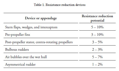
Due to constantly increasing fuel costs and the growing pressure to reduce pollutant emissions, it is increasingly important to consider every means to reduce fuel consumption. Even a small reduction in the required energy could mean economic survival in the long run. Savings of 1 to 5% in fuel expenses, considered non-relevant in the past, are now crucial to the economic performance of merchant ships and fishing vessels; moreover, even military vessels are under great pressure to reduce fuel consumption due to economic and environmental reasons. A number of devices are available to reduce forward resistance; their effectiveness is not well proven and usually there is little more than a sales approach to claim savings that are sometimes unreliable and based on results from a single ship under very particular conditions. To further complicate matters, is it very difficult to evaluate the effective performance of a hydrodynamic device in real operational conditions. In effect, the variation of sailing conditions, sea state, loading, hull fouling and many other variables make it almost impossible to compare the fuel consumption of a ship with and without a fuel savings device, especially when saving margins are as narrow as 1 to 10%. Some examples of devices currently in use and their potential for resistance reduction are shown in Table 1.
Due to the difficulties encountered in full-scale evaluation of fuel saving devices, it is crucial for scientific research to undertake such an evaluation.
This paper is focused on the performance evaluation in forward resistance reduction of stern appendages: flaps and interceptors, and spray railspray rails used to decrease the wet surface in planing and semiplaning hulls.
No attempt was spent on joint testing of combined devices, given that the hydrodynamic interaction of appendages is difficult to analyze and scale effects could provide confusing results. It should be warned that the potential to reduce resistance of devices, presented in Table 1, is not possible to be added directly, moreover, the combined effect of two or more of these appendages could result in a negative contribution, i.e., increasing total resistance.
Stern Flaps
A stern flap is an appendage built in form of a plate that extends aft of the transom at an angle relative to the ship’s buttock plane. Its interaction with the hull modifies the ship running trim, reduces propulsion resistance, and increases maximum attainable speed. The critical parameters for a stern flap geometry design are: chord length, flap angle referenced to an extension of the hull bottom, and flap span across the transom. Stern flaps have been investigated for displacement hulls, (Cusanelli et al., 1999), semidisplacement hulls, (Salas et al., 2004), and planing hulls. On small planing crafts, a stern flap affects the running trim angle by four to five degrees, (Millward, 1976). This variation is the principal reason of the reduction in resistance on these types of hulls.
In contrast to the planing hull case, a stern flap affects the trim angle by 0.1 to 0.3 degrees on vessel displacements. This amount of trim change does not produce significant resistance reductions. The principal powering benefits on these vessels are attributable to the induced change in the flow field around the propeller and reduced flow separation at the stern. The flow field change reduces the drag on the stern zone and modifies the ship’s wave resistance.
Assessment of Stern Flaps on a Displacement Hull
Stern flaps were evaluated on a displacement hull. Flap angles were chosen at 0, 5, and 10º; preliminary tests were also carried out for flaps with 15º, showing poor performance of this configuration. The chord length of the flaps was 1, 1.5 and 2% of LPP (DEFINE). Experimental tests of the displacement hull with stern flaps were carried out at in the towing tank at Universidad Austral in Chile. This tank is 45 m long, 3 m wide and 1.8 m deep. Details of the model, flaps tested, and the experimental setup can be found in (Jiménez, 2009). Computational Fluid Dynamics (CFD) was employed to obtain numerical simulations of resistance tests. The theoretical model is based on Navier-Stokes equations solved for an isothermal three dimensional flow of a viscous fluid with constant physical properties. No theoretical development of the method is given in this paper, as can be found in the technical literature, (Ferziger and Peric, 2002); (Bertram, 2011); (Baos, 2011).
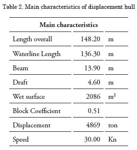
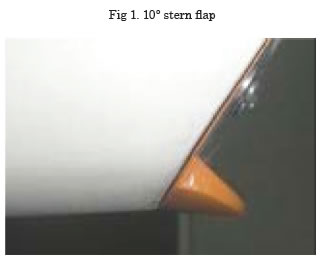
The hull’s main characteristics are shown in Table 2 and the stern flap mounting is shown in Fig. 1. Considering the towing tank dimensions and the maximum speed, a scale of λ = 80 was selected to build the model and flaps.
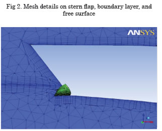
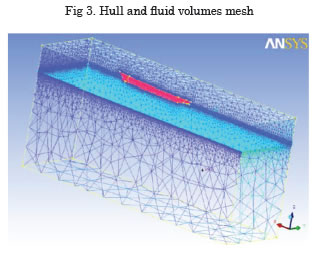
Numerical CFD simulations were carried out by using ANSYS CFX code. The meshing was allowed to be coarse in non-sensitive fluid regions far from the hull and refined in sensitive areas like the free surface, hull boundary layer, and stern flap. The stern flap and fluid mesh are shown in Fig. 2 and the virtual towing tank is shown in Fig. 3.
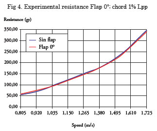
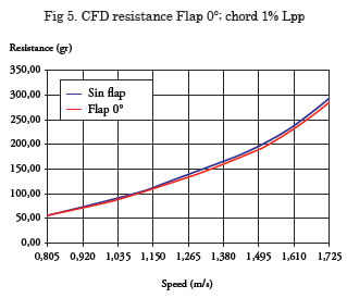
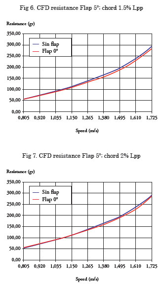
Selected experimental and CFD resistance results for model scale are shown in Figs. 4 to 7. It can be appreciated in Figs. 5 and 6 that modest, but consistent, benefits can be achieved with chord lengths 1% and 1.5% of LPP, respectively. Less efficient results can be observed in Fig. 7 for 2% chord length.
Interceptors
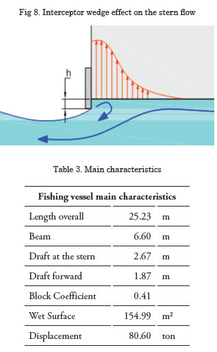
An interceptor is a device designed to intercept water flow under the hull. It is usually a simple flat plate that can be built in steel or any other material. It modifies the pressure field at the stern by creating a virtual wedge, as shown in Fig. 8. An interceptor is much simpler to install compared to a flap; its length under the hull can be adjusted, so it can be adjusted to perform optimally at any particular speed.
Interceptor performance on a Fishing Vessel
To achieve a reduction of ship resistance of a fishing boat, CFD simulations of interceptors were investigated for two interceptor lengths under the hull: 5 and 10 centimeters. Numerical results were compared to towing tank results available from tests performed at ETSIN towing tank in Madrid, Spain (see ETSIN 2002 and Sepúlveda 2006). The main characteristics of the fishing vessel are presented in Table 3.
The fishing vessel resistance tests were carried out for equivalent speeds of 10, 12, 14, and 16 knots.
The interceptors were mounted across the stern reaching a width of 4.208 m and depth under the hull of 5 and 10 centimeters in full scale.
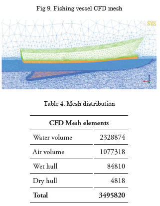
Taking advantage of symmetry, only half of the hull and virtual towing tank were modeled in the CFD simulations. The fluid domain was created according to the Iowa University recommendations to avoid modeling fluid regions not affected by the hull movement. Local mesh refinements were created to adequately model fluid flow in relevant fluid regions like the boundary layer, free surface, and interceptor vicinity, as shown in Fig. 9. The total amount of fluid cells created was about 3.5 million, as detailed in Table 4.
Interceptors results
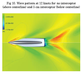
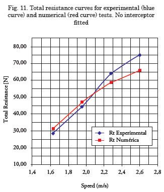
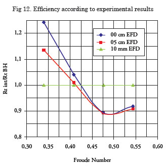
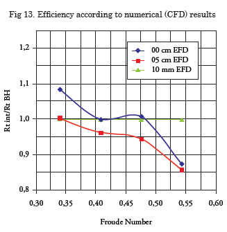
CFD simulations were able to predict the interceptor effect on smoothing stern wave patterns at all speeds, as an example the wave pattern behind the stern at 12 knots is shown in Fig. 10. Regarding total resistance, there is some discrepancy with the towing tank results in the predicted resistance of the hull, no interceptor fitted, for higher speeds, as presented in Fig. 11; however, the predicted trend is similar in both approaches, both predicting significant benefit in the resistance reduction at higher speed, given interceptor effects, as noted in the experimental and CFD results shown in Figs. 12 and 13.
Interceptor efficiency
Both, towing tank and CFD, results predict a significant reduction of resistance at higher speeds, despite differences in the reduction shape, as seen in Figs. 12 and 13, there is agreement in the resistance reduction potential of about 10% at higher speeds for the 5 cm interceptor. The 10 cm interceptor was predicted to be slightly less efficient.
Spray railSpray Rails
The Spray railSpray rails main function of spray rails is to separate the spray that characteristically builds-up at the bow of planing and semiplaning crafts. The purpose is to reduce the associated resistance and improve operational conditions, given that sometimes the spray becomes so large that it comes over the deck and may affect visibility. Spray railSpray rails are usually avoided by incorporating discontinuities into the hull shape; hard chines also serve that purpose. Sometimes these geometric discontinuities are insufficient to detach the spray from the hull; in these cases, a spray rail can be pre-designed or retrofitted without major difficulty.
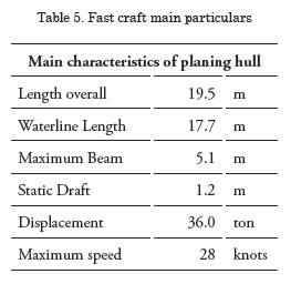
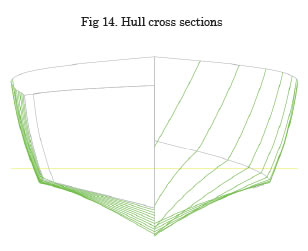
Spray railSpray rails were numerically simulated to evaluate their effect on the dynamic wet hull and the forward resistance. The hull chosen was a hard chine planing hull with maximum speed of 28 knots. The hull’s main characteristics are presented in Table 5 and cross sections are shown in Fig. 14.
Spray rail results
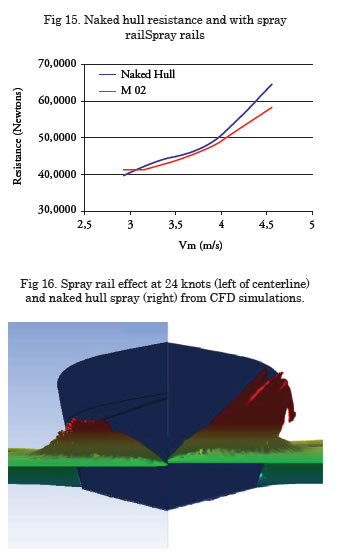
As expected, at lower speeds the effect of the spray rail is negative because the added wet surface increases frictional resistance. This adverse effect is not really a problem for these types of boats, which very seldom operate at low speeds. As speed increases, the spray rail pays off and there is noticeable resistance reduction (Fig. 15), which improves at high speeds. Undoubtedly, this positive outcome is the result of the spray being detached from the hull at the bow, as appreciated in Fig. 16, where spray railspray rails effects are displayed for 24 knots.
It must be warned, however, that the beneficial influence of the spray rail is not guaranteed. Initial simulations with other spray rail locations and shapes proved useful to detach the spray from the bow, but very disappointing in their resistance performance, (Díaz, 2012).
Conclusions
It has been shown that simple appendages like stern flaps, interceptors, and spray rails can produce hydrodynamic effects resulting in reduced forward resistance. For stern flaps and interceptors, the gains arise from the change of the pressure field at the stern; for the spray rail, the reason is evidently the significant reduction of the dynamic wet surface.
Towing tank and CFD results showed good agreement in predicting the potential benefits of the appendages tested; however, some quantitative discrepancy is present in the estimated total resistance, especially at higher speeds.
CFD was proven useful in estimating forward resistance and it was also possible to visualize wave patterns for the stern flaps and interceptor cases, moreover, the spray from the semiplaning hull was also well simulated.
The predicted reduction in forward resistance in all three devices tested is around 5-10%, this is a major potential for fuel saving and in itself merits a careful evaluation of hydrodynamic effects of energy-saving appendages in any prototype being designed.
The scope for improvement is open for large displacement hulls as for small planing hulls, however, due care has to be exercised in selecting the right size and positioning of a hydrodynamic appendage because the wrong size or inconvenient location could result in actually increasing resistance and powering.
A cautious analysis should be performed on the combined use of energy-saving devices; the total result is by no means the addition of each device acting independently. It should be expected that several devices operating simultaneously will surely be interdependent and the total result could be, at the very least, lower than the addition of individual contributions, or plainly detrimental to the overall resistance performance.
Acknowledgements
The stern flap research was sponsored by the Chilean Navy; the author is grateful for the technical and financial support. Several Naval Architecture students from Universidad Austral in Chile collaborated at different stages of the research presented in this paper, namely: Patricio Jimenez, Miguel Ahumada, César del Rio, Jorge Díaz, and Rodrigo Baos were all involved either in the experimental tests or CFD simulations.
References
BAOS, RODRIGO (2011). “Diseño de Interceptores para Embarcaciones de Pesca Mediante Códigos CFD”. Universidad Austral de Chile 2011.
BERTRAM, VOLKER (2011). “Practical Ship Hydrodynamics”. Butterworth-Heinemann. Second Edition.
CUSANELLI, D., KARAFIATH, G., AND LIN, CHENG WEN (1999). “Stern Wedges and Stern Flaps for Improved Powering Performance – U.S. Navy Experience”, SNAME Annual Meeting, Sept. 29 – Oct 2, 1999, Baltimore, M.D.
DÍAZ, JORGE (2012). “Comparación Numérica de Dispositivos de Reducción de Resistencia al Avance en una Embarcación de Semi-Desplazamiento”. Universidad Austral de Chile, 2009.
ETSIN (2002). “Estudio de optimización hidrodinámicas de las formas de una serie de buques pesqueros de casco de PRFV” . Proyecto N° 0104. Canal de Ensayos Hidrodinámicos E.T.S.I.N., UPM, 02 de abril 2002.
FERZIGER, J. H.AND PERIC, M. (2002). “Computational Methods for Fluid Dynamics.” 3rd edition, Springer, 2002.
JIMÉNEZ, PATRICIO (2009). "Análisis experimental de una serie de flaps de popa en unidad de desplazamiento". Universidad Austral de Chile, 2009.
MILLWARD, A. (1976). “Effect of Wedges on the Performance Characteristics of Two Planing Hulls”, Journal of Ship Research, Vol. 20, No. 4, Dec. 1976.
MULLER-GRAF, BURKHARD (1991). The effect of an advanced spray rail system on resistance and development of spray of semi-displacement round bilge hulls. FAST 91. First International Conference on Fast Sea Transportation, Trondheim, Norway, June 1991.
SALAS, M.; ROSAS, J. AND LUCO, R. (2004). “Hydrodynamic Analysis of the Performance of Stern Flaps in a Semi-Displacement Hull”. Latin American Applied Research. Vol. 34.
SEPÚLVEDA, PATRICIO (2006). “Diseño de interceptores en pesqueros utilizando pruebas experimentales y códigos CFD”, E.T.S.I.N., Abril 2006.