T = thrust
DP = propeller diameter
va = inflow velocity
ρ = water density
Application-optimised propulsion systems for energy-efficient operation
Sistemas de propulsión de aplicación optimizada para operación energéticamente eficiente
Stefan Kaul1
Paul Mertes2
Lutz Müller3
Abstract
Today, optimal propellers are designed by using advanced numerical methods. Major revolutionary improvements cannot be expected. More essential are the design conditions and the optimal adaptation of the propulsion system according to the operational requirements. The selection and optimisation of the propulsion system based on a systematic analysis of the ship’s requirements and the operation profile are the prerequisites for reliable and energy-efficient propulsion. Solutions are presented, which accommodate these issues with a focus on steerable rudderpropellers. Considerations include the efficiency potential of the propulsor itself, optimisation of the engine propeller interaction, and optimisation of a demandresponsive energy supply. The propeller-thruster interaction is complex, but offers some potential for optimisation. Results of examinations show this. The power distribution between multiple propellers at high loads of limited propeller diameters increases the efficiency. This can be done by double-propeller systems like the SCHOTTEL TwinPropeller or by distributing the power on several thrusters. This distributed propulsion offers economic operation and an increased lifetime by means of the demandresponsive use of energy. An efficiency-optimized electric motor instead of the upper gear box reduces the mechanical losses in the case of diesel-electric propulsion. An example: the SCHOTTEL CombiDrive.
Key words: propulsion, efficiency, azimuth steering, cavitation, load distribution.
Resumen
En la actualidad, las hélices óptimas son diseñadas mediante el uso de métodos numéricos avanzados. No se pueden esperar grandes mejoras revolucionarias. Más esenciales son las condiciones de diseño y la adaptación óptima del sistema de propulsión de acuerdo a los requerimientos operacionales. La selección y optimización del sistema de propulsión basado en un análisis sistémico de los requerimientos del buque y el perfil de operación son los prerrequisitos para propulsión confiable y energéticamente eficiente. Se presentan soluciones, que acomodan estos asuntos con un enfoque sobre hélices de timón dirigibles (steerable rudderpropellers). Las consideraciones incluyen el potencial de eficiencia del propulsor en sí, la optimización de la interacción entre la hélice y el motor y la optimización de un suministro de energía que responda a la demanda. La interacción de hélice y el propulsor es compleja, pero ofrece algún potencial para optimización; los resultados de las pruebas lo demuestran. La distribución de potencia entre múltiples hélices con altas cargas de diámetros de hélice limitados aumenta la eficiencia. Esto se puede lograr por sistemas de doble hélice como el Doble Hélice de SCHOTTEL o mediante la distribución de potencia en varios propulsores. Esta propulsión distribuida ofrece operación económica y ampliación de vida útil mediante el uso de energía que responda a la demanda. Un motor eléctrico de eficiencia óptima, en vez de la caja de engranajes superior reduce las pérdidas mecánicas en el caso de propulsión diesel-eléctrica. Un ejemplo: El SCHOTTEL CombiDrive.
Palabras claves: propulsión, eficiencia, gobierno azimutal, cavitación, distribución de la carga.
Date Received: October 22th, 2010 - Fecha de recepción: 22 de Octubre de 2010
Date Accepted: January 27th, 2011 - Fecha de aceptación: 27 de Enero de 2011
________________________
1SCHOTTEL GmbH, Spay/Rhine, Germany. e-mail: skaul@schottel.de
2SCHOTTEL GmbH, Spay/Rhine, Germany. e-mail: pmertes@schottel.de
3SCHOTTEL GmbH, Spay/Rhine, Germany. e-mail: lmueller@schottel.de
............................................................................................................................................................
Introduction
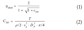
Ideal propeller efficiency is derived from the ratio of thrust-to-propeller power, which gives the following relationship as a function of the thrust load coefficient CTH.
T = thrust
DP = propeller diameter
va = inflow velocity
ρ = water density
These equations clearly show that increasing thrust load coefficient correlates with decreasing potential efficiency of the propeller. This is the case if the thrust requirement is high and/or the propeller diameter is small and/or the inflow velocity is low.
This is basic information and nothing new. It clearly shows, however, that the choice of development parameters significantly influences efficiency.
Fig. 1 shows the efficiency curve of propulsion systems as a function of the thrust load coefficient.
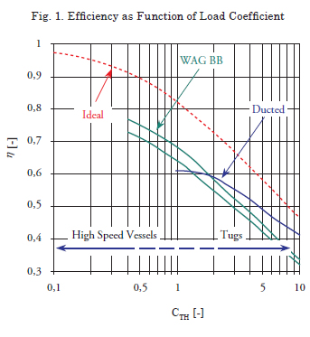
Three approaches are indicated below:
1. Improvement of efficiency by means of doublepropeller
systems, e.g. STP.
2. Use of multiple-propulsion systems on a vessel.
3. Dosed, load-dependent power distribution,
e.g. double-ended ferries.
These measures to increase the efficiency result in further challenges for development engineers, such as calculation of the steering forces, optimisation of the housing with regard to cavitation properties, and interaction of the hull and propeller. Due to the increased power density of the propulsion systems combined with the restricted space for installation and the demands for higher velocities, it is precisely these issues that necessitate great numerical and experimental effort in the development work during design and optimisation.
Propulsion Technology: STP, SCD, Thruster Interaction
STP technology - Interest in improved-efficiency Rudderpropellers began to grow during the early 1990s. The particular reason for this was increasing thrust load and the demand for greater power input in relation to the propeller cross-section, which generally goes hand in hand with efficiency losses.
With multi-propeller systems, on the other hand, in which power is distributed between two or more propellers, it is possible to significantly reduce this disadvantage. Solutions with two contrarotating propellers have been known for a long time. However, this technology entails a complex mechanical design with twin gear trains and a shaft running within a hollow shaft, involving an elaborate sealing arrangement.
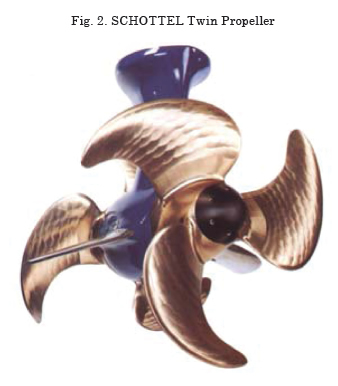
For this reason, SCHOTTEL looked for a simpler solution and developed the principle of the STP based on an analogy with pump and turbine technology. The propellers are mounted here on a single shaft and, thus, rotate in the same direction; in addition, a guide system is installed between the propellers.
Essentially, two principles are implemented here:
• The distribution of the power between two
propellers instead of a single heavily loaded
propeller.
• The re-use of the swirl energy generated by the
front propeller, which would otherwise be lost.
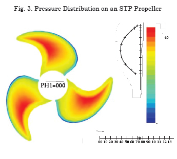
If a propeller with a limited cross-section must transmit a large amount of power, this presents the designer with a difficult task. The pressure distribution on the blade must satisfy certain criteria. At the blade edges and especially at the tips, it is necessary to reduce the load to avoid losses due to flow around the blade edges. One possibility is to increase the number of blades, although beyond a certain point this increases the grid induction losses, as the losses due to blade interaction are known. It is also necessary to avoid high-pressure gradients in the distribution, otherwise cavitation may result.
The distribution of power between two propellers permits a much more homogeneous distribution of the pressure and ultimately significantly improved blade geometry with greater efficiency. As a result of the load distribution, global cavittion is no longer a critical factor.
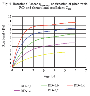
Depending on the thrust load and the designrelated pitch, the propeller outflow contains tangential velocity components, which do not contribute to thrust generation and which are generally termed rotational or swirl losses. Fig. 4 shows the proportion of swirl energy as a function of the thrust load coefficient and the pitch.
The guide system between the propellers consists of guide fins and the vertical stem of the underwater housing. This interposed guide system deflects the tangential components in the outflow from the front propeller and redirects them in an axial direction. The lift effect on these guide components gives rise to forces, which reduce the housing resistance and boost forward thrust. As already mentioned, the mechanical components, especially the underwater gear train with its bearing arrangement, require a housing of a certain size. Of particular importance here is the symbiosis of hydrodynamic contour and mechanical expedience.
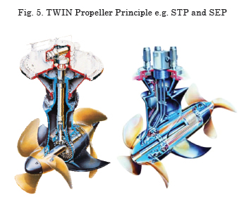
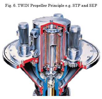
In general, the mechanical design of the STP does not differ fundamentally from that of the SRP. The propeller shaft extends out of the underwater housing on both sides, allowing a propeller to be mounted at each end. A second shaft seal and two additional exchangeable fins are required. The twin-propeller principle is also implemented in the so-called pod drives. Pod drives have an electric motor integrated in the underwater pod; the propellers are directly mounted on and, thus, driven by the drive shaft of this motor. Both modes of operation are illustrated in Fig. 5.
Hence, STP is an integrated total solution, which takes account of all the relevant hydrodynamic aspects.
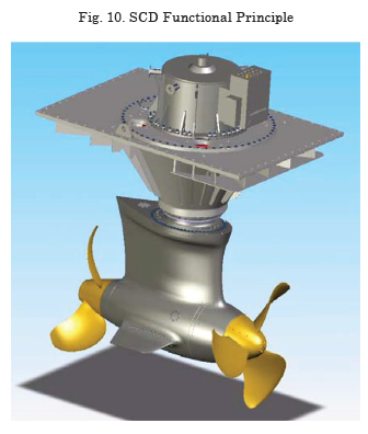
SCD - The SCD (Fig. 6) is a new form of propulsion system. Instead of an above-water gearbox, it has an electric motor compactly integrated into the support cone of the Z-drive that drives the vertical shaft. In the underwater gearbox, speed is stepped down to the propeller speed in the conventional manner by using a bevel gear stage. This design is highly space saving and combines the advantages of an electric propulsion system with the serviceproven reliability of a mechanical Z-drive. The gear losses are reduced by about half due to the absence of an above-water stage.
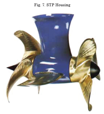
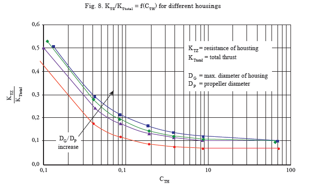
Influence of housing in Z-drives - One extremely important aspect is the design of the underwater gearbox housing. The fineness coefficient of the housing and the ratio of the pod diameter to the propeller diameter have a decisive influence on the overall efficiency of the system. In the design as push propeller, the housing disturbs the propeller inflow. Steering the system results in greater irregularity of the inflow, particularly for larger steering angles. This goes hand in hand with the increase in load fluctuations that are transferred via the outer shell and the point of integration into the vessel and have a negative effect on the noise level. This design has the advantage, however, that the housing is not located in the accelerated propeller outflow and can be better counter-balanced, which generally results in significantly reduced steering forces. In the design as pull propeller, the propeller inflow is disturbed less. The housing is located in the accelerated propeller outflow, resulting, on the one hand, in increased housing resistance. On the other hand, the pod and stem act like a rudder with a Costa propulsion bulb. The goal here is to create housings with very low resistance, but which also achieve a high degree of de-swirling. Consequently, a pod shape was chosen for the STP, which not only provides the maximum diameter at the requisite point, but which also has a remarkably low resistance coefficient (Fig. 7).
Systematic investigations show the importance of good housing design.
Systems that are not heavily loaded require as slender a housing as possible and a good propellerto- housing diameter ratio. Fig. 8 shows model test results with four different housing forms. The resistance KTZ of the underwater housing of the rudderpropeller is plotted as ratio of the total unit thrust, KTtotal, as a function of the thrust load coefficient, CTH. Further influential factors are the propeller pitch and the propeller advance ratio.
Application-adapted Thrusters
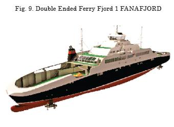
The following example is intended to illustrate the possibilities and significance of applicationspecific selection and design of the propulsion system. SCHOTTEL GmbH fitted five doubleended ferries of the Norwegian shipping company FJORD 1 with four steerable Z-type drives each. The ferries are of identical design; the only difference is in the size of their propulsion systems. The three ferries with the larger propulsion systems can reach speeds of 22 knots, while the two ferries with the smaller propulsion systems achieve speeds of 18 knots. The ferries have been in operation on coastal and fjord routes in southern Norway since the end of 2006.
The propulsion systems in question are gaselectric- driven with high demands on availability, redundancy, and stopping, acceleration and manoeuvring characteristics, particularly in highly confined cruising areas. For this reason, a comfortable power reserve was planned into the four propulsion systems fitted.
Principal dimensions and propulsion units:
LOA = 129.80 m
LPP = 122.40 m
LWL = 128.87 m
BOA = 18.70 m
TMax = 4.10 m
Disp. = 3899 t
Thruster SCD 2020
PInput = 2750 kW
nInput = 800 min-1
i = 3.154:1
DP = 2650 mm
ηMech = 0.975
Thruster STP 1515
PInput= 1800 kW
n Input = 1000 min-1
i = 4.470:1
DP = 2400 mm
ηMech = 0.950
Problem description - It is no exaggeration to describe the operation of the ferries as “extreme”. Speeds in excess of 20 knots (here 21 – 24 knots) remain the exception with conventional, mechanical Z-drives and require special measures in terms of design and housing geometry. Furthermore, the ferries and the propulsion systems are subjected to massive deceleration on every crossing to keep idle times as short as possible. This is achieved by reversing the Z-drives at full speed before entering the harbour; thereby, reducing the speed of the vessel to approximately 10 knots. The loads generated correspond to a crash stop manoeuvre, with the difference that this is not a one-off or rare emergency occurrence, but a frequently recurring standard manoeuvre.
The highly narrow design of the vessels with extremely V-shaped frames generally requires the use of a head box. Major design effort is required to achieve a configuration that generates as little resistance as possible. CFD provides a good means of implementing an effective draft process. The vessel shape described still results in a large distance between the hull and the housing, leading to a large lever arm. The mechanical structure has to meet these high demands, while the design has to improve the housing geometry with a view to flow separation, housing resistance and cavitation.
The two measures necessary here, in the fields of mechanical engineering and fluid dynamics, mutually hinder one another:
• The propeller torque that can be transferred
determines the necessary diameter of the forcetransferring
crown wheel in the underwater
gearbox. This defines the smallest possible pod
diameter.
• The dimension of the lower vertical shaft
bearing at the transition from stem to pod
defines the smallest possible profile thickness
of the stem at this point.
• The connecting flange of the underwater gearbox to the support cone with its foundation
in the vessel must be dimensioned to absorb the
lateral forces, steering and bending moments
generated and must, therefore, not be smaller
than a certain minimum necessary dimension.
• The housing structure must be subjected to a
thorough FEM analysis to achieve sufficient
stiffness with the smallest possible wall
thickness and size by means of suitable ribbing
and wall geometry.
The fluid dynamics formula is simple: “as slender as possible” or “as small a thickness: length ratio as possible” for the housing profiles. It must also be considered that it is a steerable drive and, thus, permanently subjected to moderately oblique inflow during corrections to the course, e.g. by the autopilot.
The pitch of the propellers at high speed is high; so too, as a result, are the tangential velocity components towards the housing. Already in the case of small steering manoeuvres, the superposition with the flow around the vessel leads to a considerable change in the angle of attack on the stem. In a steering angle range of +/- 10°, erosive cavitation should be avoided under all circumstances.
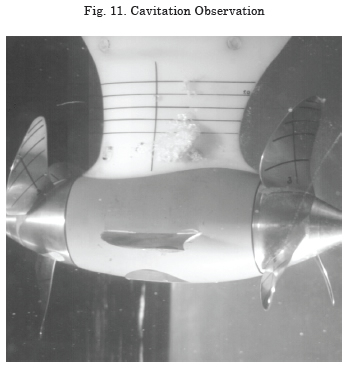
This problem is alleviated, to a certain extent, by the use of TwinPropellers with corresponding power distribution, as the load and pitch of the front propeller acting on the housing stem are considerably lower than with a single, highly loaded pull propeller. To check the cavitation properties, a cavitation test was carried out for the existing standard housing (Fig. 7). For design reasons, the crown wheel is located to the rear; this explains the unusual shape which has, however, proven its worth for normal velocity ranges. The cavitation test revealed that the current standard form is not suitable for high velocity. Fig. 11 shows the suction side of the stem with massive, highly erosive cavitation, which increases still further with oblique inflow. The development process for a new housing was based on these findings. During this process, all necessary disciplines repeatedly passed through several stages:
Housing draft – determination of the hydrodynamic loads in the open-water test with different swivel angles – testing of all mechanical components by means of FEM (strength, weight, availability of parts, mountability…) – strengthening or streamlining as required – revision of the housing contour.
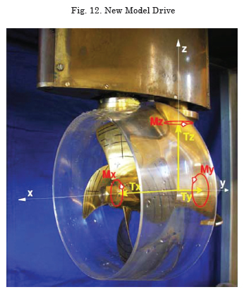
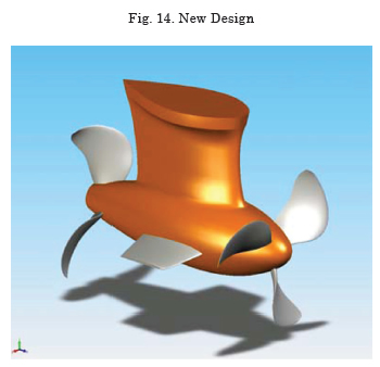
Only this time-consuming procedure could ensure that all limits were exploited to the fullest and that an optimal compromise between mechanical and hydrodynamic demands was achieved. To this end, it is necessary to know the hydrodynamic loads and their dynamic amplitudes with a very high degree of accuracy. For this purpose, a special model drive was developed at the Potsdam Shipbuilding Research Establishment (SVA) that is able to measure separately not only the global forces on the Z-drive, but also the forces and torques on the propellers, the stem, the nozzle, and the mounting and bearing points. Fig. 12 illustrates the principle of this drive and Fig. 13 shows an example of the curve for the torque coefficient with dynamic components during a steering manoeuvre from 0° to 180°.
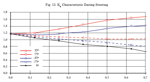
Fig. 14 shows a draft of the new housing shape as a 3D model. Care was taken to ensure that the length of the drive only needs to be increased slightly. Limiting factors here include the need to be able to uninstall the unit upwards with the vessel afloat. It was only possible to reduce the thickness of the stem profiles slightly, so streamlining of the profiles had to consist essentially of stretching the profiles. It was possible to reduce the thickness:length ratio in the central sections by approx. 30% from t/CL = 0.35 – 0.45 to t/CL = 0.26 – 0.30. The design was modified to move the crown wheel from the rear to the front, resulting in a number of positive effects:
• The vertical shaft bearing partially disappears
into the pod itself.
• The stem profile in the connection area
becomes more slender.
• The installation cover on the underwater pod,
which also demonstrated massively erosive
cavitation, can disappear almost completely.
The steering axis of the drive can be moved further towards the leading edge; this means that due to the return torque caused by the larger area behind the rotational axis, the steering torque itself is reduced, despite the enlargement of the surface. The pressure characteristic along the pod and the stem profiles is more harmonious and aligned in the same direction. In the standard housing, the thickness of the stem profiles decreased in the outlet, while that of the pod increased, resulting in an inverse pressure characteristic.
The propeller blades were designed to be positioned on the hub as far away as possible from the stem and systematically adapted to the housing. The front propeller was optimally drafted first, and then the wake field at the location of the rear propeller was measured by laser (LDA) with the front propellers running. The wake field consists of the outflow of the front propeller and the influence of the housing combined. The rear propeller was then adapted and the overall system was tested in open-water, steering and cavitation tests at the Potsdam Shipbuilding Research Establishment.
Results: With an angle of attack of 0° and +/- 10°, the housing is absolutely free from cavitation (Fig. 15). With the exception of a slight tip vortex, the intensity of which depends on the angle of attack, the propellers are also free from cavitation. It was possible to reduce the housing resistance compared with the previous variant, resulting in 68% efficiency at the operating point of the overall system. This excellent value was also confirmed in final tests at MARINTEK in Trondheim.
High velocities of vessels...
• place demanding new requirements on the
flow shape of a Z-drive
• lead to high hydrodynamic loads as a result of high inflow velocity and large profile lengths
• require high-strength mechanical components of low weight and with compact installation
space
• demand the best possible compromise of
hydrodynamic and mechanical requirements.
It is, nonetheless, possible to avoid housing cavitation with relatively little, but intelligent modification work. Comprehensive, all-encompassing tests are required, however. Complex simulations help to reduce the highly time-consuming and costly model tests. The key to success is thorough analysis and coordination of all technical disciplines in the design process.
Distributed Propulsion
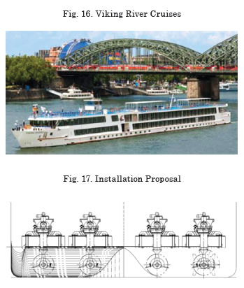
An even more systematic step is the use of multipropeller systems. For river cruisers, which must cope with widely varying operating conditions, one goes a step further and installs four doublepropeller systems instead of two large propulsion systems. These vessels operate in both deep and shallow waters, and both with and against the current. The power requirements and the operating point of the propeller vary greatly. Velocity ranges from 22-23 km/h in deep water to maximum 15 km/h for typical operation in shallow water. Particularly, for this type of operation, considerable power reserves are required. Draught is limited and the need to minimise pressure variation requires sufficient propeller tip clearance. These demands lead to a very small-diameter, but highly loaded propeller and a flexible, requirement-controlled energy management system. The following Figs. 16 and 17 show the installation of four electrically driven STP 200s with a propeller diameter of 1050 mm and a power rating of 4 x 330 kW. Comparable vessels have tow directly powered diesel STP 440s, for example, with a propeller diameter of 1400 mm and a power rating of 2 x 740 kW.
Summary of the principal advantages:
• Approx. 20% lower thrust load coefficient
• 16% lower power requirement in deep water
• 12.5% lower power requirement in shallow
water
• Reduced wear of the main engine, which is always operated at the optimal operating point, avoiding harmful part load
• Longer service life with low load and/or rollingmaintenance
• Significantly greater distance between propeller tips and hull (factor 2)
• First-order pressure variations reduced to 60%
• Reduced extent of the suction side cavitation combined with lower pressure variations for the higher orders
• According to on-board measurements, the significant reduction of the overall pressure variation level resulted in a considerable improvement of the noise level
• Small propulsion systems allow more efficient, resilient mounting with improved damping as a result of the low natural frequency
• Redundancy in the case of failure of a unit
• Lower procurement costs of the smaller propulsion units; use of standard units.
• Reduced risk of grounding in shallow-water operation; yet if grounding does occur, removal and exchange can be carried out anywhere (using a crane) thanks to the low weight, without the need for docking.
Another example is double-ended ferries, which often have high power reserves and multi-propeller systems for reasons of redundancy due to the high wind loads during mooring and casting-off. Loaddependent power distribution fore and aft is highly significant and should be an obligatory part of propulsion tests. Depending on the form of the vessel, active bow propulsion results in very high losses, because the units direct the flow against the hull, destroying thrust. On the other hand, the bow units should not be shut down completely, but generate at least enough thrust to compensate for their intrinsic resistance. If the bow unit only provides little thrust, it is necessarily working with a high propeller advance ratio and, thus, below optimum efficiency. It is therefore useful to have the bow unit generate a certain proportion of the required overall thrust, as this reduces the load on the stern unit, making it more efficient. A sensible compromise is required, which depends both on the operating conditions and on the design of the vessel. A vessel design that takes the thrust losses of the front unit into consideration can significantly improve propulsion efficiency.
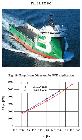
Such concepts are also being considered for special vessels in the offshore industry. The aforementioned aspects apply here; also, although the investment costs for larger systems require different consideration. Nevertheless, reliability, service life and high availability resulting from intelligent maintenance logistics play a decisive role. Diesel-electric propulsion systems are wellestablished in this area. Here, a combination of three propulsion systems is also advantageous. Example of a supply vessel that can be fitted with two or three propulsion units (Fig. 18)
• 8% lower power consumption at operating
speed of 15 kn
• 30% thrust reserves for bad weather
• Maximum speed that can be reached is 16.2 kt
instead of 15 kt
• Longer service life with low load and/or rolling
maintenance
• Redundancy in the case of failure of a unit• Improved manoeuvrability and lower load in DP
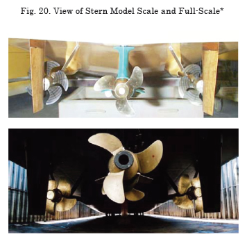
In this connection, a combination of different propulsion systems is also conceivable. The third drive could be a centrally positioned conventional propeller. In this concept, the advantage of high manoeuvrability is coupled with high thrust. One drive configuration that has already been implemented, particularly for fast vessels with high requirements in terms of manoeuvrability, is the installation of an azimuthing propulsion unit as a booster (Fig.20). These vessels have 2 shaft installations (mainly CP propellers) and an additional unit amidships. This offers the following principal advantages:
• The load on the outer units is reduced; this has a positive effect, particularly on noise levels, in the case of fast vessels where comfort is a high priority.
• The maximum velocity of the vessel is
increased.
• There are also clear advantages during manoeuvring at low velocity and during
positioning.
• Improved crash stop manoeuvrability due to the central unit, as the rudder effect of the
main propulsion units is reduced.
Acknowledgement
The author would like to thank Kusch Yacht Projekte GmbH, Germany, for the productive cooperation during the sea trials of the yacht and the enabling of the model test results, including the view from stern of the model.
References
HANDBUCH DER WERFTEN, Band XIII, Schifffahrts-Verlag “Hansa“, Hamburg, 1976, ISBN 3-87700-017-7
J.P.BRESLIN AND P. ANDERSEN. Hydrodynamics Of Ship Propellers, Cambridge Ocean Technology Series 3, Cambridge University Press 1994.
SVA-Report 3093, Freifahrtversuche mit dem SCD2020, Potsdam 2005, unpublished.
SVA-Report 19/3160, Kavitationsversuche mit dem SCD2020, Potsdam 2005, unpublished.