Ship maneuverability: full-scale trials of colombian Navy Riverine Support Patrol Vessel
Maniobrabilidad de buques: pruebas a escala real del Buque Patrullero de Apoyo Fluvial de la Armada de Colombia
Jorge E. Carreño Moreno1
Etty Y. Sierra Vanegas2
Victor H. Jiménez González3
Abstract
Methodology and results of full scale maneuvering trials for Riverine Support Patrol Vessel “RSPV”, built by COTECMAR for the Colombian Navy are presented. This ship is equipped with a “Pump – Jet” propulsion system and the hull corresponds to a wide-hull with a high Beam – Draft ratio (B/T=9.5). Tests were based on the results of simulation of turning diameters obtained from TRIBON M3© design software, applying techniques of Design of Experiments “DOE”, to rationalize the number of runs in different conditions of water depth, ship speed, and rudder angle. Results validate the excellent performance of this class of ship and show that turning diameter and other maneuvering characteristics improve with decreasing water depth.
Key words: maneuverability, shallow waters, sea trials, ship dynamics.
Resumen
En el presente trabajo se presenta la metodología y los resultados de las pruebas de maniobrabilidad a escala real del Buque Patrullero de Apoyo Fluvial Pesado “PAF-P”, construido por COTECMAR para la Armada Nacional de Colombia. El buque está equipado con un sistema de propulsión de bomba de agua tipo “Pump – Jet” y su casco corresponde a un casco con una relación Manga – Calado muy alta (B/T = 9.5). Las pruebas se basaron en los resultados de simulación de círculos evolutivos obtenidos en el software de Diseño TRIBON M3©, aplicando técnicas de Diseño de Experimentos “DOE”, para racionalizar el número de corridas en diferentes condiciones de profundidad, velocidad y ángulo de timón. Los resultados validan el excelente desempeño de esta clase de buques y muestran que el diámetro de giro y otras características de maniobrabilidad mejoran con la disminución de la profundidad.
Palabras claves: maniobrabilidad, aguas poco profundas, pruebas en mar, dinámica del buque.
Date Received: November 26th, 2010 - Fecha de recepción: 26 de Noviembre de 2010
Date Accepted: January 20th, 2011 - Fecha de aceptación: 20 de Enero de 2011
________________________
1COTECMAR. Oldenburg, Lower Saxony. Germany. e-mail: jorgec@cotecmar.com
2COTECMAR. Cartagena, Bolívar. Colombia. e-mail: esierra@cotecmar.com
3COTECMAR. Cartagena, Bolívar. Colombia. e-mail: vjimenez@cotecmar.com
............................................................................................................................................................
Introduction
The Colombian Science and Technology Corporation for the Development of the Naval, Maritime, and Riverine Industry (COTECMAR, for its name in Spanish) designed and constructed a series of Riverine Support Patrol Vessels “RSPV” for the Colombian National Navy to comply with missions in over 13,000 Km of the nation’s navigable rivers. The first and second generations of these vessels, are comprised of four units equipped with propulsion systems consisting of two propellers driven by diesel engines and a steering system composed of two compensated rudders. These vessels fulfill missions in Tropical rivers, characterized by a wide course, without canalization or marked, with very shallow waters, especially during dry season months, so much that the depth – draft (h/T) ratio may be reduced to 1.5.
The first vessel of the series, “ARC GUILLERMO LONDOÑO” was commissioned in January 2000 and the fourth vessel started operations in 2004.
The operational experience gathered with these vessels evidenced the need to introduce different technologies for the propulsion and steering of these vessels. Propellers with a minimum immersion generate pressure pulses transmitted through the sternpost to the vessel structure, not only causing harmful effects to equipment and less rigid structures, but deteriorating crew comfort conditions; likewise, objects floating on river waters like tree trunks frequently become strong causes of damage, by deforming the propeller blades and the rudders. Also, conditions of maneuverability of vessels with very high beam - draft ratios (B/T=9.5) are critical because there is route instability, a situation exacerbated by navigation in very shallow waters with presence of currents.
This prior problem, as well as the review of the roles and operational capacities of the RSPV vessels called for re-engineering, which began during September 2003 with trials in the hydrodynamic experience towing tank at the “Centrum Techniki Okretowej” (CTO) in Gdansk, Poland, where resistance trials were developed on the vessel’s advance under different depth conditions, along with self-propulsion tests with a new type propulsion configuration -Pump Jet-.
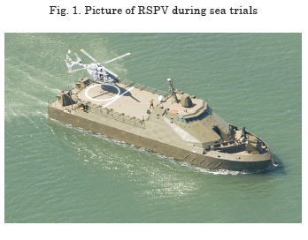
The third generation RSPV (Fig. 1) comprises four vessels, the first of which was commissioned in 2005 and the last two in March 2009. Improvements in terms of maneuverability and reliability of the propulsion and steering system are evident, on one part the appendages are totally eliminated such as buttresses, propellers, axes, and rudders, which implies that there are no possibilities of damage due to impact with floating objects; while the possibility of independently controlling water jets from each pump in any direction confers exceptional maneuverability conditions to the vessel in terms of ease of turning and change of course, tactical ability – important during combat to aim its weapons through the appropriate flank; despite the aforementioned, routing instability persists, that is, the coursekeeping ability because of the low drift area (L x T) and the lack of control surfaces.
Bearing in mind the existing problem, the “Sea trials” Project was undertaken in which one of the objectives was to run full-scale trials on the RSPV to identify its maneuverability characteristics, following the vessel maneuverability standards, adopted by the International Maritime Organization (OMI) and issued by resolution A. 751 (18) in 1993 [5], in addition to circular MSC/Circ.644 published in June 1994 [6]; the maneuverability characteristics, issued by the OMI, are typical measurements with nautical interest in vessel performance.
To assess these qualities, the OMI recommends performing turning circle trials, zig-zag trials, and stop collision tests; however, the referred standards do not cover all types of vessels or the operational circumstances in which some of them navigate. Particularly, in 2006 the European Union adopted directive Nº 2006 C/166-E/01 [3], which establishes the requirements of maneuverability that must be complied with by vessels navigating the European riverine network and these are summarized in the stopping ability, back-up ability, ability to execute evasive maneuvers, and ability to turn against the current.
The full-scale sea trials were conducted by COTECMAR, on board the “ARC STCIM EDIC CRISTIAN REYES HOLGUÍN”, the last vessel of the third generation RSPV, in the Cartagena Bay on the Colombian Caribbean Coast, during March and April 2009 in shallow waters (h/T = 2.2) and deep waters (h/T = 24). The vessel was subjected to turning circle trials at different approach velocities and rudder angles, zig-zag, and emergency stop; the instrumentation used during the trials included a Differential Global Positioning System (DGPS), an inertial gyro, sensor transmitters of thrust direction of propellers, vane and anemometer, a pair of optical sensors to measure angular velocity of the axes, and a torque measurement system. The data sensed were acquired through virtual instruments developed via LabVIEW for this purpose, centralizing the information in a computer located on the ship’s bridge.
Description of the Vessel
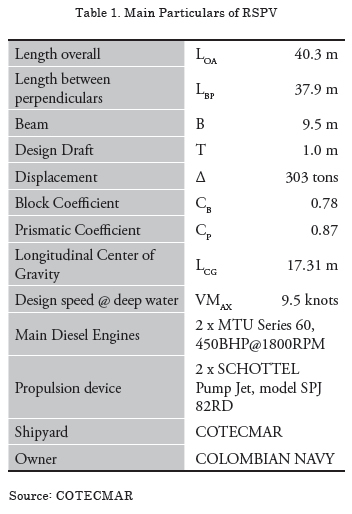
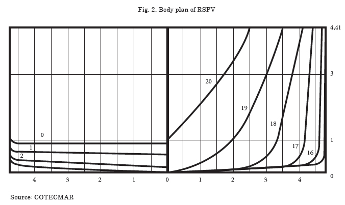
The main characteristics of the RSPV are described in Table 1. The hull corresponds to a river vessel with very little dead-rise and high beam - draft ratio, designed to navigate in very shallow waters, the frame box is shown in Fig. 2.
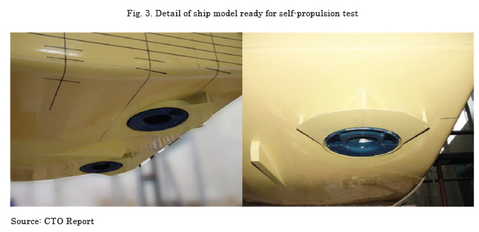
Fig. 3 shows in detail the disposition of the propellers on the model ready for the self-propulsion test; as noted, the pumps are placed on the vessel sternpost and there are no exposed surfaces. The hull has no appendices except for a central skeg that permits separating the flow of water in each pump, as well as two deflector plates that guide the pumps output flow and contribute to diminishing the thrust deduction.
The propulsion system is composed of two “Pump – Jet” type centrifuge pumps model SPJ 82RD, manufactured by Schottel, driven by MTU diesel engines Series 60 450BHP@1800RPM with a connection composed of an investor reduction gear and a cardan shaft. The jet from the pumps may be aimed 360 degrees individually or in tandem through a joy stick control from the bridge or locally from the engine control room.
Experimental Design
The number of runs and the cost represented by experimenting with a vessel at full scale exceeds the resources available and make it non-viable. Making use of experimental design methodology and twolevel fractional factorial design, Montgomery [13], the experimenter may reasonably suppose that certain higher order interactions are insignificant, permitting them to obtain information from the main effects and from the lower order interactions running only one fraction of the complete factorial experiment.
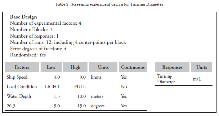
Following the same methodology introduced by Islam et al., [8], herein present the screening experimental design to conduct the sea trials for the turning circle maneuver. First of all, a dimensional analysis has been made of the main factors intervening in the maneuver mentioned, bearing in mind the interest of studying the influence of the navigation in shallow waters, the objective is to identify the most significant factors, so they can be eliminated to – in a later stage – rationally design the experiment with the remaining factors. Table 2 shows the screening design characteristics conducted via STATGRAPHICS Centurion XV© Version 15.2.14 software.
For the purpose of evaluating the linearity of the effect of the factors, four central points per block has been aggregated, yielding a 2k-1 design, i.e., 24-1, 8 runs plus four central points for a total of 12 random runs. It has been intentionally omitted the maneuver execution flank factor, which was introduced during the final design phase of the experiment. The reason is that it is not possible to obtain a variation in the response from simulation with the TRIBON-M3© software, which has been used to obtain the turning diameter values.
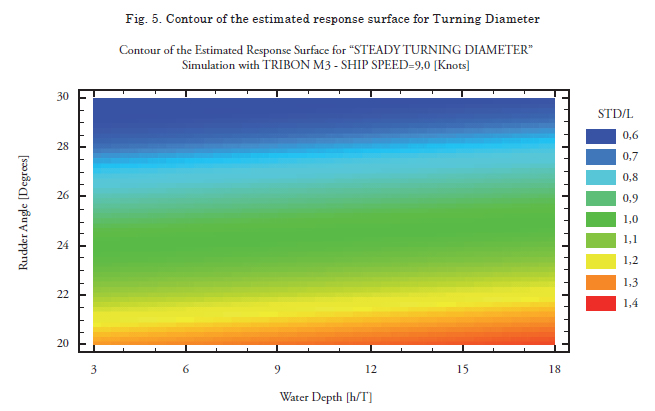
The contour of the response surface estimated for the turning diameter is shown in Fig. 5; this result has been obtained from simulation in TRIBON M3© using the mathematical models of filled form vessels and equipped with conventional rudders and propellers, given that there was no calculation tool to predict maneuverability characteristics of vessels with non-conventional, Pump-Jet type propulsion and steering systems. The models used in this software correspond to the work developed by Khattab [11], who developed multiple regressions to find the linear and nonlinear hydrodynamic derivatives in deep and shallow waters, for filled form vessels. It was noted that for a velocity of 9 knots, the turning diameter diminishes as depth is diminished, that is, the maneuverability characteristics improve contrary to what occurs with most vessels.
This disagrees with the widely known literature for vessels of conventional proportions and equipped with propellers and rudders. Kijima (2003) [12] presents results of turn simulations in shallow waters for four different vessels and in all instances, the turning diameters and tactical diameters increase as depth diminishes. Delefortrie (2007) [2] has studied the effect of the under keel clearance in container ships and validates the increase in the dimensions of the vessel’s turning diameter as the under keel clearance diminishes. The Maneuverability Committee (2002) of the 23rd International Towing Tank Conference (ITTC) [9], presented the effects of depth on standard maneuvers, describing an increase of up to 75% of the tactical diameter in vessels navigating with an under keel clearance of 20%. There are few results of full-scale maneuvers in shallow waters; this added to the specifics of the propulsion system and to the hull geometry makes the present experiment particularly important for the scientific community.
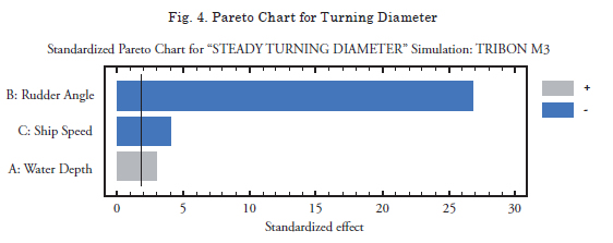
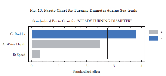
The statistical analysis of the two-level fractional model with four central points focuses on gathering the most significant factors in the response, according to that presented in Table 2. Fig. 4 shows the Pareto diagram, which can be used to identify the most significant factors. In the case study, were eliminated the second, third, and fourth-level interactions, as well as the load factor. The velocity factor was maintained to give the experiment greater robustness.
The three significant factors studied are: Rudder angle, vessel velocity, and depth. Likewise, and as required by IMO norms, a factor generator of random errors will be included to design the final experiment. This factor will be the flank on which the maneuver is executed, that is, starboard or port.
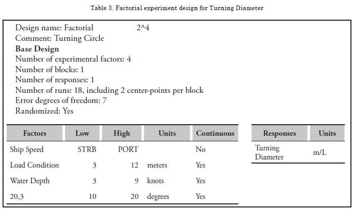
The design of the 2k factorial experiment is shown in Table 3, with two central points and four factors, i.e., 18 runs in total. This process permitted eliminating a factor and insignificant interactions, as well as optimizing the number of runs against what was initially sought through a design with three factors of three levels each (Velocity, depth, and rudder), along with two discrete factors with two levels each, that is, load condition and flank of the maneuver. In total, the number of runs was reduced from a value of 108 (33 x 2 x 2) to merely 18.
The number of runs defined in Table 3 is justified from the scientific interest point of view of the present research to validate the mathematical models of vessel maneuverability with nonconventional propulsion systems navigating in shallow waters. The low and high values of the factors described differ from those shown in Table 2 for practical reasons. In the case of depth, it is conditioned by the area where the maneuvers take place within the Cartagena Bay, finding only constant depths between 2 and 3 meters, for ratios of h/T = 2.2 and depths greater than 13 meters for the case of ratios of h/T > 10 in which it is considered that there is no canal effect. Similarly, before the formal start of the tests, It was decided to increase the angle of incidence of the water jet from the pumps, increasing it from 10 to 20 degrees, given that there is no significant response effect upon the vessel with lower angles.
Recommended Maneuverability Trials
The maneuverability trials seek to determine vessel behavior in the change or coursekeeping ability, route stability, and ease of turn; said features can be evaluated quantitatively given that they are directly related to the magnitudes measured during the execution of the trials.
SNAME [15] has conducted sea trials to evaluate maneuverability; in 2002, IMO adopted Resolution MSC 173(76) which exposes the standards and maneuverability characteristics that must be complied with by each vessel. That same year, ITTC exposed three documents containing the procedures to conduct full-scale sea trials of vessels and in 2006 the European Union adopted directive Nº 2006 C/166-E/01 which established the maneuverability requirements to be complied by vessels navigating the European riverine network.
According to the final report and recommendations to the 22nd ITTC (2005), among the maneuverability trials recommended by several organizations, COTECMAR selected zig-zag, turning circle, reverse spiral, and emergency stop to evaluate maneuverability in the RSPV “ARC STCIM Edic Cristian Reyes Holguin”.
Data Acquisition System
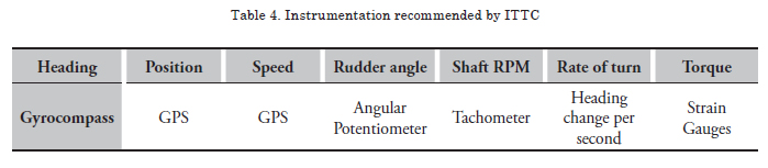
Data acquisition during the sea trials was conducted in distributive way by using different types of sensors, integrated in centralized and synchronized way through a portable computer and data acquisition and digitization cards. The data obtained from the acquisition system were sampled according to ITTC recommendations (0.5 - 2 samples per second); these are stored in the computer for post-processing and to obtain information on the maneuverability characteristics of the vessel by quantifying the evaluation parameters. Table 4 specifies the instrumentation recommended by ITTC [9] and [16].
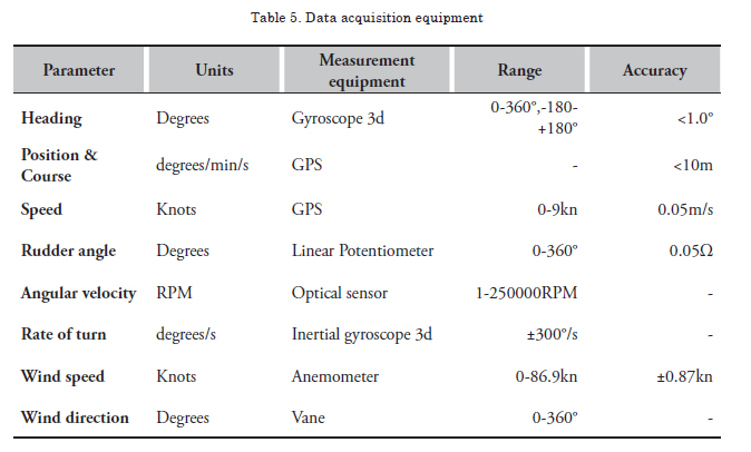
The instrumentation used to carry out sea trials in COTECMAR (Table 5), selected according to ITTC recommendations, can provide a time history of the measurements during the execution of the maneuvers.
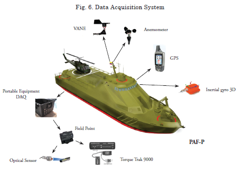
Data corresponding to time, heading, course, position, speed, and rate of turn are gathered from the bridge; while torque and angular velocity of propeller shafts, direction and wind speed are collected from the engine room. The sensors, interfaces, and input sources installed in the engine room are integrated on portable equipment that permits the connections of the equipment required for each trial and which also has wireless or cable communication with the PC located on the bridge. The data acquired are collected by using an application developed via LabVIEW. Fig. 6 shows the location of the instrumentation used in the RSPV sea trials.
Performance of the Experiment
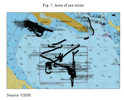
COTECMAR conducted full-scale sea trials on the “ARC STCIM EDIC CRISTIAN REYES HOLGUÍN”, last vessel of the third generation of RSPV, in the Cartagena Bay on the Colombian Caribbean Coast (Fig. 7) during March and April of 2009 in shallow waters (h/T = 2.2) and deep waters (h/T = 24). The tests on 6-m depths, corresponding to the two central points defined in the experimental design, were not possible because of difficulties in finding a safe navigation zone within the Cartagena Bay.
The selection of the area for sea trials was carried out by the Hydrographic Area of the Colombian National Navy’s Center of Oceanographic and Hydrographic Research (CIOH, for its name in Spanish), who also participated in conducting the tests with the acquisition of position data by using a Differential Global Positioning System (DGPS) and then providing trajectory images and data of the tests processed by using the HYPACK software, high-precision information used in data validation.
HYPACK is a hydrographic software that integrates the necessary tools for each of the hydrographic survey stages1; CIOH carries out marine depth surveys under the single-beam system, with an echo-probe and a DGPS complemented with the HYPACK MAX package, generating a relief map of the seafloor with useful information for surface navigation. HYPACK MAX permits configuration of geodesic parameters (zone, ellipsoid, geoid model) so that it provides the position data in geographic and plane coordinates; for the calculations necessary to analyze maneuverability, it is more convenient to use the data in plane coordinates.
Data Processing
The following was the procedure for data processing:
1. Data filtering: it is the first item performed in the information analysis procedure, considering that there is always noise included in the signals acquired. Tool used: Microsoft Excel (Mathematical Software).
2. Synchronization over time of data acquired: carried out to synchronize over time the data acquired by the COTECMAR data acquisition system with data acquired by CIOH (DGPS). Tool used: Microsoft Excel.
3. Interpolation: carried out on files of incomplete data in fractions of time. Tool used: Microsoft Excel.
4. Smoothing of data acquired to analyze some signals that were more affected by noise, signals like drift and yaw rate. Tool used: STATGRAPHICS Centurion XV© Version 15.2.14.
5. Synchronization of data with the initial test heading is necessary to start the information analysis.
6. Identification of critical points, bearing in
mind information of speed, heading, and
balance.
• Start of maneuver
• Rudder order
• 90° heading variation
• 180° heading variation
• Complete maneuver or start of spiral
7. Correction for wind and current according to recommendations by the OMI “Resolution A. 751(18), 1993” [5] for maneuvers whose trajectories were deformed by the effects of wind and current during tests.
8. Graphing the time series that describe vessel behavior during tests, under transitory and steady state, for speed, heading, course, drift, yaw rate, and roll. Tool used: Microsoft Excel.
9. Calculation of variables: turning diameter, tactical diameter, advance and transference; necessary to conduct the analysis of vessel ease of turn and change of course.
10. Graphing the path followed by the vessel in each test, taking into account that the information of position per second corresponds to plane coordinates, it was only necessary to translate and rotate the trajectory. Tool used: Microsoft Excel.
11. Processing and analysis of images from videos taken during tests to extract heading information in instances where it was not possible to obtain such by means of the gyroscope and validate it in cases in which it was possible to acquire said information. Tool used: Boat_Tracking2 [17].
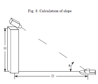
Processing of video image analysis consists in tracing a straight line between two points located on the image of the vessel, one on the bow and another on the stern, the angle of this line with respect to the cardinal points would be the heading of the vessel if the videos had been made on the horizontal plane; however, given that the videos were filmed from a building, the straight line (with determined position) determining the heading of the vessel, is found on another reference heading and, thus, the straight line is defined by the heading, as well as a slope. To measure the heading, it was necessary to find the projection of the horizontal plane in real magnitude and in consequence of the “θ” slope (Fig.8). Once the slope is found, the horizontal projection can be made and the heading value can be found via Equation 2.
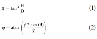
Where ![]() and
and ![]() are measured in the video as the components of the straight line traced between the vessel’s bow and stern.
are measured in the video as the components of the straight line traced between the vessel’s bow and stern.
12. Graphing response surfaces and Pareto diagrams for variables of turning diameter, tactical diameter, advance, and transference. Tools used: STATGRAPHICS Centurion XV©.
Nomenclature and Reference System
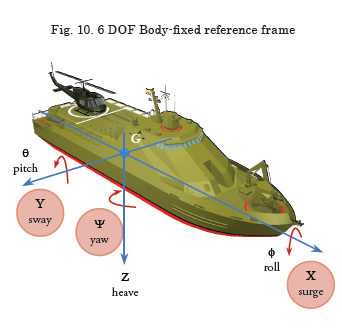
The nomenclature and the reference system described by the IMO in the MSC/Circ.1053, Appendix 1 were used in this research. The mathematical models of vessel dynamics consider the forces acting along the vessel, separated by their components in each axis of the fixed-coordinate system on the G body (XY). The vessel’s six degrees of freedom are defined by the linear velocities (u,v,w) and by the angular velocities (p,q,r). For this study, it was sufficient to consider three degrees of freedom on the G plane (XY), the vessel moved forward in the “X” sense, with a u velocity (surge), on the flank in “Y” sense, with a v drift velocity (sway) and rotate around the “Z” axis with an r yaw velocity. Fig. 10 shows the vessel’s six degrees of freedom, highlighting those considered in the present research.
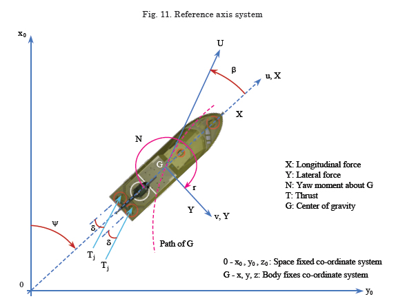
The vessel’s turning circle maneuver, as shown by Fig. 9 and Fig. 11, is carried out on the X0Y0 plane; the origin of this system coincides over time t=0, with the longitudinal position of the vessel’s center of gravity “G”. The X0 axis is aimed north, i.e., time zero coincides with the heading (ψ); hence, drift does not exist (β=0) and the course coincides with the vessel’s heading (χ = ψ). Once the rudder order is given, the vessel’s heading deviates from the vessel’s advance direction, with a drift appearing when the vessel describes a circular trajectory. The following are the velocities and angles describing the trajectory and orientation of the vessel:
U : Advance speed
u : Surge in X sense
v : Sway in Y sense
r : Yaw in N sense (angular velocity)
β : Drift angle
ψ : Heading, defines the direction of the vessel’s bow
χ: Course, defines the direction of the trajectory of the vessel’s Center of Gravity
δ: Rudder angle
The equations that define the kinetics of the turning circle maneuver are as follows:
Ship speed:
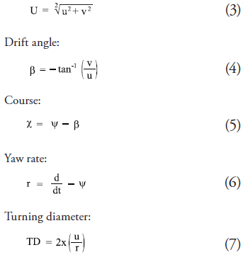
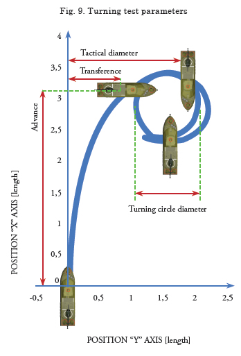
The turning circle is the maneuver conducted on one or another band, starboard and port, with 35° of rudder, or the maximum rudder angle admissible to the trial speed “U”, from a straight line approach without heading oscillations. For the case study, It was defined a maximum 20° rudder angle. The main parameters measured in this trial are shown in Fig. 9 and are described next:
1. Advance is the distance covered in the direction of the original course by the midpoint of vessel O, from the position in which the rudder order is given, until the position in which the bow direction has changed 90° from the original heading.
2. Tactical diameter is the distance covered by the midpoint of the vessel from the position in which the rudder order is given, until the bow direction has changed 180° from the original heading.
3. Transference is the distance covered in perpendicular sense to the original course from the position in which the rudder order is given, until the position in which the bow direction has changed 90° from the original heading.
4. Turning diameter in steady state is an important measurement that is verified once the drift, forward speed, and yaw rate become constant and the vessel is describing a circular trajectory.
Results of trials
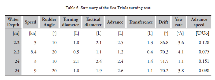
Table 6 presents a summary of the results of the full-scale trials carried out on the “ARC STCIM EDIC CRISTIAN REYES HOLGUÍN”, after correcting for wind and current; It was considered the average of the results of pairs of maneuvers executed under similar circumstances (equal depth, velocity, and rudder angle) but on different flank, contrasting the results between trials conducted in shallow waters and those conducted in deep waters.
During turning circle trials, It was evaluated the vessel’s turning ability, which was considered satisfactory according to IMO if it complied with the following criteria: the values of the results of trials for tactical diameter must be less than 5 L, consider the set of results in Table 6 (2.1 L, 1.1 L, 2.4 L, 1.9 L); additionally, the advance values of the results must be less than 4.5 L, consider the set of results (2.5 L, 1.2 L, 2.4 L, 2.6 L); according to said results, note that the vessel complies with ITTC criteria and, hence, its turning ability is considered satisfactory.
The vessel’s turning ability was influenced by the depth of the area of navigation, due to changes in the magnitudes of the hydrodynamic forces and moments acting on the hull and by action of the thrust force and steering generated by the propulsion system. The vessel’s turning ability was quantitatively evaluated from the results of the turning diameter, tactical diameter, advance, and transference, whose values, for the case study, diminish as water depth diminishes (Table 6), also the velocity; while values of turn rate increase with diminished depth. In the maneuvers reported at 20 degrees of rudder angle no significant change in the drift angle value was observed in the steady state upon varying depth; nevertheless, it was very high.
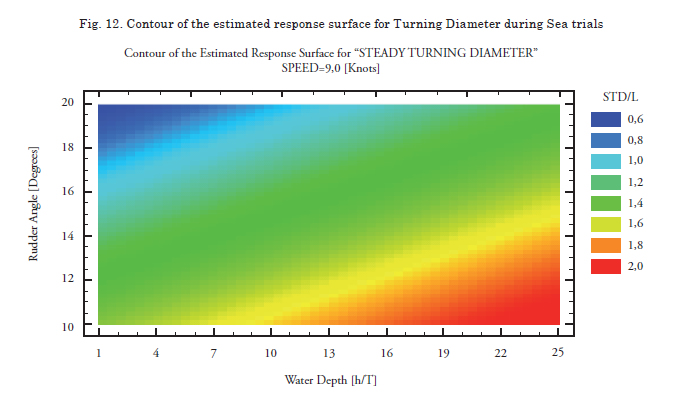
The contour of the response surface estimated for the turning diameter, processed from the full-scale trials, for advance speed of 9.0 knots, is shown in Fig. 12; evidently, there is improved ease of vessel turn in shallow waters, the effect is even more pronounced than that shown by results simulated with TRIBON M3©, as observed in Fig. 5. Also, Fig. 13 reports the Pareto diagram with the significance of the experimental factors, It is notice that “Water depth” has an effect in the same sense on the “Turning diameter”, this effect although in the same sense is much more pronounced than that obtained via simulation with TRIBON M3© (Fig. 4).
The same effect was reported in 1988 by Yasuo Yoshimura and Hitoshi Sakurai, as a result of the study of the maneuverability qualities in shallow waters, conducted with double propeller and double rudder vessels, one wide beam and the other conventional [18].
Similarly, the ITTC – through its 25th committee – reported the same effect due to shallow waters, known as NS type. The results of the study by Yasukawa and Kobayashi in four different models of vessels in shallow and deep waters reported the NS effect, which indicates that the turning diameter for the turning circle trial is smaller as water depth diminishes [10]. This phenomenon is attributed to the increased steering forces generated by the rudder as depth diminishes.
For the case study, given that the RSPV vessel is not equipped with rudders; rather, the steering force is obtained from the direction of the water jet from each of its pumps. It is relevant to assess these forces, as well as their equilibrium with the hull’s hydrodynamic forces under different depth conditions. This will be possible in a future investigation, which permits validating a mathematical model based on the time series, trajectories and records taken during full-scale experimenting.
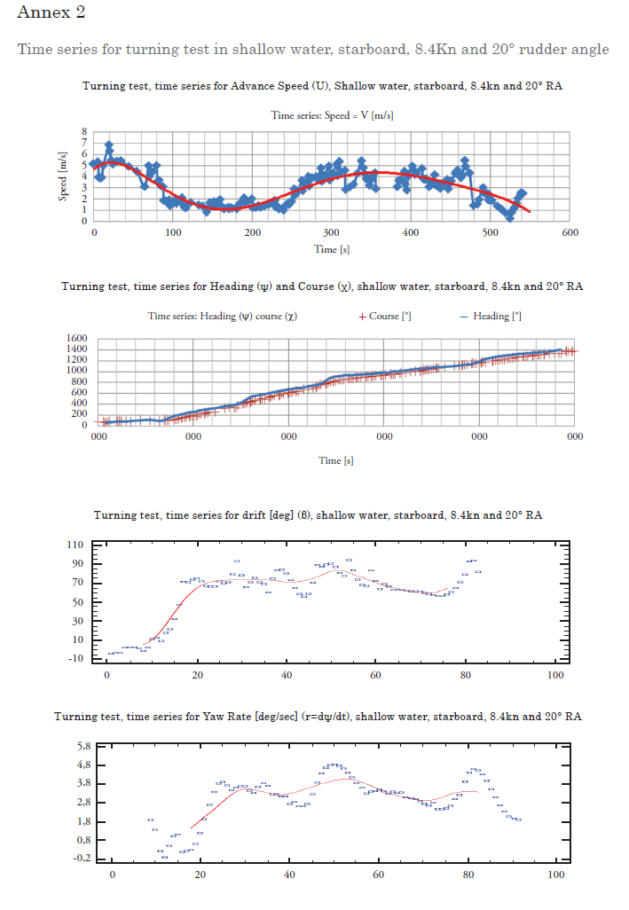
Annex 1 shows the time series of velocity, heading, course, drift, and yaw rate for a maneuver in deep waters (h/T=24) at starboard with 20 degrees of rudder angle and a speed of 9 knots. While Annex 2 shows those corresponding to a maneuver in shallow waters (h/T=2.2) at starboard with 20 degrees of rudder angle and a speed of 8.4 knots.
The time velocity series show the inflection points, indicating the change of maneuver state (vessel entrance to the maneuver, passage to transitory state, and finalization in steady state).
In the time heading and course series, it may be noted that the heading signal responds before than the course signal, because of the rudder action and the external current and wind forces; thereby, the vessel’s bow deviates its trajectory with respect to the heading, generating a drift angle.

Conclusions
The RSPV vessel fully complies with the IMO standards regarding the ability to changing heading, which was demonstrated by conducting turning circles under conditions of deep waters and 20° rudder angle.
It has been demonstrated that the RSPV vessel’s ability to changing heading improves with diminished depth, this is evidenced by diminished turning diameters, advance, and transference when going from depths h/T=24 to shallow waters with h/T=2.2; i.e., it is reported the NS type effect described by Yoshimura and Sakurai in 1984.
It was proved that simulation with mathematical models requires an experimental base that permits adjusting the hydrodynamic forces, as well the interactions among the hull, propulsion systems and steering systems; hence, this work provides elements to validate these models.
Excellent performance is proven regarding the ability to change of heading in vessels equipped with steerable propulsion systems, which provide thrust in any direction; with a 10° angle the RSPV vessel complies with the IMO standards for the turning circle maneuver.
It has been proven the benefit of using experimental design techniques to rationalize resources and obtain quality data covering experimental factors during the previously defined low and high limits, reducing the number of runs from 108 to 18 during full-scale experiments with vessels.
It has been developed and implemented a procedure to validate the vessel’s trajectory and the drift angles measured during the trials through digital image analysis.
Acknowledgments
The authors thank the following institutions and individuals for their valuable contributions for the development of this work:
The Colombian National Navy, for making available for the research team the vessel “ARC STCIM EDIC CRISTIAN REYES HOLGUÍN” with its crew and for having provided logistics support required to conduct the trials.
Ship Lieutenant Commander Nicolás Romero and Crew of the “ARC STCIM EDIC CRISTIAN REYES HOLGUÍN” for the enthusiastic participation during March and April of 2009 while conducting maneuverability experiments.
The Colombian National Navy’s Center for Oceanographic and Hydrographic Research (CIOH) for technical and human support while conducting the trials, by providing the data processing and measurement system to validate trajectories, as well as selecting the area of operations during March and April of 2009.
Students, Navy Lieutenant Carlos Augusto Estévez Duran and Navy Lieutenant Carlos Enrique Hernández Cruz, who developed in 2008 a “Methodological Guide” within the framework of the present research, thesis required for the degree of Naval Engineer issued by the “Almirante Padilla” Naval School.
Doctor Marcos Sanjuán, professor at Universidad del Norte in Barranquilla, who contributed the necessary knowledge for the authors to carry out the Experimental Design within the framework of cooperation between that University and COTECMAR during the second semester of 2008.
Mr. César Mauricio Quimbaya Sarmiento, who during his industrial practices at COTECMAR as an Electronics Engineering student from Universidad Central in Bogotá during 2008 developed his thesis for the degree of Electrical Engineer, within the framework of the present project, in the conceptualization and preliminary design of the data acquisition system.
Mr. Juan Esteban Villegas, Mechatronics Engineering student from the Antioquia School of Engineering, who during his industrial practices at COTECMAR during the first semester of 2011 worked in processing the digital images to validate trajectories and drift angles.
References
[1]. CARREÑO, J.E. Proyecto de Tesis Doctoral. 2006. Universidad Politécnica de Madrid, Escuela Técnica Superior de Ingenieros Navales.
[2]. DELEFORTRIE, G. and VANTORRE, M. Modeling the Maneuvering Behavior of Container Carriers in Shallow Water. Journal of Ship Research, No. 4, Vol. 51, December 2007, p. 287–296.
[3]. DIRECTIVA DEL PARLAMENTO EUROPEO Y DEL CONSEJO. Directiva Nº 2006 C/166-E/0. 2006.
[4]. GUEDES, C. FRANCISCO, R.A. MOREIRA, L and LARANJINHA, M. Full-Scale Measurements of the Maneuvering Capabilities of Fast Patrol Vessels, Argos Class. Marine technology, No 1, Vol 41, January 2004, p.7-16.
[5]. IMO. Interim Standards for Ship Maneuverability, Resolution A.751 (18), Nov 1993.
[6]. IMO. Explanatory Notes to the Interim Standards for Ship Maneuverability. Resolution MSC/Circ.644, June 1994.
[7]. IMO. Standard for Ship Maneuverability. Resolution MSC. 137(76), 2002.
[8]. ISLAM, M. Combined use of dimensional analysis and modern experimental design methodologies in hydrodynamics experiments. Ocean Engineering 36, (2009), p. 237–247.
[9]. ITTC MANOEUVRING COMMITTEE. Recommended Procedures. Full Scale Measurements Maneuverability, Full scale Maneuvering Trials Procedure. 2002.
[10]. ITTC MANOEUVRING COMMITTEE. Final Report and Recommendations to the 25th ITTC. 2008.
[11]. KHATTAB, Omar. Multiple regression analysis of the hydrodynamic drifttives for manoeuvring equations. British Ship Research Association, December 1984.
[12]. KIJIMA, K. LEE, S. FURUKAWA, Y and NAKIRI, Y. Ship Manoeuvring Characteristics as Function of Ship Form in Shallow Water. In: Maritime Institute. International Conference on Marine Simulation and Ship Maneuverability MARSIM. June 2006.
[13]. MONTGOMERY, D. C. Diseño y análisis de experimentos, Segunda Edición, Limusa Wiley. 2004.
[14]. SIERRA, E.Y. Diseño y construcción de un equipo portátil que integre los elementos utilizados para las pruebas de mar y estudio de incertidumbre de las medidas, basado en normas y estándares internacionales. Cartagena de indias D.T. y C.2008. Trabajo de grado (Ingeniera Electrónica). UTB. Facultad de ingeniería eléctrica y electrónica.
[15]. SNAME. Guide for Sea Trials. Technical and Research Bulletin N° 3-47, 1989.
[16]. THE SPECIAL COMMITTEE ON TRIALS AND MONITORING. Final report and recommendations to the 22nd ITTC. 2005.
[17]. VILLEGAS, J.E. Herramienta de análisis de videos para apoyar los procesos de recopilación de datos en pruebas de mar. Cartagena de Indias, Julio de 2011.
[18]. YOSHIMURA, Y and SAKURAI, H. Mathematical Model for the Manoeuvring Ship Motion in Shallow Water (3rd Report: Manoeuvrability of a Twin-propeller Twinrudder ship). KSNAJ, Vol 211, March 1988, p.115-126.
1HYPACK MAX (single-frequency echo-probes), HYSWEEP (multi-beam echo-probes). DREDGEPACK (dredging), planning and design of the work, acquisition, and editing of data, final product (volumes and plotting)
2Constructed under an environment based on Java “Processing”, the software analyzes the heading of the vessel during sea trials.