Electric Arc Spray Coatings for the Naval Industry
Recubrimientos producidos por Proyección Térmica por Arco para aplicaciones en la industria naval
Laura Marcela Dimate Castellanos1
José Alfredo Morales Torres2
Jhon Jairo Olaya Florez3
Abstract
Carbon and stainless steel, as well as Fe-Nb-Cr-W coatings were deposited on steel substrates by using electric arc spray, and its possibility of applying such coatings in the naval industry was analyzed. In order to achieve this, the coating microstructure was characterized before and after the corrosion, abrasive wear, and thermal barrier tests. Corrosion resistance was analyzed via potenciodynamic polarization test using a NaCl electrolyte at 3%; abrasive wear resistance was measured by using a three-component system following ASTM G-65 recommendations, while quality control as thermal barriers was studied by using EIS tests. Scanning Electron Microscopy, optical microscopy and X-ray diffraction were used to characterize the microstructure of the coatings.
Key words: Electric arc spray, abrasive wear, thermal barrier, corrosion.
Resumen
Recubrimientos de acero al carbono, inoxidables y aleaciones de Fe-Nb-Cr-W fueron depositados sobre sustratos de acero mediante la técnica de proyección térmica por arco y se estudió la capacidad de dichos recubrimientos para ser aplicados en la industria naval. Para ello, se caracterizó la microestructura antes y después de los ensayos de corrosión, desgaste y térmicos en los recubrimientos producidos. La resistencia a la corrosión fue evaluada mediante ensayos electroquímicos de polarización potenciodinámica utilizando un electrolito de NaCl al 3%, la resistencia al desgaste abrasivo fue medida usando un sistema de tres cuerpos siguiendo las recomendaciones de la norma ASTM G-65 y para estudiar el estado y control de calidad de las barreras térmicas se utilizó la técnica de espectroscopia de impedancia electroquímica.
Palabras claves: Proyección térmica por arco, desgaste abrasivo, barrera térmica, corrosión.
Date received: September 24th, 2010 - Fecha de recepción: 24 de septiembre de 2010
Date Accepted: October 29th, 2010 - Fecha de aceptación: 29 de octubre de 2010
________________________
1Universidad Nacional de Colombia. Departamento de Ingeniería Mecánica y Mecatrónica. Colombia. E-mail: lauramdimate@hotmail.com
2Corporación de Ciencia y Tecnología para el Desarrollo de la Industria Naval, Marítima y Fluvial - Cotecmar. E-mail: amorales@cotecmar.com
3Universidad Nacional de Colombia. Departamento de Ingeniería Mecánica y Mecatrónica. Colombia. E-mail: jjolaya@unal.edu.co
............................................................................................................................................................
Introduction
Thermal spray as a recovery process has its origin early in the 20th century with the invention of the Schoop-Günther metallization process in 1917 [1]. This process was first applied to materials with low melting points, such as Tin or Lead, and was later extended to refractory metals and ceramics. It is one of the most versatile techniques for the application of coating materials used in protecting mechanical components from abrasive wear, adhesion, erosion, corrosion (such as that caused by sea water), and fatigue [2]. In the electric arc process, two wires from the coating material to be deposited are conducted simultaneously to a point of contact, where a gas is sprayed to project the liquid metal as molten droplets onto the coating surface [3]. Electric arc thermal spraying is one of the most economic techniques to apply corrosion resistant metal coatings with high-quality adherence and chemical composition [4]. Low energy costs and high production rates makes this technique competitive, compared with other projection systems such as plasma and flame thermal spray [5.6]. Furthermore, the parameters used in the electric arc thermal spray system (voltage, current, air pressure and projection distance) can be optimized for specific applications [7].
Given that marine components like engines are frequently exposed to highly corrosive environments, cyclical loads, and wear during operation, state-of-the-arttechnology materials like nanocomposites or materials commonly used in the shipping industry like stainless and carbon steels is proposed. By using these materials, it is possible to recover mechanical pieces, which have spare parts that may not be serially manufactured or that may have been discontinued, as well as protecting parts that are constantly subject to aggressive environments to ensure greater durability and performance. In this paper, thermal spray coatings for applications in the naval industry are investigated. Consequently, herein, we present coatings for resistance to abrasive wear and corrosion with thermal barrier properties of Fe 25Cr 5B 6Mo 15W 3Mg 4C 12Ni 2Si (nanocomposite 140 MXC), Fe 0.8Mn 0.2Si 0.15C (530 AS) and Fe 13Cr 1Mn 1Si 0,3C (560 AS). These coatings were applied by electric arc spraying on SAE 4340 and 1045 steel substrates for the 140MXC and 530 AS coatings, and over SAEI 316L substrates for the AS 560 coatings.
Experimental Methods
Coating deposition
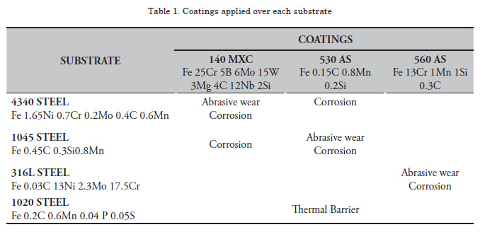
Table 1 summarizes the coatings applied over each substrate, their chemical composition, and the characterization studies performed. For wear and corrosion tests, 20x20x5-mm size samples were used, except for the 316L steel where samples were 20x20x2 mm in size. To study thermal properties, 23.8-mm diameter and 2-mm thickness samples were used. For these studies, the substrate surface was first prepared by using an abrasive wheel. The coatings were then immediately deposited to prevent oxidation of the sample surface. Subsequently, a 95Ni5Al base coating was deposited, providing adequate surface roughness to improve adhesion of the system.
Finally, the coatings were deposited by using the following parameters: primary air pressure at 50 psi, voltage at 29 V, current at 220 A and projection distance at 200 mm perpendicular to the sample surface. All coatings were applied by using a EuTronic Arc Spray 4 system.
Characterization
Thermal spray coatings were structurally studied by using X-ray diffraction (XRD) with Pro Panalytical X-pert equipment, operating at 45 kV and 40 mA. The measurement of thickness and qualitative porosity was carried out with a Leco convex lens optical microscope via cross-section metallography. The coatings were studied at the surface by using a scanning electron microscopy (SEM) FEI QUANTA 200 system, in a highvacuum environment at 30 kV. Chemical analysis was performed before and after electrochemical tests with the same SEM equipment in EDS mode at 20 kV.
Microhardness tests
A Knoop microhardness test was conducted over the three coatings, with a 50-g load; using a Leco M-400-G2 hardness tester. Measurements were made with a depth profile from the surface of the coating into the substrate.
Wear tests
Wear tests were performed using equipment meeting ASTM G65 standards, which determines abrasive wear by contact between dry sand and a rubber wheel against the sample material [8]. The sample weight loss is reported in units of volume (mm3). The test parameters were set at: 130 N load, time 1 min, sand flow at 300-400 g/min and 200 rpm of the wheel.
Electrochemical tests
Potentiodynamic tests were performed by using a GamryReference 600 Potentiostat/Galvanostat/ ZRA system with a high-purity graphite counterelectrode and a saturated calomel electrode (SCE) as reference, following ASTM G5 standard recommendations [9]. The area exposed to this solution was 0.79 cm2 within an electrolyte at 3% NaCl. The sweep was carried out between -0.3 and 1.0V with respect to the potential rest, at a scanning rate of 0.5 mV/s.
Study of Thermal Properties
The coatings were subjected to thermal treatments at 600, 800, and 1000ºC for 4hrs and at 1000ºC for 24hrs. Afterwards, electrochemical tests were performed by electrochemical impedance spectroscopy at room temperature, using a 0.01- M electrolyte (K3Fe(CN)6)/K4Fe(CN)•3H2O) [10]. Prior to the measurement, a 45-minute wait was established to allow for stabilization of the open circuit potential and to ensure the penetration of the electrolyte through the open pores. The area exposed to this solution was 0.79 cm2; electrochemical impedance spectroscopy measurements were performed with initial and final frequencies of 10 mHz and 100 kHz, respectively, with a 10-mV perturbation. Subsequently, the coatings were studied via SEM to observe the microstructural changes and XRD to determine the oxides formed.
Results And Discussion
Microstructure and Chemical Analysis
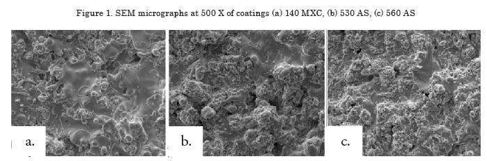
Figure 1 shows the micrographs of each of the surface coatings studied. In general, coating surfaces presented lenticular structures and splat formation, as expected for these coatings. Likewise, low roughness values were observed in the coatings, with low oxide content and porosity. Thereafter, roughness was measured with a diamond edge profilometer, obtaining roughness values of Ra = 5.1, 5.44 and 6.23 μm for 140 MXC, 530 AS, and 560 AS coatings, respectively. To measure thickness, cross sections were performed and samples were observed with an optical micrograph; 10 measurements were made to obtain the average thickness. In the micrographs, fewer pores and oxides were observed present in the 140 MXC coating than in the 530 AS and 560 AS coatings, agreeing with the manufacturer's specifications. The XRD spectra of 140 MXC nanocomposite are presented in Figure 8, but an A wire coating spectra was first registered, where only Fe was found; this suggests that the amorphous phase to form the nanocomposite is found in the powder, we also observed CrO2. Figure 10 shows XRD spectra for the 530 AS coating. This coating revealed the presence of Fe and FeO and Fe2O3 oxides, which are probably formed when the particles melt and react with the surrounding environment before depositing over the substrate and solidifying. In turn, on the 560 AS coating (Figure 12) it was noted that Fe3O4 oxide and Fe-Cr compounds were formed.
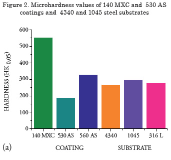
Measurement of microhardness
Results of the Knoop hardness test are shown in Figure 2. The highest hardness was observed in the nanocomposite, possibly due to the presence of hard tungsten-, niobium- and chromium-based elements [11]. An increase in hardness in the 560 AS coating was observed because of the presence of the martensite phase [12], while for the half-carbon coating, the lowest microhardness was observed because of the absence of alloying elements and the amount of oxides formed [13.14], which produces a coating not suitable for applications where the part will be subjected to wear, i.e., recommended for applications in cases of dimensional recovery.
Abrasive Wear Tests
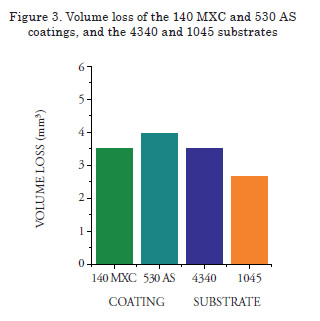
Volume loss values obtained are presented in Figure 3. In the case of the 560 AS coating, the abrasive wear test was not performed because sample thickness was not sufficient to be mounted on the sample-holder of the abrasive wear equipment. The 140 MXC coatings lost less volume during the test, agreeing with the highest hardness values. This may be possible due to the formation of a microstructure with good mechanical properties, based of an amorphous matrix composed of chromium, niobium, and molybdenum elements, and nanostructured structures without preferred orientation [13]. These measurements should be confirmed via transmission electron microscopy. After these tests, samples were analyzed via SEM, where signs of wear mechanisms and plastic deformation were observed. When the chemical composition was determined, silicon, oxygen and carbon traces were observed; the first due to the silicon sand introduced by the abrasive material of the experiment, and the other elements probably due to the interaction of the coating with the surrounding environment.
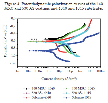
Potentiodynamic Polarization
Figure 4 shows the Tafel polarization curves of the 140 MXC and 530 AS coatings. To observe the effect of substrate resistance against corrosion, 140 MXC and 530 AS coatings were deposited onto two substrates (SAE 1045 and 4340 steel).
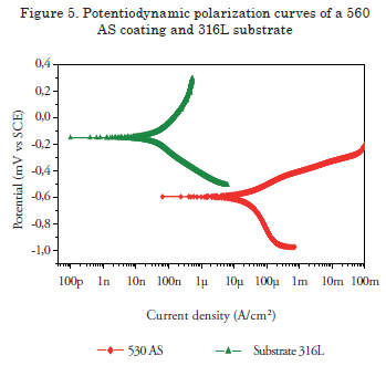
For these coatings, an improvement in the resistance corrosion for both substrates was observed, that is, the corrosion potential values are more positive and present lower corrosion resistance values. These observations are consistent with the chemical composition, given that the presence of niobium and chromium, even in small quantities, improves corrosion resistance [15]. The 530 AS coating was also deposited onto the two substrates. In this case, corrosion resistance showed improvement when applied over the 1045 substrate, but when applied over a SAE 4340 steel substrate, no improvement in the electrochemical behavior was observed; thus, manifesting the importance of substrate selection. Figure 5 shows the Potentiodynamic polarization curves of the 560 AS coating deposited over the 316L stainless steel. It was observed that the substrate had better corrosion resistance behavior without the coating, possibly due to the martensitic nature of the stainless coating while the substrate is totally austenitic. An insulating layer forms on the surface of a 316 austenitic stainless steel, which makes the steel passive; thereby improving corrosion resistance [16]. For this reason, this system is recommended for applications where corrosion and wear act synergistically.
Thermal barrier behavior
The micrographs in Figure 6 show the degradation of coatings due to heat treatment at 1000°C over 4 h [17], which is evident when compared to Figure 1. (see page 12).
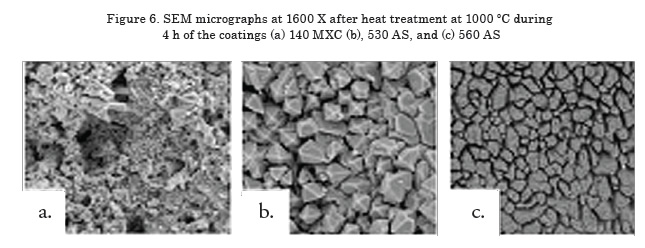
Figure 8 shows the Bode plot of the 140 MXC coating after heat treatment. A significant increase in the impedance modulus was observed in the samples under heat treatment when compared to the untreated coating. In turn, an increase in the impedance of the system was observed after isothermal oxidation, which can be related to thermal degradation after the onset of oxides. After a 4-h exposure at 800ºC, the results describe some variations; for example, overlapping the curve at 1000ºC during 24 h at low frequencies. Nonetheless, it was expected that under high temperature treatment over long periods of time, an increase in the concentration of oxides would be observed. However, this tendency was not observed. The XRD spectra in Figure 9 shows that at 800°C, there was the highest concentration of oxides, such as chromium oxide (Cr2O3) with rhombohedral crystal structure, manganese oxide (MnO) with a face-centered cubic structure, and molybdenum oxide (MoO3) with a monoclinic structure, which may act as a thermal barrier. Samples subjected to treatment at 1000°C for 4 and 24 h presented ferrous oxides, which are not recommended for insulation applications [18]. Figure 9 shows the Bode plot of the 530 AS coating, showing that impedance is significantly higher for heat treatment at 1000ºC for 24 h, which suggest a high rate of oxide formation [19]. The XRD spectra for the 530 AS coating (Figure 10) show the formation of Fe2O3 at room temperature [18]. Figure 11 shows a Bode plot of the 560 AS coating. Overlapping of the curves at lower frequency values is observed in more aggressive treatments. In turn, treatment at 800°C decreases impedance values drastically, suggesting oxide formation.
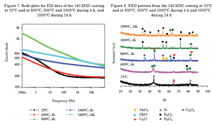
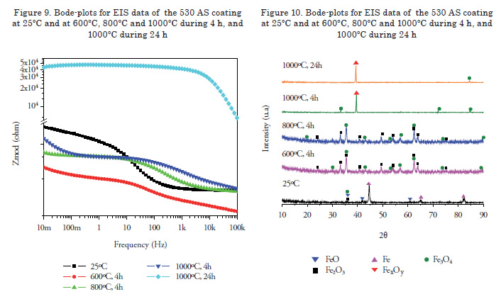
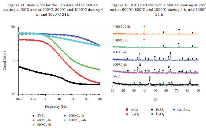
Figure 12 shows the XRD spectra of a 560 AS coating. No significant increase in the oxide phase formation is noted with increasing temperatures. However, the chromium phases, an essential element of this coating, are only observed in the coating without heat treatment [20]. For temperatures above 800ºC the presence of Fe2O3 oxide is well observed, and for treatments below this temperature Fe3O4 and Fe2O3 oxides were present [21].
Conclusions
In general, the coatings used in this work can improve resistance to corrosion and abrasive wear of carbon steel substrates; however, the efficiency of such protection depends largely on the defects of the microstructure of the coating, as well as the corrosive and wear environment. Moreover, the coatings studied are a viable alternative for applications in the ship building industry, and the coating should be chosen given the stress and conditions to which the piece will be subjected. The conclusions drawn from the microstructural characterization, the thermal evaluation, and resistance to corrosion and wear of the coatings produced are presented as follows.
With regards to the tests performed on trademark 140 MXC, 530 AS, and 560 AS coatings applied via electric arc thermal spraying technique on substrates used in the ship building industry; it was found that the coating with best performance, that is, the coating with the best combination of properties in terms of corrosion resistance, microhardness, abrasive wear resistance, and thermal barrier properties was 140 MXC, followed by 560 AS and, finally, 530 AS. The importance of the substrate for corrosion testing was determined, for it is important to use stainless steel materials which have a passivation layer that improves the electrochemical behavior of the system as a whole. Regarding the properties of the coatings as thermal insulators, more tests are required to determine the feasibility of nanocomposite 140 MXC coatings at temperatures below 800ºC. The 530 and 560 AS coatings were discarded for thermal applications.
References
1. LASHRERAS E., MARÍA J. (1978). "Tecnología del acero". Ediciones Cedel. Tercera edición, Barcelona. España.
2. GEDZEVICIUS I., VALIULIS A. (2006). "Analysis of wire arc spraying process variables on coatings properties". Journal of Materials Processing Technology.
3. Handbook of Hard Coatings. Tomo 3. Thermal Spraying and Detonation Gun Processes. (2003).
4. MARULANDA, J. (2000). "El Rociado Térmico y sus Aplicaciones". Publicación Universitaria.
5. DOBLER K. (2006). "Reconditioning Power Generation Components with Thermal Spray Welding Journal".
6. Department of the Army. U.S. Army Corps of Engineers. Thermal spraying: New construction and Maintenance. EM 1110-2- 3401. Washington, DC 20314-1000. (2005).
7. COOKE K., OLIVER G., BUCHANAN V., PALMER N. (2007). "Optimisation of the electric wire arc-spraying process for improved wear resistance of sugar mill roller shells". Surface & Coatings Technology 202 185–188.
8. ASTM Designation: G65. Standard Test Method for Measuring Abrasion Using the Dry Sand/Rubber Wheel Apparatus. (2001).
9. ASTM G5 – 94. Standard Reference Test Method for Making Potentiostatic and Potentiodynamic Anodic Polarization Measurements. (2004).
10. GARCÍA J., SALAZAR A., MÚNEZ C.J., UTRILLA V. y POZA P. (2005). “Análisis de la degradación de recubrimientos de barrera térmica por espectroscopía de impedancia electroquímica”. Revista Cerámica y Vidrio, 232-239.
11. GEORGIEVA, THORPE P., YANSKI R., SEAL A. (2006). “Nanocomposite materials: an innovative turnover for the wire arc spraying technology”. University of Central Florida, Mechanical, Materials and Aerospace Engineering Department.
12. KRAUSS G. (1989). "Heat Treatment and Processing Principles". Eds, ASM International.
13. SMITH W. (1993). "Structure and Properties of Engineering Alloys". Mc Graw Hill International Editions.
14. JANDIN G., LIAO H., FENG Z.Q., CODDET C. (2003). "Correlations between operating conditions, microstructure and mechanical properties of twin wire arc sprayed steel coatings". Materials Science and Engineering A349 298/305.
15. ZHOU Z., WANG L., WANG F., LIU Y. (2009). “Formation and corrosion behavior of Fe-based amorphous metallic coatings prepared by detonation gun spraying”. Transactions of Nonferrous Metals Society of China. S634-s638.
16. ASM Handbook, Volume 1, Properties and Selection: Irons, Steels, and High Performance Alloys. (2005).
17. ABEDINI A., POURMOUSA A., CHANDRA S., MOSTAGHIMI J. (2006). “Effect of substrate temperature on the properties of coatings and splats deposited by wire arc spraying”. Surface & Coatings Technology 201 3350–3358.
18. SONGA S.-H., XIAO P., WENG L.-Q. (2005). “Evaluation of microstructural evolution in thermal barrier coatings during thermal cycling using impedance spectroscopy”. Journal of the European Ceramic Society 1167–1173. 25.
19. CULHAA O., TOPARLIA M., SAHINB S., AKSOYA T.. (2008). "Characterization and determination of FexB layers mechanical properties”. Journal of Materials Processing Technology 206 231–240.
20. JIN G., XU B.S, WANG H. D, LI Q. F, WEI S.C. (2007). "Microstructure and tribological properties of stainless steel coatings sprayed by two methods based on spraying". Surface & Coatings Technology 201 5261–5263.
21. AMOKRANE M., BOUNARB N., BENABBASB A., ATIA A. (2008). “Study of microstructure, phases and microhardness of metallic coatings deposited by flame thermal spray”. Journal of Materials Processing Technology 200 410–415.