Passenger Submarine Concept Design for
Oil Production Offshore Systems
Diseño conceptual de submarinos de pasajeros para sistemas oceánicos de producción petrolera
Thiago Lobão de Almeida1
Victor Coracini Tonacio2
Abstract
The paper proposes an innovative solution to transport workers of offshore oil production platforms from the coast to their units, which operate at the Pre-Salt exploration, 300 km from the coast. A passenger submarine concept design was developed, justified by the range of practical obstacles observed in the current modes of transportation, helicopters and supply boats. Requirements like operational depth (100 m), passenger capacity (250 people), and cruising speed (minimum 13.4 knots) are defined, based on estimates. Firstly, it seeks the adoption of air-independent propulsion (AIP) systems, by fuel cells (PEMFC). However, the work progress leads to an entire electric propulsion system. The internal arrangement is elaborated, regarding passenger comfort, structural constraints, allocation of batteries and ballast tanks. Then, after a hydrodynamic hull optimization, by Computational Fluid Dynamics analysis, we provide a final configuration with 100-m length and 9.7-m diameter, operational speed of 16 kt, and autonomy of 26 hours.
Key words: Passenger submarine concept design; Manpower flow in offshore systems; CFD analysis.
Resumen
El documento propone una solución innovadora para el transporte de los trabajadores de las plataformas de producción de petróleo en alta mar a sus unidades, que operan en la exploración pre-sal, a 300 kilómetros de la costa. El proyecto conceptual de un submarino de pasajeros se desarrolló, justificado por la serie de obstáculos prácticos observados en los medios de transporte actuales, helicópteros y barcos de suministro. Requisitos como la profundidad operativa (100 m), la capacidad de pasajeros (250 personas) y la velocidad de crucero (un mínimo de 13,4 nudos) se definen, con base en estimaciones. Al comienzo, se propone la adopción de sistemas de propulsión independiente del aire (AIP), por las celdas de combustible (PEMFC). Sin embargo, la evolución del trabajo conduce a un sistema de propulsión eléctrica completa. La disposición interior es elaborada con respecto a la comodidad del pasajero, las limitaciones estructurales, la asignación de las baterías y tanques de lastre. Entonces, después de una optimización del casco hidrodinámico, mediante el análisis Computacional de Dinámica de Fluidos, se presenta una configuración final con 100 m de longitud y 9,7 m de diámetro, 16 kt como la velocidad de funcionamiento y una autonomía de 26 horas.
Palabras claves: Proyecto conceptual de un submarino de pasajeros; Flujo de mano de obra en sistemas en alta mar; Análisis CFD.
Date received: November 28th, 2010 - Fecha de recepción: 28 de noviembre de 2010
Date Accepted: December 15th, 2010 - Fecha de aceptación: 15 de diciembre de 2010
________________________
1Universidade de São Paulo. Brazil. e-mail: thiago.lobao@poli.usp.br
2Universidade de São Paulo. Brazil. e-mail: vtonacio@usp.br
............................................................................................................................................................
Introduction
Within the current Brazilian context, a unique opportunity has been noted: increased oil production since the discovery of petroleum reserves in the pre-salt area, demanding a greater flow of human resources between the coast and the offshore units.
Current Solutions
Currently, two alternatives exist, supply boats and helicopters. These possibilities, however, face a series of setbacks. For helicopters, the problems include low passenger capacity per vehicle, high variable cost, dangers of landing on platforms, and infeasibility under adverse weather conditions. For boats, the main obstacles are high discomfort, poor transition systems, risk of collisions, and climatic constraints.
Alternative Proposal
To avoid wave influences,which cause uncomfortable journeys, the possibility of adopting an underwater mode of transport, a submarine, was pondered. A range of submerged transition alternative proposals are being developed to solve the boarding issues.
The main approach consists of a trail to conduct the vehicle untilthe Floating Production Storage Offload (FPSO) platform, dispensing the need toconstruct submerged complex systems like elevator cylinders.
Methodology
The spiral design for submarines waspresented by Jackson (1992). Before dimensional estimates, the analysis focuses on the conditions of null buoyancy. The spiral begins with the verification of the balance between submerged displacement, weight, and ballast. Then, the work proceeds to dimensional estimates. The definition of hull form permits estimating water resistance at a proposed speed. The analysis of a series of helices enables hull-propeller-motor interaction. Hence, the nominal engine power required is obtained. With the propulsion subsystems estimated, the internal arrangement of the hull is elaborated, analyzed in terms of weight distribution and structural aspects.
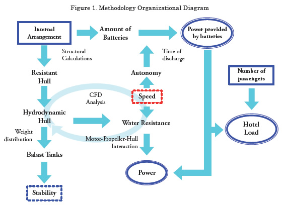
In this project, however, in which the strictly military modules are discarded and new modules for passenger accommodation have to be developed, there is no way to rely on the initial estimates of weights presented in the literature. This fact implies the creation of an alternative approach, represented by Figure 1. The new sequence of activities begins with the proposal of the internal arrangement, the leading element related to people transportation.
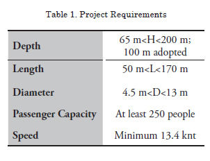
Project Requirements
The estimates related to project requirements are supported by the theory of hydrodynamics and practical context data, always following guidelines according to Brazil’s current oil exploration policies. The proposals assumed to achieve the final results herein exposed are specified in detail in Tonacio & Almeida (2010).
First Spiral Design
The First Spiral Design, whose details can also be thoroughly checked in Tonacio & Almeida (2010), begins with the definition of available space for passengers along the resistant body. This first conscious calculation of the necessary area enables comparing other existent submarine hulls, seeking to select the most proper case that facilitates achieving numerical estimates (submerged volume, displacement, water resistance, and power). In this case, the Type 212 German Series stood out as the most helpful reference. Primarily, the intention of an exclusive AIP propulsion system was analyzed, looking for advantages and negative points among the different options described in the academic literature. The Polymeric Fuel Cell (PEMFC) system was recognized as the greatest opportunity for future submarine designs. Thus, a first propulsion plant using this sort of energy source (Adams, 1990) was idealized. However, the design weight distribution was compromised due to the lightweight characteristics of the PEMFC, requiring an excessive ballast cargo. In essence, the results lead to the implementation of a refining second spiral design.
Second Spiral Design
Introduction
The project’s second phase sought two main objectives: to provide more comfortable and harmonious environments to passengers and to compensate for the huge and light volume destined for passengers by using a heavier propulsion alternative.
New Propulsion System
As already cited, the light PEMFC propulsion option has to be replaced by another heavier alternative, so we now propose an electric propulsion system, powered exclusively by batteries.
The search for a new engine, which keeps the innovative character sought by this project, points to a new electric motor technology, High- Temperature Superconductor (HTS). This new motor model has been destined for the marine industry and provides a weight and volume reduction of nearly 70% and 50%, respectively, in comparison with traditional electric motors.
Currently, two HTS motor configurations are being commercialized, i.e., 5MW and 36.5MW motors. Considering the power resulting from the past spiral design, the first option is close to the project’s necessity and can allow higher operationspeed, depending on the amount of batteries allocated. Therefore, the adoption of the HTS motor (5MW), with 23 tons and 2.5m x 1.9m x 1.9m (DxWxH) is perfectly suitable.
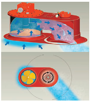
According to the necessity for precise maneuverability,two 360°bow thrusters installed at the bottom of the hull (one in front and another in the back) were adopted to give the submarinemore mobility, especially at the moment of the Submarine-Platform coupling. The following illustration shows the principle of operation of the Veth-Steering Grid, the most suitable model for this objective.
Figure 2. Bow thruster´s principle of operation
The choice of batteries mustconsider energy, access, volume, and weight aspects. The first model of energy source foundincluded lead batteries manufactured by Sepang, traditionally used in submarines. They are heavy (395 Kg), allow for top access and have an elongated format (29x30x150cm - LxWxH); thus, they are appropriate for allocation at the bottom of the PMB hull.
In certain places of this submarine, top access is not advantageous. Therefore, we looked for batteries with side access, which allow stacking. We found a new generation of lithium ion batteries (manufactured by Onyx), which are much lighter than the lead ones and carry more energy. Their format is more advantageous for the engine room. Nevertheless, it is not possible to replace lead batteries in all cases, because a lot of weight would be lost, which is not interesting for the submarine.
New Internal Arrangement
The new scheme for the internal arrangement is presented in Figure 3. It portrays the main modules, which will be presented in the subsequent sub-items.To start, it is important to highlight that a volume throughout the hull was reserved for the ballast tanks, which may be completely used or not, depending on the calculations in item 5.6 (Ballast Allocation). The Rhinocerossoftware was used in the 3D modeling, which provides the images in the next sub-items.
Accommodations and Refectories (Parallel Medium Body - PMB)
Given that one of the targets of this second phase is to increasepassenger comfort, the cabins were enlarged and spaced from each other. The booths now have dimensions of 210cm x 90cm x 135cm (LxWxH). The image in Figure 4 shows the new configuration.
The top of the corridor is wider than the past configuration to make the environment more harmonious, besides of bringing up a step that enablesaccess to the upper cabins. At first impression, it seems a waste of space, but it creates a runner for air ventilation, or ducts for electric cables, for instance. Thenarrowest part of the corridor has 60cm, on upper deck, and 80cm, on lower deck. Four refectories (Figure 5) were projected to make the passenger meals more comfortable and sociable. Next to them, 12 toilets in total were projected. The dimensions of the new accommodations arrangement require a 9-m fixed internal diameter, for the PMB cylinder, one of the inputs for the structural calculation.
Figure 3. Scheme of the new arrangement
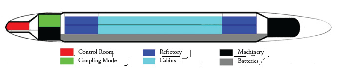
Figure 4. Inside cabins
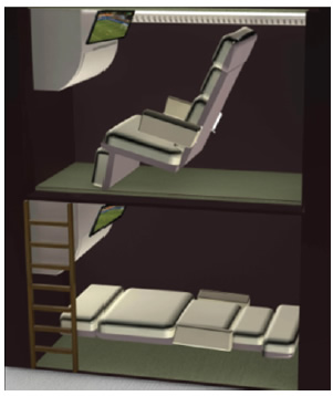
Figure 5. Refectories
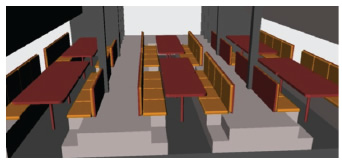
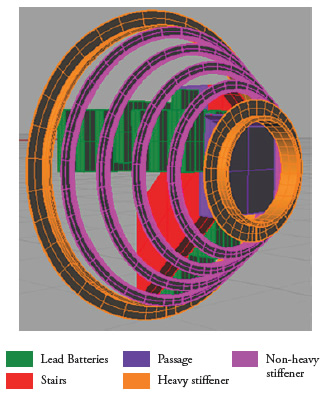
Figure 6. Cross Section of structure
Batteries (PMB)
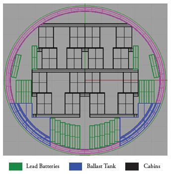
Most of the batteries were allocated in the bottom of the PMB hull, under the lower accommodation deck. This area is completely isolated from the passenger area, but there is a corridor in the middle of battery area that permits crew access. On both sides of the hull, there are also a few batteriesthat, like the others, are isolated from the passengers and accessible for the crew. The chemical reactions occurring inside the batteries release gases, which in large amounts are harmful to humans; thus, this area also allows implementing an exhaust system to solve this problem. Figure 6 shows battery arrangement in the PMB cross section.
Engine Room (M)
At the stern, a cylinder with 5.8m of internal diameter is projected to lodge the HTS motor, the reducer, and a considerable amount of batteries (Figure 7). In this case, batteries with side access are more advantageous than those with top access. Each of the“bow” thrusters can be accessed through this room.
Coupling Section (C)
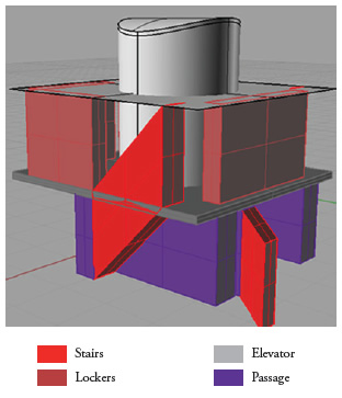
The elevator access to transport passengers to the FPSO and vice versa will be allocated in this section, at the stern of the vessel (Figure 8). There are also some lockers for people to leave their luggage.
Figure 7. Engine Room
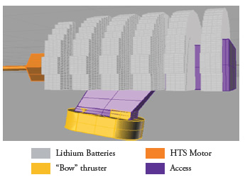
The lower deck is destined for a small engine room, with some lead batteries and the front bow thruster. This cylinder has an8-m internal diameter.
Figure 8. Coupling Module
Control Room (CR)
A small, 3-m internal diameter cylinder was destined to centralize the control of the vessel at the bow extreme.
Transitions between Cylinders
The four cylinders, which are components of the resistant hull, are connected by conical transitions.
Figure 9. CR-C Transition
Their internal diameters mustmatch the cylinders’ diameters and their lengths are determined, considering the space necessary for the stairs, which allow passage of security crew (Figure 9).
Structure
The project’s scope, a passenger submarine, is determinant in the step sequence of the spiral design. Because there are no estimates or references for passenger submarines, the starting point of this project’s spiral is the internal arrangement. The internal configuration described in the last subitem will be the input for the structural calculation of the resistant hull.
Table 2 lists the internal diameter and the minimum length required by the new internal arrangement for each of the sections.

The shell and the non-heavy-stiffenerswill be built outside this fixed internal diameter. The heavy stiffeners sometimes enter into this space, but these occasions were carefully planned so that the internal arrangement is not compromised and the free circulation inside the vessel is maintained.
The collapse pressure is another input for structure calculations. The hydrostatic pressure the submarine’s structure would not resist was defined as the double of the operational pressure, which, in the practical context, is not exceeded. The hydrostatic pressure at 110-mdepth1 is 1.1 MPa, so the collapse pressure determined is 2.2 MPa. For the selection of materials, a search of the history of submarines reveals that HY-80 steel is most commonly used, so its properties are adopted in this project: Yield strength (552 MPa), Poisson’s ratio (0.3), and Modulus of Elasticity (205000MPa).
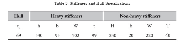
The 6th section of the ABS (American Bureau of Shipping, 2010) rules for underwater vehicles substantiates the structure calculation. Shell thickness, the space between stiffeners and the parameters of their cross section (T) (Figure 10) were calculated (Table 3), based on the following criteria: inter-stiffener strength, overall buckling strength, stiffener stress limits, tripping and local buckling, and inertial requirements. The group of stiffeners indicates the design of the resistant hullformat (Figure 11).
Figure 10. Stiffener Cross Section
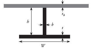
Figure 11. Resistant Hull
Hydrodynamic Hull Optimization
After the resistant hull is conformed, based on the structural calculations, the dimensional restrictions are determined for hydrodynamic hull optimization because, obviously, the hydrodynamic shell cannot cross inside the resistant hull.
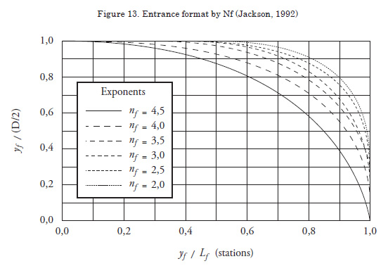
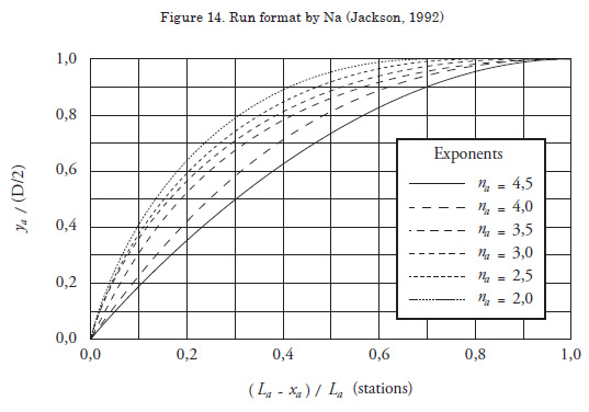
In Jackson (1992), a study for submarine hull proposes an ideal format for good hydrodynamic performance (Figure 12). This format consists of three parts: entrance (bow), PMB, and the run (stern) (Figure 13). The PMB is a cylinder; the entrance can be calculated as an ellipsoid of revolution, and the run as a paraboloid of revolution (Figure 14). The upcoming equations and graphics refer to the bow and stern formats.
Figure 12. Hull format by Jackson (1992)
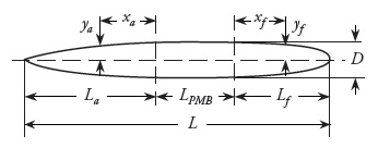
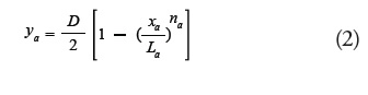
Equation for the bow format (ellipsoidal):
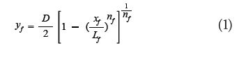
Equation for the run format (paraboloid):
In function of the parameters presented, La, Lf, na, nf, the hull was modeled by using the Friendship® software. Friendship® provides the offset file, with the hull’s quotas, and the command file and triggers Shipflow® for CFD analysis. The main analysis was made by XCHAP, more efficient and reliable when used with low input values for Reynolds coefficient. Therefore, the different hull cases under analysis were modeled in 1:20 scale (instead of Re~108, authors adopted so Re~105 for simulation). In the traditional formulation of the water resistance estimate (the following equation), the total resistant coefficient (Ct) can be split up in three components: Cf (Frictional Coefficient), Cw (Wave Generation Coefficient) and Cpv (Viscous Pressure Coefficient, which concerns the geometry of the hull, regarding the vortices generation), the most important coefficient in this analysis.
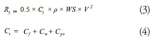
The other parameter directly influenced by hull geometry variables is WS (wetted surface). Therefore, minimizing the product WSxCpv reveals as the main strategy to find the optimum hydrodynamically hull case. Actually, this number is not going to be used for the water resistance calculation, it is only a comparative value, a qualitative indicator.
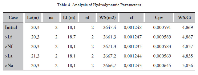
The optimization of the hull was not automatically made. An initial configuration with the smallest WS was analyzed, from which the parameters were increased in order to improve the viscous pressure parcel. The observation of the product (WSxCpv) behavior enables the perception of which kind of geometric improvement compensates the WS increasing. As shown on the following table, the increases of the bow’s length (Lf) and the stern‘s curvature (Na) don’t optimize the hull performance. On the other hand, the parameters La and Nf, whose increases improve the performance, are going to be analyzed separately (Table 4).
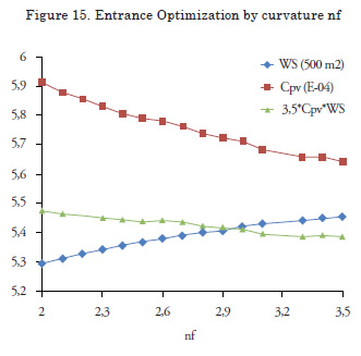
To understand the bow’s curvature effects, several values for Nf were tested, between 2 (the space restriction) and 3.5 (the maximum curvature analyzed by the Friendship®, from which the software doesnot run for mesh conditions). The values of the other parameters are equal to the initial configuration (Figure 15).
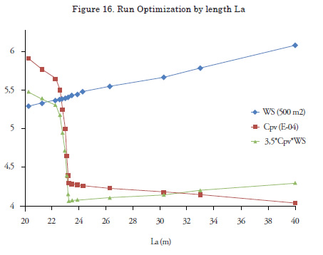
The same analysis is made for the parameter La. Thereis an optimum value that improves the geometry decreasing the Cpv, from which the more elongated stern effects donot overcome the WS increase (Figure 16).
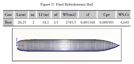
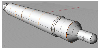
The best stern and the best bow obtained by the individual analyses are combined, culminating in the best hull geometric configuration, as expected (Figure 17).
Speed and Power
The definition of the operational speed is an iterative method because the speed determines at the same time the autonomy required, which influences battery productivity and water resistance, which is the main factor of the motor power (SHP). These two paths have to converge, respecting the amount of batteries allocated (Table 5) and the Hotel load (the power required by the crew and the auxiliary systems), estimated as 750 Kw.

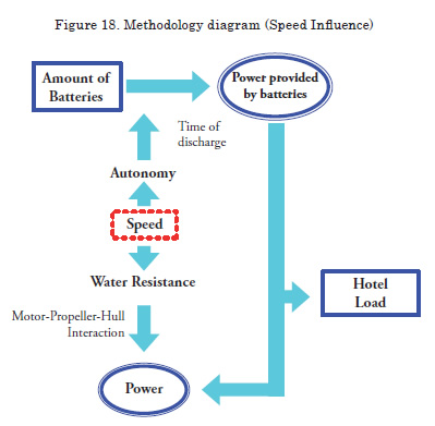
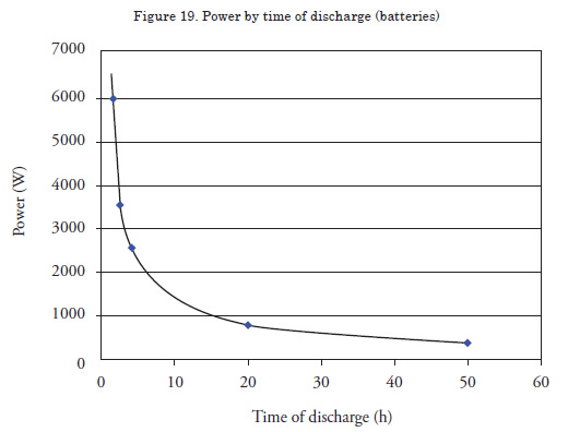
Figure 18 is a diagram of the total methodology presented in the beginning of this paper, which illustrates this moment of the project. The minimum speed required, 13.4kt, is the starting point of this cycle. Then, the speed is gradually increased to obtain the maximum speed possible, respecting the constraints.The autonomy for the respective speed is the time of battery discharge, which determines the power provided. The graphic in Figure 19 shows the power behavior of the lead battery adopted in this project.
Water Resistant
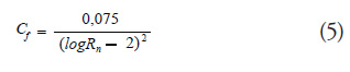
The water resistance estimate is made according to the traditional method. Because of the specificity of the submarine’s design, the Ctcoefficient was calculated according to the theory described by Jackson (1992). Ct is the sum of five components: Cf, δCf, Cr, CA, CS.Cf is the friction coefficient, calculated by the formula that was agreed upon at the International Towing Tank Conference:
The parcel δCf is sometimes called roughness coefficient or the correlation allowance, related to fabrication uncertainties; Arenzel and Mandel (1960) suggest 0.0004.Cr, developed from Bernoulli’s conservation of energy theorem, accounts for the pressure difference along the hull;it is similar to Cpv
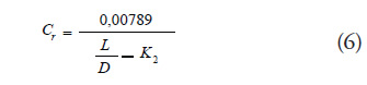
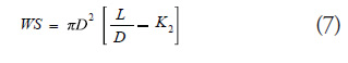
K2 is extracted from the following equation:
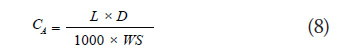
CS refers to the resistance of the sail, which is absent in this submarine’s design. CA is the drag coefficient of the appendages. The first approximation is adapted from Jackson’s suggestion as:
Motor-Propeller-Hull Interaction
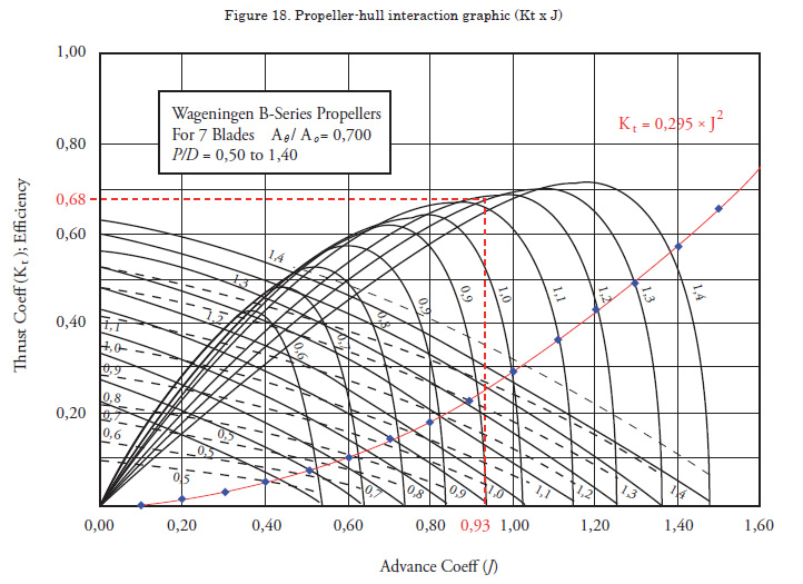
The propeller presented by Jackson (1992) with 7 blades is very often used in submarines, so for this concept design it is going to be adopted. For the definition of the propeller’s diameter, we used the ratio of 60% of the hull diameter; therefore, Dp=5.81m.
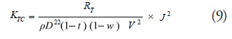
The wake and thrust coefficients(w and t, respectively) are extracted from the graphic data provided by Jackson (1992).The hull and the propeller can be combined by the relation of the thrust coefficient (Kt) provided by the propeller data (Figure 20) and provided by the following equation:
The interception between this parabola just presented and the propeller Ktcurves, for each P/D relation, provides the open water efficiency ![]() and the advance coefficient (J).
and the advance coefficient (J).
The other efficiencies included on power calculation are ![]() , the relative rotative efficiency, and
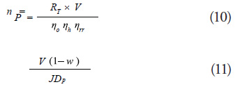
, the relative rotative efficiency, and ![]() =(1-t)/ (1-w), the hull efficiency. Therefore, the motor power required and the rotation are presented, respectively:
=(1-t)/ (1-w), the hull efficiency. Therefore, the motor power required and the rotation are presented, respectively:
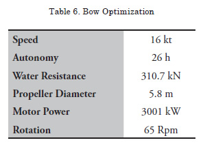
The iterative method converges to a speed of 16 kt. The principal results are demonstrated in Table 6:
Weight distribution and Ballast Allocation
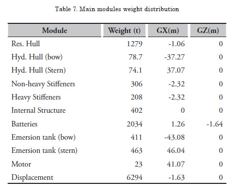
The most significant weights were calculated with high precision, as well as their centroids.
The two volumes between the hydrodynamic hull and the resistant hull, located in the bow and in the stern, are floodable, once the hydrodynamic hull cannot resist the water pressure. However, in emergency cases, when the emersion is needed, high-pressure gas isadded to these volumes, pushing the water off. They are called emersion tanks and, as they are always filled, are considered weight. Weight distribution is resumed in Table 7. The centroids are referred from the middle of the PMB.
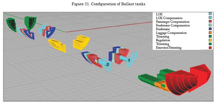
The other modules were estimated, remaining at 840t of fixed ballast. First, the main variable weights (passengers, luggage, oxygen storage in LOX tanks, fresh water) were identified, as well as their centroids, which were assumed as the same for their respective compensation tanks, in order to not cause trim. Actually, it can be noticed that these variable cargo are, comparatively with the submarine main weights, almost negligible.
For extreme load conditions, like heavy concentration of passengers frontwards or backwards, or even the emergency emersion situation, the use of trimming and regulation tanksto balance the submarine is necessary. Ballast allocation is illustrated in Figure 21.
Conclusions
After this second spiral phase, the final hull presents a total length of 100m, diameter of 9.7m, displacement of 6.294 tons, values included in the range of existingsubmarine hull dimensions. Good speed and autonomy conditions, moreover, reinforce the viability intentions of the designers.
Optimizations, however, are suggested, mainly expecting to reduce fixed ballast and overall structural weight. Perhaps good initiatives can be provided by re-evaluating the operation depth or even analyzing the possibility of adopting airplane configurations for people allocation, yielding more speed with less power installed.
Bibliography
ABS (American Bureau of Shipping). Rules for building and classing underwater vehicles, systems and hyberbaric facilities. 2010.
ADAMS, V. W. Possible fuel cell applications for ships and submarines. Journal of Power Resources. 1990. Vol 29. PP. 181-192.
GABLER, U. Submarine Design. 1ª ed. São Paulo. AMRJ/ETCN. 1991.
JACKSON, H. A. Fundamentals of Submarine Concept Design. SNAME Transactions. 1992. Vol 100. pp. 419-448.
NEWMAN, J. N. Marine Hydrodynamics. The Massachusetts Institute of Technology. 1977.
PRINS, C. A., EVERARD B., Approaches to submarine design in a changing environment. INEC. 1996. Paper 3.
1Depth considering the diameter, almost 10m, under the 100-mdepth