Ship Science and Technology (Cartagena) - Vol. 19 - n.° 37 - (155-165) July 2025 - www.shipjournal.co
DOI: https://doi.org/10.25043/19098642.269
Meysam Masoumpour 1
Hassan Ghassemi 2
Hossein Mousavizadegan 3
Guanghua He 4
1 Department of Maritime Engineering, Amirkabir University of Technology, Tehran, Iran.
2 Int. School of Ocean Science and Engineering, Harbin Institute ofTechnology, Weihai, China and Department of Maritime Engineering, Amirkabir University of Technology, Tehran, Iran Email: gasemi@aut.ac.ir ORCID: https://orcid.org/0000-0002-6201-346X
3 Department of Maritime Engineering, Amirkabir University of Technology, Tehran, Iran.
4 Int. School of Ocean Science and Engineering, Harbin Institute ofTechnology, Weihai, China
Date Received: October 29th, 2024
Date Accepted: November 15th, 2024
Publication Date: December 17th, 2025
The rim-driven propeller (RDP) is an attractive propulsion system for ship designers across various maritime applications. In this study, the Reynolds-Averaged Navier-Stokes (RANS) equations were employed, using the moving reference frame (MRF) method and steady-state numerical simulations to address applicability challenges. The study also incorporated the SST k - ω turbulence model. Initially, a Ka-Series (Ka4-0.70) +19A ducted propeller (DP) was selected, and the numerical results for hydrodynamic characteristics showed good agreement with experimental data. The study subsequently focused on the RDP, which, while utilizing the same propeller, features a distinct duct design due to its rim-driven configuration. The hydrodynamic characteristics of the RDP were obtained and compared with those of the DP. The results revealed that the RDP exhibits lower efficiency than the DP, primarily due to the gap and the presence of the rotor in RDP.
Key words: Shaftless propeller, Hydrodynamic characteristics, Rim-driven propeller, Ka4-0.70, Duct 19A.
How to cite this article
To cite this article, use the following format:
IEEE Format
[1] M. Masoumpour, H. Ghassemi, H. Mousavizadegan and G. He, "Numerical analysis of hydrodynamic characteristics of a shaftless rim-driven propeller" Ship Science and Technology (Cartagena), vol. 19, no. 37, pp. 155-165, 2025. DOI: https://doi.org/10.25043/19098642.269
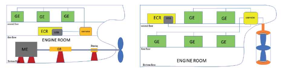
In a traditional propulsion system, the main engine (ME), generally the largest compartment in the vessel, drives the propulsion system, along with its associated shafting. The ME is located inside the hull of the ship, and the propeller is attached to a shaft that extends from the back of the vessel. The shaft is supported and its radial motion is restricted by bearings. To transform the high speed but low torque of the ME into the low speed and high torque needed to drive the propeller, a reduction gearbox (GB) is frequently used on some vessels. However, the shaft, bearings, and gearbox (GB) not only use significant engine room (ER) space and increase construction costs, but also generate loud noise and vibrations during operation, while significantly increasing frictional power loss. In contrast, the RDP represents a novel propulsion system that eliminates the need for traditional shafts, GBs, and other associated components. It instead employs a compact and integrated structure featuring high motor power density. ER arrangements of a marine vessel with a traditional propulsion system and an RDP are shown in Figs. 1(a) and 1(b), respectively. In this innovative system, the electric motor's stator is mounted within the duct, directly integrating the propeller and motor. The permanent magnet (PM) rotor creates a ring around the propeller rim. Several generator engines (GEs) as well as a convertor take the role of the ME. This configuration improves onboard comfort and allows more flexible equipment arrangement. The ship will have far greater mobility. Additionally, engineers can adjust the number of GE connected to the power grid based on real navigation needs to maintain higher energy. The maritime industry has increasingly focused on electrification and the development of hybrid vessels, positioning the RDP is an innovative type of combined motor-propulsor.
Fig. 1. The layout of the ship power transmission (a) Equipped with a traditional propulsion (b) Equipped with an RDP.
The RDP an innovative type of combined motor propulsor commonly known as a shaftless propeller, fundamentally changes traditional propulsion by connecting the driving engine to a shroud encircling the propeller. Instead of being driven by a shaft like traditional propellers, the RDP utilizes a circular rim connected to the blade tips to generate torque. The motor stator is positioned within the surrounding duct or nozzle, while the PM rotor is housed within the duct itself, as shown in Fig. 2(a). This integrated design, where the stator and rotor are separated by a seawater-filled gap for cooling and do not require waterproofing during rotation (see Fig. 2(b)) for internal configuration), offers significant advantages. It optimizes hull space utilization, resulting in a more spacious ER and enabling flexible equipment arrangement, thereby making the ship more versatile [1].
Fig. 2.(a) Integrated design mechanism (b) Internal arrangement for RDP.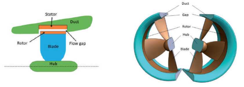
The RDP is most comparable to the DP in terms of construction and operation, as the propeller blades are mounted on a rotating rotor within a duct-shaped structure.
However, unlike the DP, which relies on a shaft system for propulsion, the RDP operates without one. In contrast to DP, RDP do not have tip clearance; instead, the duct and rotor surfaces create a gap for fluid flow. Both RDP and DP exhibit similar hydrodynamic characteristics, resulting in high efficiency and low noise propulsion [2, 3, 4]. A DP with Kaplan propeller and 19A duct was numerically analyzed under different conditions and oblique flows. [5, 6]. Some researchers access the DP experimental findings to confirm the accuracy of the numerical simulations because ofthe structural similarities between DP and the RDP [7]. A notable advantage of RDPs is their independence from the wake effects generated by the fairwater and rudder, resulting in uniform inflow and lower noise levels [8]. The RDP due to installed in vertical or horizontal through-body tunnels at both the front and rear of the vehicle, enhancing maneuverability [9]. Furthermore, it is vital to synchronize the hydrodynamic characteristics of the RDPs with relevant parameters to achieve optimal efficiency. Factors influencing hydrodynamic efficiency include the propeller's structural design, gap thickness [10], bollard pull condition [11] duct size and shape, and more [12]. Numerous studies have explored various aspects of RDP design and performance [13, 14, 15]. These investigations are often undertaken using physical experiments, numerical simulations, and combined methods [16, 17]. A ring thruster propulsion system was experimentally conducted to determine relevant hydrodynamic performance [18]. RDPs offer significant hydrodynamic and structural advantages compared to traditional propellers. However, as a relatively new propulsion technology, they still present challenges in design and performance analysis that require further research.
In recent years, the Reynolds-Averaged Navier-Stokes (RANS) equations have been employed to compute the hydrodynamic characteristics of RDPs. However, current research remains focused on a limited subset of potential geometries and operating conditions. Despite this limitation, numerical simulations serve as a valuable, low-cost tool for iterative design optimization. Specific investigations include the numerical analysis of vortex effects on the blade tip [19, 20] and the impact of key parameters such as duct aspect ratio, diffusion ratio, contraction ratio, and blade tip diameter ratio on RDP hydrodynamic efficiency [21]. Comparative studies at low advance coefficients indicate that the Shear Stress Transport (SST) k - ω turbulence model within the RANS framework outperforms the RNG k -ε model for capturing RDP-stator interactions [22, 23], leading to its widespread adoption in RDP numerical studies [24, 25, 26]. The Multiple Reference Frame (MRF) approach, a steady-state method for simulating rotating domains, is commonly utilized. Looking forward, methodologies include analyzing three uniform-diameter RDPs with different blade numbers via RANS solvers and an initial blade design [27], Comprehensive design systems for DPs, incorporating all necessary components, have also been formalized using block diagrams [28, 29, 30].
Numerous research articles have focused on RDPs, particularly regarding electric motors, control technologies, and hydrodynamic characteristics. These studies provide valuable references for the design and numerical analysis of RDPs. It is crucial to revise propeller design recommendations since blade loading in RDPs differs from traditional propellers, and the rim alters flow interactions. Consequently, challenges in the hydrodynamic design and characteristics analysis of RDPs remain. This study advances RDP research by systematically comparing the hydrodynamic characteristics of a traditional propeller DP and an RDP, using identical Ka4-0.70 propeller blades and a modified duct 19A.
In this article, numerical simulation was carried out on the hydrodynamic characteristics ofthe RDP, focusing on the adjustment, modification, and distribution modeling of the Ka-Series blades and duct 19A. The numerical results for the DP were compared experimental data, and showed in good agreement. The RDP is a novel development and rotor is driven by the permanent magnetic motor. So, the rotor is connected to the inside of the duct as a compact operation without mechanical transmission loss, no tip vortex and reduce noise and vibration. Present study carried out the hydrodynamic characteristics of the DP and RDP, which the rim driven effect on the duct and blade tip investigated. The rest of this paper is arranged in the following way: Section 2 described the governing equations and hydrodynamic characteristics.
Section 3 presented numerical implementation and validation for the DP. The hydrodynamic characteristics for the RDP, is presented and discussed in Section 4. Finally, the conclusion is given in Section 5.
In this study, the CFD solution is derived from the fundamental governing equations of hydrodynamic characteristics, which consist ofthe continuity equation and the momentum conservation equations. The Ansys CFX software was utilized as the solver to compute these equations, as illustrated below;
Continuity equation
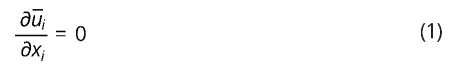
Momentum equation
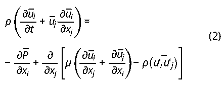
Where t is the flow time, i, j = 1, 2, 3 are the velocity components, ρ is the water density, p is the pressure, and μ is the dynamic viscosity of water. p(u'i-u'j) represents the Reynolds stress. These equations are solved using CFD software. The pressure diffusion term was solved using a second-order central difference scheme, the convective term is solved using a second-order upwind scheme, and the velocity-pressure decoupling was carried out using the coupled algorithm with the standard turbulence model.
In the present work, the open-water hydrodynamic characteristics were evaluated using the realizable SST k - ω turbulence model, which calculates the characteristics by solving these equations within the solution domain, incorporating pressure and shear stress to determine the propeller's hydrodynamic characteristics coefficients. These equations were solved along with Eqs. (1) and (2). The MRF approach was validated against DP experimental data and balances computational cost with steady-state accuracy for rotating systems. The hydrodynamic coefficients employed include the advance coefficient, thrust coefficient, torque coefficient and openwater propeller efficiency. These coefficients are defined as follows:
Advance coefficient

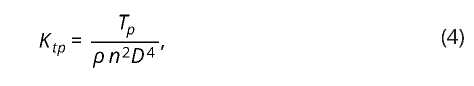
Thrust coefficient of propeller
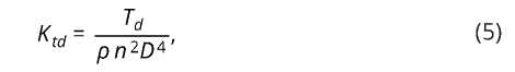
Thrust coefficient of duct
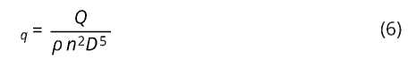
Torque coefficient of propeller
Open-water propeller efficiency
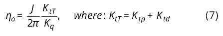
where Va is the advance velocity in m/s, n is the rotational velocity of the propeller in RPS is the fluid density in kg/m3 , D is the diameter of the propeller in m, and J is the advance coefficient, Ktp , Tp, Ktd, Td, Kq, Q, and are thrust coefficient of the propeller, thrust propeller η, thrust coefficient of duct, thrust duct, torque coefficient, torque, and open-water propeller efficiency, respectively.
This section discusses the division of the calculation domain and grid for both the DP and RDP simulations under open-water conditions. Due to the lack of specialized experimental data for RDP, it is essential to validate the RDP simulation thoroughly. To ensure the accuracy and reliability of the CFD methodology, this study first conducted a hydrodynamic characteristics analysis of the DP model 19A + Ka4-0.70, using experimental data as a benchmark.
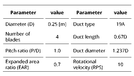
There is adequate experimental data to support the design and testing provided [31] in DP 19A + Ka. Comparing the simulation results of the DP with the experimental data enables validation of the CFD calculation approach for the RDP, as the flow fields of the two propellers are similar. The general model of the Ka4-0.70 DP is shown in Fig. 3. The detailed specifications of the Ka4-0.70 propeller are presented in Table 1. The gap between the propeller blade tip and the inner wall of the duct is 1.0 mm.
Fig. 3. Three-dimensional model of the DP.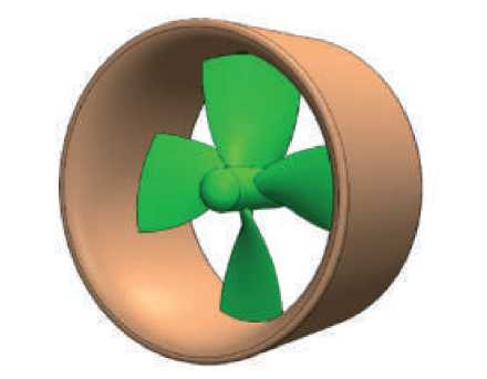
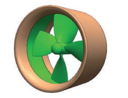
The structural layout of the RDP is similar to that of the DP, with the Ka4-0.70 DP design employed in this investigation. Table 2. presents some of its key characteristics, while Fig. 4 illustrates a 3D depiction of the RDP. The primary distinction between the DP and RDP lies in the presence of a rotor surrounding the blade in the RDP.
Table 2. Geometrical details of the RDP.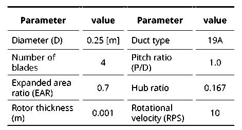
In this section, the hydrodynamic characteristics of the propellers for the DP and RDP are presented and compared, with a focus on their behavior under open-water conditions. For all the calculations involving varying advance coefficient, the rotational velocity of the propeller is maintained at a constant of 10 RPS while the inlet velocity is adjusted accordingly. The Cartesian coordinate system is used, where X, Y, and Z represent the downstream, upward, and starboard directions, respectively. The origin of the coordinate system is positioned at the center of the propeller hub. This study uses CFD simulations to analyze the thrust coefficient, torque coefficient, and efficiency of RDPs with varying advance coefficients. The calculation results for the seven operating conditions are presented in Fig. 5. The red curves depict the openwater hydrodynamic characteristics of the RDP, while the green curves represent the corresponding characteristics of the DP.
Fig. 5. Comparison of hydrodynamic characteristics between the RDP and DP.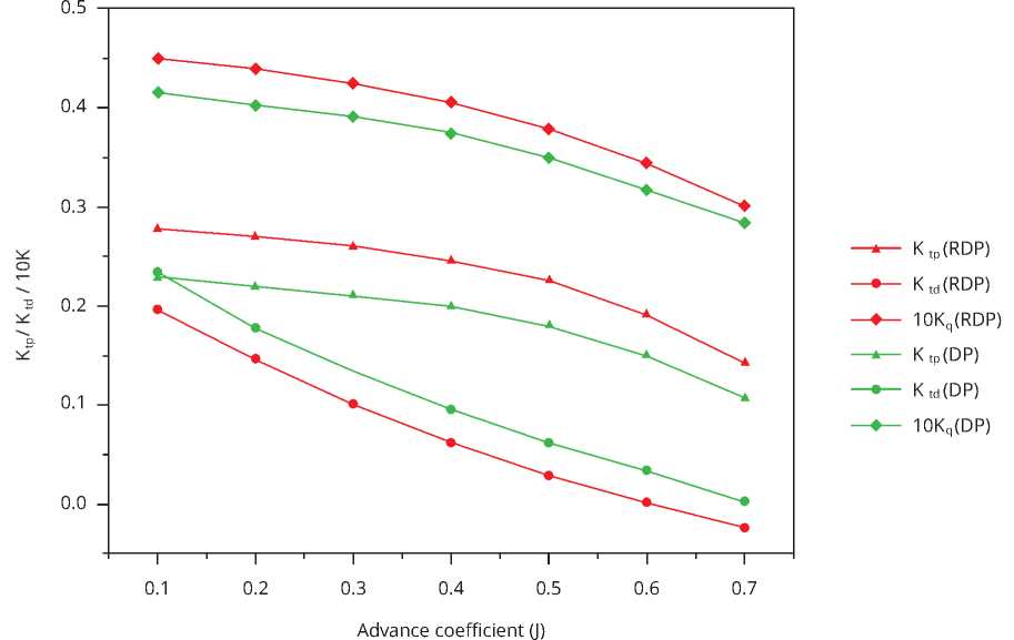
The thrust coefficient of the RDP system is significantly higher than that of the DP system, where the impeller generates the primary thrust coefficient of the propulsor, as shown in Fig. 5. Additionally, the thrust coefficients of both the DP and RDP systems show a strong linear relationship with the advance coefficient. For advance coefficients above 0.5, the DP thrust coefficient becomes negative, indicating resistance. Additionally, as shown in Fig. 5 the curves indicate that as advance coefficient increases, the torque coefficient, thrust coefficients, RDP and DP system exhibit a negative trend. Moreover, the torque coefficient trends indicate a correlation between increased RDP torque and rim-driven friction.
Fig. 6 presents a comparison of the openwater hydrodynamic efficiency of the RDP and DP systems, based on numerical and experimental data. Although the RDP exhibits lower efficiency due to the rotating rotor, the reduced efficiency of the RDP compared to the DP does not necessarily indicate that the DP is a superior propulsion system.
Fig. 6. Comparison of the open-water efficiency for the RDP and DP.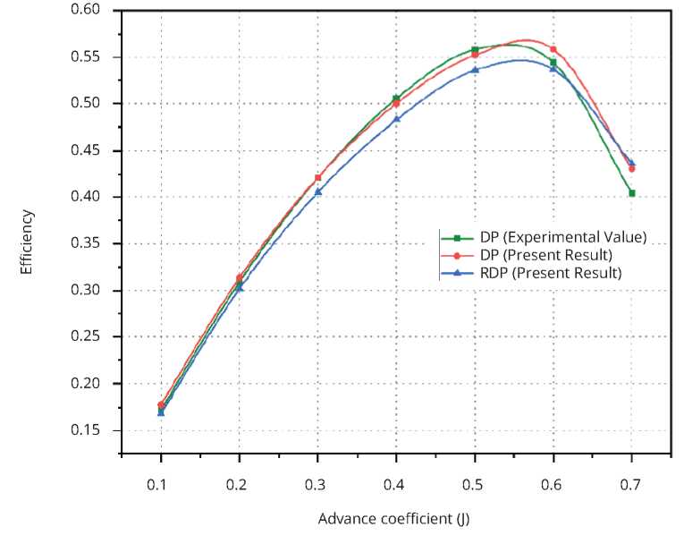
The present study investigated the hydrodynamic characteristics of both DP and RDP configurations. The geometries of DP and RDP are identical, except for the addition of a rotor in the RDP configuration. Numerical simulations were carried out using the RANS equations with the SST turbulence model. A Ka-Series propeller and a modified +19A duct were selected for the analysis, and the numerical results for hydrodynamic characteristics were obtained. Based on these results, the following conclusions can be drawn:
[1] MASOUMPOUR M, GHASSEMI H, MOUSAVIZADEGAN H, HE G. Numerical study on the hydrodynamic performance of rim-driven propulsion featuring a modified duct 19A. 2025, 4 (to be published).
[2] GONG J, DING J, WANG L. Propeller-duct interaction on the wake dynamics of a ducted propeller. Physics of Fluids. 2021, 33(7). https://doi.org/10.1063/5.0056383.
[3] RAZAGHIAN AH, GHASSEMI H. Numerical analysis of the hydrodynamic characteristics of the accelerating and decelerating ducted propeller. Zeszyty Naukowe Akademii Morskiej w Szczecinie. 2016(47 (119):42-53. https://doi.org/10.17402/147.
[4] MOTALLEBI-NEJAD, M., BAKHTIARI, M., GHASSEMI, H. et al. Numerical analysis of ducted propeller and pumpjet propulsion system using periodic computational domain. J Mar Sci Technol 22, 559-573 (2017). https://doi.org/10.1007/s00773-017-0438-x
[5] CHAMANARA M., GHASSEMI H., FADAVIE M., GHASSEMI M.A., Effects of the Duct Angle and Propeller Location on the Hydrodynamic Characteristics of the Ducted Propeller, Ship Science & Technology - Vol. 11 - no. 22 - (41-48) January 2018, https://doi.org/10.25043/19098642.162
[6] GHASSEMI H., MAJDFAR S., FOROUZAN H., Calculations of the Hydrodynamic Characteristics of a Ducted Propeller Operating in Oblique Flow, Ship Science & Technology - Vol. 10 - no° 20 - (31-40) January 201.
[7] JIANG H, WU H, CHEN W, ZHOU P, ZHONG S, ZHANG X, ZHOU G, CHEN B. Toward high-efficiency low-noise propellers: A numerical and experimental study. Physics of Fluids. 2022; 34(7). https://doi.org/10.1063/5.0098891.
[8] LU NX, BENSOW RE, BARK G. Large eddy simulation of cavitation development on highly skewed propellers. Journal of Marine Science and Technology. 2014, 19:197-214. https://doi.org/10.1007/s00773-013-0240-3
[9] PHILLIPS AB, TURNOCK SR, FURLONG M. Evaluation of manoeuvring coefficients of a self-propelled ship using a blade element momentum propeller model coupled to a Reynolds averaged Navier Stokes flow solver. Ocean Engineering. 2009, 36(15-16):1217-25. https://doi.org/10.1016/j.oceaneng.2009.07.019.
[10] LIN, J., et al. Hydrodynamic performance of a rim-driven thruster improved with gap geometry adjustment. Engineering Applications of Computational Fluid Mechanics 17. (1) (2023): 2183902. https://doi.org/10.1080/19942060.2023.2183902.
[11] VEGAA.,LÓPEZMARTÍNEZD.,Reenactment of a bollard pull test for a double propeller tugboat using computational fluid dynamics, Ship Science & Technology - Vol. 8 - no 17 - (9-18) - 2015.
[12] WEI X, YAN T, SUN T, LIU S, DU H. Research on the hydrodynamic performance of propellers under oblique flow conditions. Proceedings of the Institution of Mechanical Engineers, Part M: Journal of Engineering for the Maritime Environment. 2024:14750902241231349. https://doi.org/10.1177/14750902241231349.
[13] GAGGERO, S., VERNENGO, G., VILLA, D., & BONFIGLIO, L. (2020). A reduced order approach for optimal design of efficient marine propellers. Ships and Offshore Structures, 15(2), 200-214. https://doi.org/10.1080/17445302.2019.1606877.
[14] HASSANNIA, A., & DARABI, A. (2013). Design and performance analysis of superconducting rim-driven synchronous motors for marine propulsion. IEEE Transactions on Applied Superconductivity, 24(1), 40-46. https://doi.org/10.1109/TASC.2013.2280346.
[15] LIANG, J., ZHANG, X., QIAO, M., ZHU, P., CAI, W., XIA, Y., & LI, G. (2013). Optimal design and multifield coupling analysis of propelling motor used in a novel integrated motor propeller. IEEE transactions on magnetics, 49(12), 10.1109/TMAG.2013.2241776.
[16] LI C, LIU N, SU J, HUA H. Vibro-acoustic responses of a coupled propeller-shaft-hull system due to propeller forces. Ocean Engineering,173, 2019, 460-468. https://doi.org/10.1016/j.oceaneng.2018.12.077.
[17] SHARKH, S.M.; LAI, S.H. Slotless PM brushless motor with helical edgewound laminations. IEEE Trans. Energy Convers. 2009, 24, 594-598. https://doi.org/10.1109/TEC.2009.2025423
[18] MATUSZEWSKI, L., Ring thruster - a preliminary optimisation study, Polish Maritime Research, 1(59) 2009 Vol 16; pp. 43-46, https://doi.org/10.2478/v10012-008-0009-5.
[19] Cao QM, Hong FW, Tang DH, Hu FL, Lu LZ. Prediction of loading distribution and hydrodynamic measurements for propeller blades in a rim driven thruster. Journal of Hydrodynamics. 2012; 24(1):50-7. https://doi.org/10.1016/S1001-6058(11)60218-7
[20] SONG S, DEMIREL YK, ATLAR M. Penalty of hull and propeller fouling on ship selfpropulsion performance. Applied Ocean Research. 2020; 94:102006. https://doi.org/10.1016/j.apor.2019.102006
[21] CAI B, MAO X, XU Q, CHAI W, TIAN B, QIU L. Simulation ofthe interaction between ship and ducted propeller with a modified body force method. Ocean Engineering. 2022; 249:110950. https://doi.org/10.1016/j.oceaneng.2022.110950
[22] MENTER, F.R. Two-equation eddy-viscosity turbulence models for engineering applications. AIAA J. 1994, 32, 1598-1605. https://doi.org/10.2514/3.12149
[23] DUBAS AJ, BRESSLOFF NW, SHARKH SM. Numerical modelling of rotor-stator interaction in rim driven thrusters. Ocean engineering. 2015;106: 281-8. https://doi.org/10.1016/j.oceaneng.2015.07.012
[24] MAJDFAR S, GHASSEMI H, FOROUZAN H, ASHRAFI A. Hydrodynamic prediction of the ducted propeller by CFD solver. Journal of Marine Science and Technology. 2017; 25(3):3. https://doi.org/10.6119/JMST-016-1214-2
[25] FENG D, YU J, HE R, ZHANG Z, WANG X. Improved body force propulsion model for ship propeller simulation. Applied Ocean Research,104, 2020, 102328. https://doi.org/10.1016/j.apor.2020.102328.
[26] HU J, LI T, GUO C. Two-dimensional simulation of the hydrodynamic performanceofacycloidalpropeller.Ocean Engineering. 2020; 217:107819, https://doi.org/10.1016/j.oceaneng.2020.107819.
[27] ZHANG S, ZHU X, ZHOU ZL. Hydrodynamic performance analysis of hubless rim-driven propulsors. Applied Mechanics and Materials. 2013; 256:2565-8. https://doi.org/10.4028/www.scientific.net/AMM.256-259.2565.
[28] KORONOWICZ, T., KRZEMIANOWSKI, Z., TUSZKOWSKA, T. SZANTYR, J.A., A complete design of ducted propellers, using the new computer system, Polish Maritime Research 2(60), 2009, Vol 16; pp. 34-39, https://doi.org/10.2478/v10012-008-0019-3
[29] MAJDFAR S, GHASSEMI H, FOROUZAN H, ASHRAFI A. Hydrodynamic prediction of the ducted propeller by CFD solver. Journal of Marine Science and Technology. 2017;25(3):3. https:/doi.org/10.6119/JMST-016-1214-2.
[30] YANG, C., et al. "Numerical study of relationships between flows and structural characteristics of the rotor in a rim-driven hubless thruster using a strongly-coupling FSI algorithm." Ocean Engineering, 323 (2025): https://doi.org/10.1016/j.oceaneng.2025.120560.
[31] Wang, K.C.; Liu, H.Y.; Tsao, M.L.; Chu, H.H. Ducted propellers with simplified duct profile. J. Shipbuilding. China 1978, 9, 63. https://trid.trb.org/View/148019.