Ship Science dr Technology - Vol. 17 - n.° 33 - (21-32) July 2023 - Cartagena (Colombia)
DOI: https://doi.org/10.25043/19098642.239
Publio Beltrán Palomo 1
Richard García Méndez 2
Luis Antonio Piqueras 3
1Técnicas y Servicios de Ingeniería S.L. Madrid, España. Email: publiobp@tsisl.es
2Técnicas y Servicios de Ingeniería S.L. Madrid, España. Email: deprichard.garcia@tsisl.es
3Técnicas y Servicios de Ingeniería S.L. Madrid, España. Email: luis.piqueras@tsisl.es
Date Received: November 22nd, 2022 - Fecha de recepción: 22 de noviembre de 2022
Date Accepted: February 22nd, 2023 - Fecha de aceptación: 22 de febrero de 2023
Cavitation is an unwanted phenomenon that has been present for more than 50 years in any ship propulsion system. Despite the great technological advances with the use of advanced simulation tools (CFD's), and new technology, we are still far from being able to eliminate it from propellers due to its own operating principle. This phenomenon will continue to occur under certain conditions of operation of the propulsion system of ships.
The consequences of this phenomenon are well known to the Navies, shipowners and naval engineers: reduction of the service life of the propeller and sometimes of the rudder and hull too, reduction of propulsive efficiency, a significant increase in vibrations and noise on board and, consequently, a reduction in comfort conditions and stealth capacity, together with noise pollution with negative effects on the oceans and marine fauna. This issue has been on the table at the IMO since 2008, currently working on updating MEPC.l/Circ.833. For this purpose, a working group of more than 120 experts from 40 entities (countries and organizations) from all over the world has been created, being TSI one of its most involved members.
After more than 5 years of research, TSI has developed the first non-intrusive system capable of automatically and continuously detect this phenomenon and quantify its intensity, with sufficient precision to provide valuable information for its control. By having a visible and real time indicator of this phenomenon, we can act and reduce the negative effects of cavitation and control the acoustic signature of our vessel at all times.
Key words: Cavitation, Monitoring, Efficiency, URN, Noise, Vibrations.
La cavitación es un fenómeno no deseado que ha estado y está presente desde hace más de 50 años, en cualquier sistema de propulsión de los buques. A pesar de los grandes avances tecnológicos con el empleo de herramientas avanzadas de simulación (CFD's), nuevas tecnologías y procesos de diseño y fabricación, aún estamos lejos de poder eliminarlo de las hélices debido a su propio principio de funcionamiento. El fenómeno de cavitación se va a seguir produciendo en determinadas condiciones de calados y operación del sistema propulsor de los buques.
Las consecuencias directas de este fenómeno son bien conocidas por las Armadas, armadores e ingenieros navales: reducción de la vida útil de la hélice y a veces también el timón y el casco, reducción de rendimiento propulsivo, un aumento significativo de las vibraciones y ruidos a bordo y, en consecuencia, disminución de las condiciones de confort y de la capacidad de sigilo, junto con una contaminación acústica con efectos negativos en los océanos y sobre la fauna marina. Esta problemática se encuentra en la mesa del IMO desde 2008, organismo internacional que actualmente está trabajando en la actualización de la MEPC.l/ Circ.833. A tal efecto, se ha creado un grupo de trabajo de más de 120 expertos, de 40 entidades (países y organizaciones) de todo el mundo, siendo TSI uno de sus miembros más involucrados.
Tras más de 5 años de investigación, que comenzó en el marco del Proyecto AQUO "Achieving Quiet Oceans”, financiado por el 7mo Programa Marco de la Unión Europea, TSI como PYME española ha desarrollado y lanzado al mercado el primer sistema no intrusivo capaz de detectar automáticamente y en continuo este fenómeno desde su inicio y cuantificar su intensidad, con suficiente precisión para proporcionar así una información muy valiosa para su control. Al tener un indicador visible y en tiempo real de este fenómeno, podemos actuar y reducir los efectos negativos de la cavitación y controlar la firma acústica de nuestro buque en todo momento.
Palabras claves: Cavitación, Monitoreo, Eficiencia, URN, Ruido, Vibraciones.
The undesirable phenomenon of cavitation has represented in recent years one of the greatest challenges for modern naval engineering, giving rise to problems ranging from reliability, performance, to its impact on both the ship (noise and vibrations) and the marine environment (acoustic signature and "stealthy").
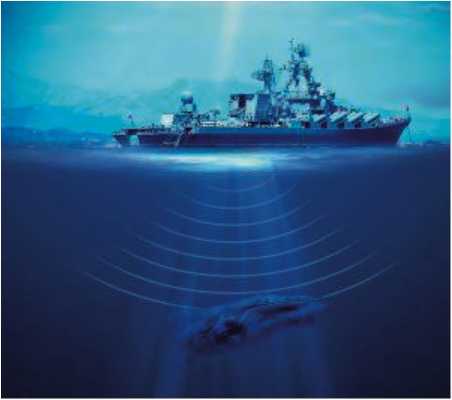
The noises radiated by ships into the marine environment coincide with those used by a large number of marine species for orientation and mating, mainly species such as cetaceans and other marine mammals. In addition to these aspects, the various regulatory bodies are giving increasing importance to reduce the noise emitted by the ships, preparing to regulate them strictly in the not-too-distant future.
Fig. 1. URN and marine lifeforms.
TSI, within several R&D projects, has been working, in the last five (5) years, in the development of a non-intrusive cavitation detection system that allows to know, in a simple, effective and real time way, when and how cavitation occurs in ships as well as its severity making possible to adapt the operating conditions of their ships and prevent cavitation from occurring.
Thanks to the application of this technology, ships will have a much easier way to adapt to the new requirements, while avoiding damage to the marine environment in the areas where they sail.
The basic function of a propeller on a ship is to move it, transforming the power and torque coming from the main propulsion engines into thrust in the proper direction and direction. To achieve this effect, propellers, when turning, produce a pressure gradient on their blade faces. While on the rear face (pressure face) there is a pressure rise, on the opposite face, the front face (suction face), there is a noticeable pressure drop.
It is the combination of these pressure gradients that results in thrust, which is used to move the vessel, but, at the same time, if the speed of rotation of the blades reaches excessive values, on the face where the pressure drop occurs (suction face) the water can reach the vapor pressure, boiling at the ambient temperature. When the bubbles of steam separate from the surface of the blade dragged by the flow, they are exposed again to the normal pressure of the medium, collapsing violently and, consequently, generating pressure pulses and high levels of random broadband noise that are very harmful, both for the surrounding environment, the propeller itself and the comfort of the ship. Figs. 2 and 3 shows the Cavitation Phenomena [3] .
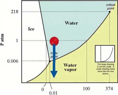
T °C
Fig. 3. Cavitation in naval propeller.

This is the phenomenon known as cavitation, which, from a more technical point of view, can be defined as the hydrodynamic effect produced by the creation of water vapor bubbles at ambient temperature, as a result of the strong pressure gradients produced in the propeller of a ship, following Bernoulli's law.
Within the cavitation phenomenon, there are different types, which can be differentiated in a simple way by how they are produced, and in which areas of the propeller appear:
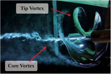
Vortex cavitation: this type is subdivided into two main groups:
Blade tip vortex cavitation: as the propeller blades rotate, flow vortex is produced starting from the high-pressure face at the tip of the blades, and ending in the suction face. In the center of these vortex, the flow can reach very high velocities, which together with the general pressure depression produced by the blades, cause the appearance of this type of cavitation.
Core vortex cavitation: similar to the previous one, but produced by the confluence of the vortex that originate at the roots of the blades and converge in the center of the propeller core.
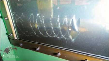
This vortex is dragged by the flow and remains align with the centerline of the propeller, taking the appearance of a braided thread. Its occurrence is less common, as it is a more submerged area of the propeller, and its effects are smaller. See Fig 4.
Fig. 4. Types of vortex cavitation [4].
Laminar cavitation: It occurs in propellers with a high angle of attack, which causes that, under certain rotational speeds, the flow has difficulties to "follow the shape" of the blades.
It remains in a fixed position, being physically separated from the propeller by a thin sheet of fluid, limiting erosion effects on the blades, and having a minor impact on noise, as long as this sheet does not detach from the surface.
Bubble-type cavitation: produced by propellers with highly curved blades in the middle section, producing very high localized pressure drops. This type of cavitation produces very strong vibrations and noises, and severely erodes the propeller blades.
Cloud-type cavitation: typically caused behind areas of laminar cavitation, and resulting from the detachment of this type. Its appearance is easily recognizable as a mist or cloudy area on the suction face of the propeller.
It produces a high amount of noise and vibrations, in addition to a marked erosion of the blades and rudder.
Blade root cavitation: similar to blade tip vortex, but produced at the root. It is less common than the previous ones and is not very damaging, often going unnoticed.
As mentioned above, cavitation arises from pressure gradients that occur on the propeller blade faces. Mathematically we can follow the Bernoulli's equation to explain this phenomenon (See eq 1):
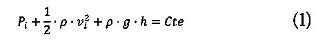
Assuming that the height h (depth in this case) is constant, and taking two points, one on the suction face of the blade and one at a considerable distance from the propeller, we can rewrite the equation (see eq 2):
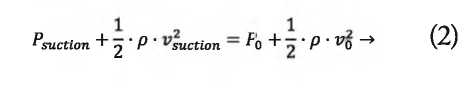
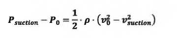
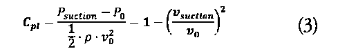
Based on this last equation, we can define the local pressure factor as (eq 3):
As the flow passes around the profile, it accelerates as a function of its geometry and orientation, producing a decrease in local pressure. The graph in Fig. 5 shows the difference in local pressure coefficients.
Fig. 5. Inverted local pressure in propellers [4].

If the pressure at the suction face becomes lower than the vapor pressure of the water, cavitation will start to occur.
Cavitation, from its earliest stages of appearance until it is fully developed, has many consequences, which vary in severity depending on the degree to which the phenomenon is occurring, and of what type it is.
Mainly the following can be highlighted:
High losses of propulsive performance caused by the alteration of the normal flow and the pressure gradient.
Damage of the propeller blades and the rudder: from minor pitting and erosions, to severe damage to the blade surface or edges. If the damage and erosions are too extensive, the propeller blades can even brake, making the propeller unserviceable and inoperable. This can affect the rudder of the ship, with very similar consequences.
Vibrations: in addition to the physical damage, the bubbles, when imploding, transmit a large amount of noise and vibrations to the hull, impairing comfort on board, and also affecting different components and structures.
Noise emitted to the environment (URN): similar to the noise and vibrations transmitted to the hull, part of this noise is radiated directly to the marine environment. This has harmful consequences regardless of the type of vessel, being able to highlight:
In the case of merchant, recreational or civil vessels in general, the noise emitted by ships has a very negative effect on various marine species that mainly use sound to feed or communicate as previously stated, causing the disappearance of individuals of these species in the navigation areas.
In the case of military vessels, this noise emitted to the environment makes it possible to detect the vessels that produce it very easily, which could jeopardize the safety of the mission they are carrying out, as well as the ship itself and its crew.
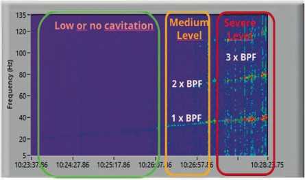
Fig. 6 shows the spectrogram provided by the cavitation system in which the presence of cavitation from low engine revolutions can be appreciated.
Fig. 6. Cavitating ship spectrogram.
It should be taken into account that, in many cases, there is not a single type of cavitation for a given vessel, propeller and conditions, but it can appear sequentially as the propeller speed increases.
Given the impossibility of eliminating this phenomenon, over the years, different methods have been applied to identify and confirm the existence of it on specific existing vessels, all of them being intrusive and/or imprecise.
There are also some formulations that allows the designers to study and predict the behavior of the new ship propellers.
In the case of working on already built vessels, the options available to tackle the cavitation problem are considerably limited, all of them implying the need to previously observe the phenomenon.
For this purpose, the following intrusive methods of detection and definition of cavitation type are mainly used:
Temporary windows installed in the hull: Perforations in the hull in which a glass is installed to allow direct observation of the propeller in operation, involving an appreciable modification of the hull, and the intermediation of classification societies.
Cameras placed external to the hull: Similar to the previous option, but replacing the window in the hull by a camera, which can be installed either on the outside of the hull by means of special supports fixed to it, or inside, in cavities made for it.
In the case of wanting to carry out a cavitation study prior to the construction of the ship, there is more flexibility in order to be able to mitigate this phenomenon to a certain extent.
There are two main methods to predict how cavitation will occur in ships still in the design phase:
Burill's method: seeks to minimize cavitation by approaching the problem from the point of view of increasing the area of the blades, and, in consequence, distributing the thrust over a larger area and reducing the pressure gradient produced on its surface typically using the Burill diagrams, such as the one in Table 1.
Table 1. Keller formulation and Burill diagram [4],
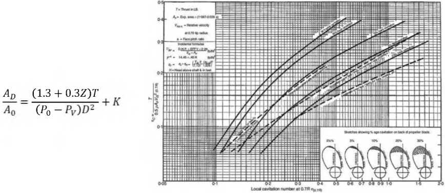
Keller's method: similar to Burill's method, Keller proposes a simplified formulation to determine the ratio of developed area/minimum disk area, based on the characteristics of the propellers and type of vessel and applying a factor named Keller. (Table 1). below shows Keller's formula, together with the K parameter.
Currently, and within the non-military sphere, work is being actively done on the development of regulations and guidelines aimed at controlling the underwater radiated noise emitted by the ships radiated, focusing on preserving the marine environment and ensuring that maritime transport does not cause irreversible damage to the oceans and its lifeforms.
Three initiatives can be highlighted in this respect:
On behalf of Transport Canada, a working group, the UVNRT, has been formed to establish a series of recommendations and Guidelines aimed at controlling noise radiated into the water in Canadian waters, but which are extrapolable to other shipping areas. Canada is one of the most active countries in these aspects and, for the protection of the killer whale reserve in New Colombia, is giving economic incentives in the port of Vancouver for those ships that have adopted measures to control their acoustic signature.
The IMO is in the process of updating the URN Guidelines MEPC.l/Circ.833, developed in 2012, tightening the limits that had been set in the previous version, as well as adding new recommendations.
Added to Transport Canada and IMO, a set of standards is being developed that establishes noise and URN emission limits for merchant ships, depending on their type and characteristics and which will be mandatory: the ISO-3. It is important to highlight the activity of the Spanish flag in these activities.
Both the regulations under development, as well as the Guidelines, take into great consideration the cavitation of the propellers, as they identify this phenomenon as one of the main responsible for the acoustic pollution of the oceans.
Given the rapid development that the different regulations are suffering, ships will soon have to comply with strict radiated noise limit levels, in order to adapt to the regulations, and to be able to continue to sail freely in the different zones of the oceans.
In addition, it must be taken into account that the application of advanced and specific design methods for each ship represents very high costs and efforts, which not all shipowners and shipping companies are willing or can afford.
In already built ships, although it is possible to take actions such as the design of new propellers, or the installation of appendages and hull modifications, again, it represents very high costs, in addition to requiring the interruption of the merchant work or missions of the affected ship, resulting in huge losses for the shipping companies.
Another option, applicable to both new and existing vessels, is to delimit the operational conditions in which the vessel can work, seeking to avoid reaching a condition in which cavitation appears, at least when crossing regulated or particularly sensitive areas. However, this implies delays in the works of the vessel, in addition to being complicated by traditional methods to determine when the vessel is cavitating with accuracy.
Consequently, the application of current methods brings with it a series of drawbacks:
The commonly used methods, in many cases, require the vessel to enter dry dock for installation, with the consequent costs derived from immobilizing the vessel, and the modification itself.
It is necessary to make physical modifications of relative importance to the hull itself, as well as in some cases to the structure of the ship with its consequent impact on the classification of the ship, safety, etc.
The methods mentioned above rely on physical and imprecise observation and assessment of the cavitation, which requires the ship to go through as many sailing situations as possible (not only the typical ones). Any case or situation not observed will be an unknown point.
These aspects of the methods currently used have motivated the research and development, by TSI, of a system that meets a series of minimum requirements, which allow an effective and complete evaluation of the occurrence of cavitation phenomena, as well as their intensity, in any propulsor-hull assembly that may be present:
The system needs to be easy to install and control, so that it doesn't impact negatively on the availability of the vessel or its performance.
It is necessary to ensure that its installation doesn't need deep modifications of the hull or structure for its installation.
That it is adaptable to each type of vessel, regardless of its size, type or function.
It must be able to collect and evaluate data from all possible navigation situations, so that it can be known at all times and in every situation, the cavitation state and condition.
Based on these requirements, throughout several projects, a system has been developed, with the capacity of continuously monitoring, in real time, the situation of the propellers during navigation, determining immediately when cavitation starts to occur and with what intensity.
To achieve this, the system uses one of the most important characteristics of cavitation: the vibrations produced by the implosion of steam bubbles, and transmitted through the ship's hull (structure-borne noise). Fig. 7.
Fig. 7. Frequency broadband spectrums corresponding to cavitation detected in the hull structure.

These random excitations, induced by cavitation and transmitted throughout the ship's hull as "structural noise", reach the different spaces of the ship, especially and not exclusively, the spaces located further aft, and are responsible of the vibrations and noise observed in ceilings, panels, glass, etc. of certain compartments. This random structural noise that propagates through the ship's steel is capable of exciting the frequencies of the different elements of the ship's hull, causing these plates to radiate into the surrounding marine environment with the corresponding alteration in the ship's acoustic or "stealthy" signature.
The vibrations or structural noise induced by the cavitation of the propeller are collected, in this case, by means of a series of high precision and sensitivity accelerometers, which are placed in "hard points” of the structure inside the hull. These points should be areas of the structure in direct contact with an element of the hull close to the propeller, or, failing that, they should have a high stiffness to facilitate the transmission of the referred structural noise.
The signals delivered by these accelerometers are collected by the continuous acquisition system and processed by means of a proprietary analysis algorithm, developed and patented by TSI, which gives the following results:
If the propeller cavitates and with what intensity.
Under what conditions of draft/load, pitch and speed of the propeller(s) the cavitation occurs. The corresponding history is recorded in the system for further studies.
The identification of the type of cavitation based on characteristic patterns of induced vibrations is currently under investigation.
Likewise, the system has been designed to incorporate static parameters such as emissions, consumption, geolocation, etc.
All this is done in real time while the ship is sailing normally, delivering the data continuously to the ship's crew, and allowing them to make reliable decisions at all times based on this information.
The installation of the system, due to its characteristics, also meets the requirement of avoiding long and costly drydocking and major modifications to the ship and its structure, since all parts are installed on the fly and without the need for docking.
The accelerometers are installed in internal points of the ship's structure, which are studied based on their position and stiffness characteristics, with no need to install anything outside the hull or any modification of it (See Fig 8 and 9).
Figs. 8 and 9. Accelerometer placed in the ship structure.

The acquisition and processing system is placed in the vicinity of the sensors to avoid long cable lengths and can transmit the information obtained to the bridge and engine control chamber.
Naval propeller cavitation does not distinguish between ship types, affecting equally (depending on how and what it is designed for) all existing vessels. This makes a system such as the Ni-CDS- Non-intrusive Cavitation Detection System a highly valuable asset for the crew of all ship, regardless of the type and mission of the vessel:
Merchant Ships: The speeds at which these ships usually move are not very high, but the loads to which the propellers are subjected are usually very high, since on the one hand, the propellers of these ships have to move very high amounts of mass, and on the other hand, derived from the need to transport the largest possible amount of goods in the same trip, the shapes of the hull of these ships are not designed with the primary objective of achieving a hydrodynamically efficient behavior.
Consequently, regardless of whether they are oil tankers, bulk carriers, gas carriers or container ships, among others, the propellers of these vessels can produce cavitation at very low speeds, below 8 knots in many cases.
The use of a non-intrusive cavitation detection system in these vessels would bring with it a series of very significant advantages, and of great impact for shipowners and ship operators:
- Reduced propeller, rudder and hull maintenance costs.
- Reduction of emissions and consumption, avoiding drops in propulsive performance.
- Future compliance with developing regulations.
- Greater freedom and ease to avoid navigation restrictions by being able to enter areas with URN requirements, shortening routes and their associated costs.
- Being able to benefit from economic incentives for port stays, as vessels are equipped with a cavitation control system, as well as for early compliance with regulations.
Military Ships: This is one of the segments most interested in controlling the cavitation phenomenon given the "strategic value" of controlling its stealthiness in certain "silent" operating modes.
In this case, the vessels are more efficient from a hydrodynamic and drag point of view, which reduces the propeller's load in their operating conditions, while the propellers themselves are carefully designed to best suit the hulls of their vessels. However, these types of vessels may need to operate at considerably higher speeds than vessels in other sectors, leading to the occurrence of cavitation irremediably.
Far from impacting "only" on propulsive performance, fuel expenditure, and the noise that affects the various marine species, or the damage to the propellers themselves, in the military case, the aspect of stealth, or in other words, detectability, is of particular importance: Military vessels need in a large number of occasions to go unnoticed and undetected and the lack of knowledge of the exact conditions and moments in which cavitation occurs in the propellers of these vessels causes that, due to the large amount of radiated noise produced by this phenomenon, their stealth capacity is greatly reduced, and they are easy to detect and identify, which poses a risk to the vessel and its crew.
In summary, the main advantages for this type of vessel are:
- Increased knowledge of the navigational condition of the vessel or submarine.
- Being able to maintain a stealth situation in silent operational modes or when required.
- Safety of the crew and the vessel.
Recreational Vessels and Cruise Ships: Vessels in this sector are intended for the enjoyment of their owners. They range from small yachts of small size, to large and luxurious vessels that seek maximum comfort for their occupants.
In the case of small boats, due to the noise produced by the engines and systems themselves, the cavitation phenomenon can go unnoticed, and no advantages can be perceived in the use of a system of the characteristics presented. However, although it is not easily perceived by humans, its impact is present, causing severe damage to the propellers in their operation and reducing their efficiency quickly or even breaking the propeller, which ends up leading, irremediably, in the need to change it.
In the case of larger and luxury vessels, their owners or passengers, the last thing they want to hear is the typical crackling of cavitation on board. If the noise of this phenomenon is perceived, even in the slightest, it could lead to the rejection of the vessel by the buyer or complaints from the passengers, with consequent financial losses for all parties involved.
The fact that the captain has real time information on the state of the propeller in terms of cavitation will allow him to adjust to the sailing conditions to avoid the occurrence of this phenomenon at all times, thus maintaining maximum comfort on board.
The first full-scale validation tests of the cavitation detection algorithm were performed within the "On-site Measurements and Assessment" work package lead by TSI, in the framework of the European Project AQUO- Achievement Quiet Oceans, funded by the European Commission. Full-scale vibration measurements were carried out on different types of ships, on the stern structure of the vessels.
Currently, and within the SATURN project framed in the H2020 program, financed by the European Commission, during the experimental tests at full scale on board the ship "Angeles Alvariño", owned by the IEO- Spanish Institute of Oceanography, another complementary validation of the non-intrusive cavitation detection system was done. The aim is to determine precisely when cavitation occurs and its application to avoid the increase of URN and damage to marine fauna.
Based on the authors experience as noise and vibration consultants in the maritime sector, both nationally and internationally, their professional involvement has been required in certain cases of ships suspected of having cavitation in their propulsion systems. From the recording and processing of the vibration signals in the structure of these vessels by means of the non-intrusive detection system, the presence of cavitation has been verified and confirmed, in some cases, very severe as confirmed by the graphs shown in Table 2.
Table 2. Cavitation indicators obtained by the Ni-CDS.

Note: For confidentiality reasons, none of the vessels shown in the top images corresponds to the spectrograms in the second row.
Finally, it was decided to perform a complementary verification at CEHIPAR in its cavitation tunnel. Fig. 10. shows some of the data obtained from this measurement.
Fig. 10. Verification results of the Ni-CDS.
Based on the preceding points of this article, the following observations stand out:
Cavitation, as a hydrodynamic phenomenon, has been a problem for the shipbuilding industry for more than 50 years. This phenomenon continues to cause high costs, both directly in the components: propeller, rudder and hull of the ship and its shortened life and maintenance; and indirectly in the propulsive performance of the ship and its emissions of both gases and noise radiated into the water. This has led to the direct involvement of international maritime organizations such as the IMO and the different states, like Canada with initiatives to reduce the noise radiated by ships, to which the Spanish flag has joined, among others. This means that, although it may be difficult for some shipowners to understand this reality, the guidelines under development will end up becoming mandatory regulations.
In this sense, the authors, as experts in the dynamic-acoustic design of "silent" ships and in the context of their professional activity, have been observing that there are more and more Contractual Specifications in which there is a specific section on control of radiated noise to water, not only for oceanographic vessels, but also for all types of commercial vessels, demonstrated throughout the measurement campaigns in SATUNR, AQUO, or SILENTV, with abundant experimental data showing that the presence of the cavitation phenomenon in the propulsion system of any commercial or military vessel is associated not only with an increase in the entire spectrum of noise radiated into the water at low frequencies of 10 to 1000 Hz, but also with a significant increase in amplitudes (pressure in dB ref. 1 Pa) in the frequency range from 1 kHz to 100 kHz. Wich can interfere with come electronic equipment, like echosounders.
In the case of military ships and submarines, their non-detectability and, therefore, their "stealthiness" has a strategic value to guarantee the success of their missions, as well as the safety of the ship/submarine and its crew.
These aspects, together with the economic costs and their impact on the operation of the ship, detailed in this article, make continuous monitoring of ship propeller cavitation essential. The authors, with more than 46 years of experience in vibration and noise control on ships, decided together with the RDI team that, since cavitation cannot be eliminated for certain operating conditions, the only practical and operational solution was the design of a system that would allow its continuous control for different operating conditions.
[1] JOHAN BOSSCHERS. (2018). Propeller tipvortex cavitation and its broadband noise. PhD thesis, Maritime Research Institute Netherlands.
[2] J. M. ARROYO ROSA. (2018). Cavitación. Temarios formativos.
[3] RAÚL MIGUEL SAN FRUTOS. (2016). Cavitación en hélices. https://conbdebarco.wordpress.com/
[4] Escuela Técnica Superior de Ingenieros Navales. (2016). Propulsión del buque C8.- Cavitación.
[5] Wikipedia, la enciclopedia libre (2017). Cavitación. https://es.wikipedia.org/wiki/Cavitación.
[6] SANDRO IANNIELLO. ANDREA DI MASCIO. Hydroacoustic characterization of a marine propeller through the acoustic analogy.
[7] SANDRO IANNIELLO. The underwater noise prediction from marine propellers: An essentially nonlinear problem.
[8] SANDRO IANNIELLO. Sheet cavitation noise prediction from a marine propeller.
[9] Entregables del proyecto europeo SILENTV Project.
[10] Entregables del proyecto europeo AQUO Project.
[11] Entregables del proyecto europeo SATURN Project.
[12] PUBLIO BELTRÁN. et al. (2012). Achievement of the new URN requirements. ECUA
[13] PUBLIO BELTRÁN. La Construcción Naval Española preparade para responder a los nuevos y exigentes requerimientos medioambientales. Nuevos retos y oportunidades.
[14] PUBLIO BELTRÁN. (2008). Buque Oceanógrafico Miguel Oliver: La excelencia en ruido y vibraciones a bordo cumpliendo ICES n°109