
Ship Science & Technology - Vol. 16 - n.° 31 - (35-42) July 2022 - Cartagena (Colombia)
DOI: https://doi.org/10.25043/19098642.233
Mauricio García 1
Luis Daniel Leal 2
Bharat Verma 3
Nicolás Ruíz 4
1 COTECMAR. Cartagena, Colombia. Email: mgarcian@cotecmar.com
2 COTECMAR. Cartagena, Colombia. Email: lleal@cotecmar.com
3 COTECMAR. Cartagena, Colombia. Email: bharat@cotecmar.com
4 COTECMAR. Cartagena, Colombia. Email: nruiz@cotecmar.com
Date Received: January 15th, 2022 - Fecha de recepción: 15 de enero de 2022
Date Accepted: May 20th, 2022 - Fecha de aceptación: 20 de mayo de 2022
Computational Fluid dynamics (CFD) has become nowadays an important tool in the process of hydrodynamic design of modern ships. CFD is used to model any phenomena related to fluid flow in a control volume like a ship or any offshore structure in the sea. In the present study, the Current force drag coefficients for a Colombian Navy Frigate in deep and shallow water are estimated through application of CFD, which are required to estimate the bollard pull for assisting maneuvers at port. The study shows the process of simulating the ship current drag coefficients using the CFD simulations method which is conducted using STAR-CCM+ software package. The Almirante Padilla class Frigate ship CFD scale model is researched. The results show the ship current drag coefficient calculated considering a current speed of 1 knot with a 90° drift angle for the full-scale ship. The model configuration of the present simulation is based on the procedure recommended and published in the Lloyds Register OCIMF and the UFC mooring report for the estimation of the current drag coefficient.
Key words: CFD, Current draft coefficient, STAR-CCM+, OCIMF, ITTC, Bollard pull.
La dinámica de fluidos computacional (CFD) se ha convertido hoy en día en una herramienta importante en el proceso de diseño hidrodinámico de los buques modernos. El CFD se utiliza para modelar cualquier fenómeno relacionado con el flujo de fluidos en un volumen de control como un buque o cualquier estructura offshore en el mar. En el presente estudio se estiman los coeficientes de arrastre generados por la fuerza inducida por la corriente para una Fragata de la Armada Colombiana en aguas profundas y poco profundas mediante la aplicación de CFD, para estimar la potencia de tiro requerida en las maniobras de asistencia en muelle. El estudio muestra el proceso de simulación de los coeficientes de arrastre de la corriente del buque mediante el método de simulaciones CFD que se realiza mediante el paquete de software STAR-CCM+. Se investiga el modelo a escala de CFD del buque Fragata clase Almirante Padilla. Los resultados muestran el coeficiente de arrastre de la corriente del buque calculado, considerando una velocidad de la corriente de 1 nudo con un ángulo de incidencia de 90° para el buque a escala real. La configuración del modelo de la presente simulación se basa en el procedimiento recomendado y publicado por Lloyds Register OCIMF y en el manual UFC para la estimación del coeficiente de arrastre de corriente.
Palabras claves: CFD, Coeficiente de arrastre de corriente, STAR-CCM+, OCIMF, ITTC, Fuerza de tiro.
The bollard pull capacity corresponds to the available pulling power capacity of a vessel given by its propulsion system. It is the thrust force supplied by the propulsion through a towline to a fixed point located on land when the towline is tensioned and the vessel's ground speed is equal to zero. This value corresponds to one of the most important parameters required to perform berthing/rigging operations and corresponds to the maximum pulling force that a tug will need to ensure safe maneuvering in port. This parameter varies depending on the local weather conditions at the port of arrival or departure, as well as on the hull shape and the respective loading condition of the vessel.
The required drag or draft force is a combination of three main components: the hydrodynamic, aerodynamic and inertial forces that occur during the maneuver. In addition, the hydrodynamic forces can be divided into two main components: a) the forces generated by the waves, and b) the force generated by the current velocity that exists at the location of the vessel's maneuver. Other factors, such as dock construction, under keel clearance and backing thrusters, are also important in estimating the required final draft force.
Simplified formulations are available in the literature to help obtain the magnitudes of these forces. [1]. The most common forms of these equations are described below:
The wind induced forces follow the general form of the drag coefficient defined for fluids. The general form of the equation for the cross-sectional wind force exerted for a vessel is obtained from the guidelines given by the UFC [2] as shown:
Where, Fyw is the transverse force of the wind, pa is the air density, Vw corresponds to the wind speed, Ay is the longitudinal projected area of the vessel, Cyw is the transverse drag coefficient and fyw(θw) is defined as the shape function that takes into account the angle of incidence of the wind.
The current-induced forces also follow the general form of the drag coefficient equation. The CFU document describes it as:
Where, Fyc is the transverse force induced by the current, pw is the density of the water, Vc is the velocity of the current, LwL is the length of the water line, T is the draft, Cyc is the transverse drag coefficient, and θc is the angle of the current direction with respect to the vessel. [2]. The Fig. 1 shows the longitudinal view corresponding to the draft used, and is applied to estimate the projected areas required in the analytical formulation.
Fig. 1. Profile view of the Almirante Padilla Class frigate.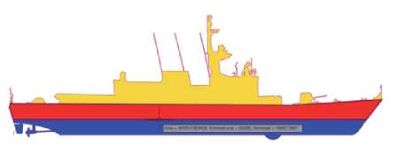
The formulation mentioned in this section considers the effect of shallow water, as well as some predefined constants that can be selected depending on the type of hull being analyzed, in this case specific constants for ships and barges are included.
Considering a zero towing speed, the wave-induced force can be estimated using the formula found in the DNV guidelines [3] guidelines, as indicated:
Where, pw is the density of water, g is the acceleration of gravity, R is the reflection coefficient assigned according to the shape of the object, and Hs which represents the average wave height in the area. The wave induced force increases linearly with velocity and can be described by the following equation:

Where, FWD is the force induced by the waves with a forward speed of 0, and B11 is the damping constant of the wave force.
This force is the sum of the forces generated by the moving object within a fluid and the inertia forces represented by the surrounding fluid, added mass. [3]. The inertial forces of the floating object in motion can be expressed by the following equation:
The added mass "A" is a function of the added mass coefficient:
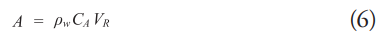
Where, CA is the added mass coefficient, pw is the density of water and VR is the reference volume of the object.
To determine the required pulling force for a maneuver, all previously defined parameters must be calculated following the appropriate assumptions effective for each case, as well as adding a suitable safety margin to ensure a safe maneuver.
The use of CFD tools to solve the equations describing the behavior of a fluid corresponds to an alternative method to estimate the forces generated by the interaction of a fluid flow and a floating body. The set of equations that define the behavior of fluid flow corresponds to the equations of continuity, mass, conservation of energy and momentum, also known as Navier Stokes equations. [4]. These equations can take into account effects such as instability, convection, pressure and viscous effects of a fluid, as well as volumetric forces affecting the phenomenon. The general form of the Navier Stokes equation [5] equation can be expressed in a simplified form as shown below:
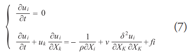
The solution of this system of equations is possible for certain cases in which some reductions are valid. For other cases it is possible to use numerical methods and obtain an approximate solution.
Currently, with the help of computational capabilities the application of numerical methods such as the RANS (Reynolds Averaged Navier Stokes) equations coupled to turbulence models related to the mean and fluctuating velocities of a flow, which allow to deliver a very approximate solution. This method corresponds to the one most commonly used in modern CFD packages such as STAR-CCM+, FLUENT, etc.
In order to meet the current needs of the Colombian Navy and perform adequate and safe docking maneuvers at the Naval Base located in Malaga Bay in the Western Pacific of Colombia, the analysis of the maximum pulling force required for a tugboat to assist the docking and departure maneuver of ships operating in the area is required.
The maritime characteristics of the area make docking and sailing maneuvers a complex task, especially at times when local weather conditions are not favorable.
The meteorological conditions considered for the analysis take into account the effects of tide-induced currents near the pier of a velocity of 1 knot, and wind gusts from the south-west reaching up to 17 knots [6].
For the analysis, the largest vessels operating in the area will be used, corresponding to the Almirante Padilla Class frigates, whose main characteristics are described in Table 1.
Table 1. Main Characteristics of the Frigate.
For the analysis, the largest vessels operating in the area will be used, corresponding to the Almirante Padilla Class frigates, whose main characteristics are described in Table 1.
The above equations (Equation 1 - 6) correspond to simplified models that can be used to estimate the forces present during docking and sailing operations, however, in order to obtain specific data for the Almirante Padilla class frigate, computational numerical methods, such as Computational Fluid Dynamics (CFD), can be implemented for a more detailed approximation.
This work will focus on the calculation of the current transverse drag coefficient necessary to estimate the forces induced by the current on the ship, which are present in the regular docking and departure maneuvers in the port of Bahía Málaga for the frigate Almirante Padilla Class.
This work follows the general recommendations of the model presented in the CFD review studies of MARIN [7] and Lloyds Register (LR) [8] the OCIMF (Oil Companies International Marine Forum) report for current and wind load predictions for VLCC (VLCC) vessels [9] The study presenting the current and wind drag coefficients interacting with the vessel for different angles of incidence on the vessel.
It is important to mention that for this analysis only the water flow is considered, paying special attention to the maximum drag coefficient generated by the cross sea current; that is, the one produced when the flow is projected in a normal direction on port or starboard side on the hull. The generalized formula used to obtain the drag coefficient considers the submerged longitudinal area:
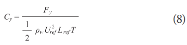
Where, Uref represents the fluid velocity, Lref is the length between perpendiculars, T is the draft of the vessel, and Fy is the total force exerted by the fluid on the hull. Also, the dimensionless Froude and Reynolds relationships are applied:
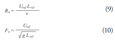
Where v the kinematic viscosity. All CFD calculations presented in this paper make use of the STAR-CCM+ software tool for CFD simulations.
Taking advantage of computational resources, a scale model of the ship is used according to the recommendations of the ITTC (International Towing Tank Conference). [10]. Table 2 shows the recommended scale band according to the Reynolds number of the full-scale ship. The drag formula for the full-scale vessel according to ITTC can be expressed as:

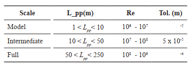
Where 1+k, represents the shape factor obtained from the channel test, CFS is the friction resistance coefficient, CR is the residual resistance coefficient, Δ CF corresponds to the hull roughness factor, CA is the allowable correlation and CAAS is the air resistance coefficient.
Taking into account equations (9) and (11) and the scaling model recommendations according to ITTC on Table 2, the data configuration of the selected CFD scale model to estimate the drag coefficient is presented in Table 3.
Table 3. Scaled data of the CFD model.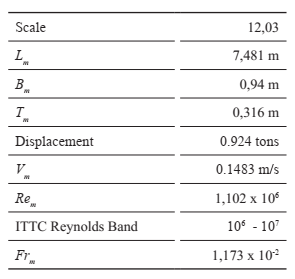
The domain size is designated according to the length between perpendiculars for the numerical simulation according to the LR OCIMF report being: 1.5 L for the fore and aft regions, 2 L starboard and 1 L port, an actual depth of 8 meters and a draft of 3.8 meters, which corresponds to the model scale of 0.532 m and 0.316 m respectively.
Fig. 2. Control volume.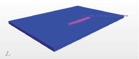
As mentioned above, the present study considers the model configuration recommendations described in the MARIN and LR documents. The boundary conditions applied to the model are:
As for the recommendations given in the LR OCIMF report, the numerical configuration of the CFD model remains fixed, i.e. without any degree of freedom.
This study makes use of the K-Epsilon + SST (Shear Stress Transport) model available in STARCCM+ with a Y+30 value and a total of 10 prism layers near the hull and over the bottom of the domain to capture the drag effects produced by shallow depth.
A mesh model was generated following the general recommendations for a traditional drag simulation (forward flow) without taking into account either the propulsion or steering system.
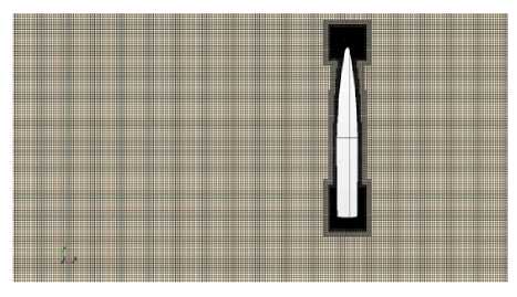
Additional mesh refinements are included to capture flow behavior near the bow and stern. A control volume is also applied to the free surface, although with a smaller number of cells since the simulation works on a subcritical flow; i.e., a Froude number less than 1, and a negligible wave height, as mentioned in the previously cited published work by MARINE and LR. The implemented mesh configuration can be seen in Figs. 3 and 4.
Fig. 3. Longitudinal view of the hull mesh.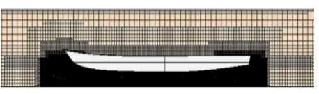
The Cyc calculation is performed with STAR-CCM+ software, and in order to obtain a stable result of the Cyc coefficient, the recommendations given by the ITTC are applied, which indicate that the flow should cross the domain up to 5 times its size at least. Considering the current velocity of 0.1483 m/s, the minimum simulation time was estimated at about 100 seconds.
The calculated value is obtained from the average of the last 50 seconds, once the simulation result has reached a stable condition (no large fluctuations).
The UFC guidelines establish the following set of equations for estimating the value of the transverse drag coefficient.
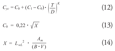
Where, LwL is the length of the vessel at the waterline (m), Am is the submerged cross-sectional area of the vessel at the midsection (m2), B is the beam at the waterline (m), V is the submerged volume of the vessel, (m3), C1 is the current force drag coefficient for shallow water where T/d = 1. 0; for currents of 4.9 ft/s (2.9 knots or 1.5 m/s) or less; a value of C1 = 3.2 is recommended, C0 is the drag coefficient for deep water, T is the mean draft of the vessel (m), d is the water depth (m), and K represents a dimensionless exponent obtained from laboratory data from ship models. For this analytical calculation, the value of K =2 is assigned. Table 4 presents the values used for the analytical calculation.
Table 4. Analytical calculation values according to UFC guidelines to obtain Cyc.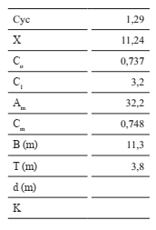
Proceeding to the CFD numerical calculation, the first Cyc coefficient obtained was 2.08, which is considerably higher than the value of 1.29 obtained using the guidelines of the UFC manual.
In order to obtain reliable results, a mesh independence analysis is performed. This analysis consists of increasing the number of cells, making a refinement of the mesh in order to reduce the difference of the immediately comparable results obtained from the coefficient.
A summary of the Cyc results and the refinement process is shown in Table 5. The time-dependent results of Cyc are observable in the Fig. 5. It is important to note that the results with the analytical CFU methodology differ from the results obtained by simulation due to the absence of a more accurate value of the dimensionless exponent K and Co for the type of hull presented in this study.
Fig. 5. Analytical calculation values according to UFC Cyc results over time for different numbers of cells.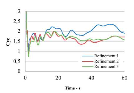
The Fig. 6 shows the variation of the constant K with respect to the change of the transverse drag coefficient Cyc for the UFC formulation. With a value of Cyc of 1.55, as well as a deepwater drag coefficient C0 of 1.0212 obtained using CFD, the value of K that equals Equation 12 would have a final value 1.9.
Fig. 6. Variation of the Cyc coefficient by changing the dimensionless coefficient K and C0 in equation 12.v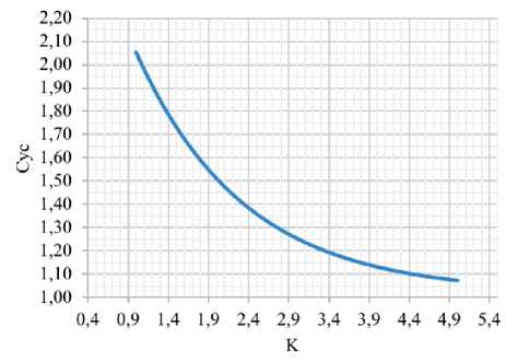
The Fig. 7 shows the velocity field obtained from the CFD simulation. The high-pressure zone with vortices can be observed, which increases the total drag force generated by the stream flow, thus increasing the final value of Cyc, as predicted by the CFD results.
Fig. 7. Stern view showing the presence of vortices.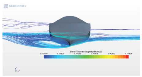
The Fig. 8 provides the velocity field distribution around the vessel showing zones with low velocity magnitudes, which create a high pressure zone thus increasing the drag coefficient acting on the vessel hull.
Fig. 8. Velocity field (top view).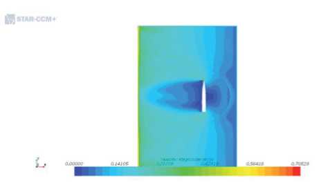
The CFD study has been carried out to estimate the drag coefficient Cyc necessary for the calculation of the pulling force required to estimate the required power of the tugboat with the capacity to perform the maneuvering operations to the ships at the naval base of Bahía Málaga, Colombia.
The simulation setup has been performed based on the recommended procedure published in the Lloyds Register OCIMF and the CFU manual for current drag coefficient estimation.
The analytical formulation provided by the UFC manual to calculate the current drag coefficient Cyc, using the predefined constants applicable to general ships and barges, has shown a lower value in magnitude for Cyc compared to that obtained by CFD analysis. This leads to the conclusion that the current drag coefficient calculated using the UFC guidelines may underestimate the current forces, with CFD analysis being a more reliable method for estimating this coefficient.
From the results it can also be concluded that the Cyc coefficient can vary significantly depending on the hull shape, and in order to use the formulation presented in the UFC manual for the estimation of current induced forces, a safety margin must be included when calculating the required pulling force.
[1] H. HENSSEN, "Tug Use in Port: A Practical Guide," The Nautical Institute, Second Edition, 2003. pp. 69-77.
[2] Department of Defense USA, Unified Facilities Criteria, UFC 4-159-03 Moorings, 2020, pp 54.
[3] DNV, "Recommended Practices DNV-RP-H103- modelling and analysis of marine operations", DET NORSKE VERITAS, 2011, pp 103, pp 28 .
[4] LOTHAR BIRK, Fundamental of ship Hydrodynamics, John Wiley & Sons Ltd,2019.
[5] David Le Touzé, Introduction to numerical simulation - Lecture Notes, Fluid Mechanics Lab, Ecole Centrale Nantes / CNRS, 2015.
[6] E. PEÑA, et al, "Estudio de prefactibilidad ambiental y social sobre la construcción de un puerto de aguas profundas en Bahía Málaga, Pacífico colombiano", Universidad del Valle, Cali, 2010, pp 31.
[7] E. A.J. VROEGRIJK, OCIMF, "CFD current drag" Lloyds Register, Technical Investigation Department, 2017.
[8] A. KOOP, "Shallow water current loads on a LNG carrier using CFD" Proceedings of the ASME 2015 34th International Conference on Ocean, Offshore and Arctic Engineering, 2015.
[9] Oil Companies International Marine Forum (OCIMF), "Prediction of wind and current loads on VLCCs". 2nd edition, 1994.
[10] ITTC, "Practical Guidelines for Ship CFD Applications, " International Towing Tank Conference, 2011.