Ship Science & Technology - Vol. 16 - n.° 31 - (9-17) July 2022 - Cartagena (Colombia)
DOI: https://doi.org/10.25043/19098642.231
Carlos Gutiérrez1
Bashir Yacub2
Enrique Sierra3
Shamir Sánchez4
Juan Contreras5
1 School of Naval Engineering, Escuela Naval de Cadetes "Almirante Padilla". Cartagena, Colombia. Email: cagm.enap@gmail.com
2 School of Naval Engineering, Escuela Naval de Cadetes "Almirante Padilla". Cartagena, Colombia. Email: bashiryacub@gmail.com
3 School of Naval Engineering, Escuela Naval de Cadetes "Almirante Padilla". Cartagena, Colombia. Email: enriquesb1@gmail.com
4 School of Naval Engineering, Escuela Naval de Cadetes "Almirante Padilla". Cartagena, Colombia. Email: shasp1111@gmail.com
5 School of Naval Engineering, Escuela Naval de Cadetes "Almirante Padilla". Cartagena, Colombia. Email: jcontrerasm@gmail.com
Date Received: January 30th, 2022 - Fecha de recepción: 30 de enero de 2022
Date Accepted: June 15th, 2022 - Fecha de aceptación: 15 de junio de 2022
This paper presents the results obtained from the design of a speed and heading control system for the platform component of an unmanned surface vehicle (USV) technology demonstrator, using PID controllers. A description of the vehicle technology demonstrator used for the implementation of the system is presented, as well as the tests performed to obtain the dynamic models of the platform component of the USV technology demonstrator, the calculations of the controllers and the navigation tests that validate the performance of these controllers. All the above as a result of the joint research process between the Naval Cadet School "Almirante Padilla" and COTECMAR, with the support of the Naval NCO School "ARC BARRANQUILLA" and financed by the Colombian Navy through Minciencias.
Key words: Unmanned Surface Vehicle, PID controllers, speed and heading control system.
Este artículo presenta los resultados obtenidos a partir del diseño de un sistema de control de velocidad y rumbo para el componente de plataforma de un demostrador de tecnología de un vehículo de superficie no tripulado (USV), utilizando controladores PID. Se presenta, en primera instancia, una descripción del demostrador de tecnología del vehículo utilizado para la implementación del sistema, además se presentan las pruebas realizadas para obtener los modelos dinámicos del componente de plataforma del demostrador de tecnología de un USV, los cálculos de los controladores y las pruebas de navegación que validan el funcionamiento de dichos controladores. Todo lo anterior como resultado del proceso de investigación conjunta entre la Escuela Naval de Cadetes “Almirante Padilla” y COTECMAR, con el apoyo de la Escuela Naval de Suboficiales “ARC BARRANQUILLA” y financiado por la Armada Nacional de Colombia a través de Minciencias.
Palabras claves: Vehículo de Superficie no Tripulado, controladores PID, sistema de control de velocidad y rumbo.
The use of Unmanned Vehicles for naval applications is gaining more and more importance. This is why worldwide different naval platforms with these characteristics have already been developed and presented. A review of some of these vehicles is presented by (Jinyeong, et al., 2017). But it is necessary to point out that none of these developments is Colombian. This means that if the Colombian Navy decides to use this technology by acquiring any of these prototypes, it will depend technologically on the manufacturer.
With the intention of reducing this technological dependence, the Naval Cadet School "Almirante Padilla" has been working on a navigation control system for this type of vessels. Initially with the development of undergraduate projects oriented to this topic, and later with the execution of research projects financed by the Colombian Navy through Minciencias.
Thus, projects such as the one presented by (Ochoa, et al., 2013) worked on the identification of the hydrodynamic coefficients of a small prototype developed at ENAP which they called "ENAP UNO". On this same prototype (Cardona, et al., 2014) developed their degree project on the adjustment of the coefficients of the NOMOTO model to the dynamics of the USV.
Subsequently, in 2015 ENAP received two USV prototypes called "SÁBALO" with which it boosted its progress in the subject and continued in the development of this line of research. Degree projects such as the one carried out by (Correa, et al., 2017) who worked on the control of PTZ cameras remotely to be implemented in the USV and also implemented a telemetry system for the (Camacho, 2017) implemented a telemetry system for monitoring the navigation angles and geographical position of the prototype.
All of the above was the fundamental input for the formulation and subsequent securing of resources for the execution of project No. 64723. This project developed the navigation control system for the aforementioned prototypes. This, in turn, led to the obtaining of resources for the execution of project No. 75836, a project that is financing the optimization of the communications system and the control station together with its integration to a tactical data system. It is the latter that has given rise to the writing of this article.
The progress made so far on the navigation control system, which continues to be optimized with the execution of this latest project, will be presented.
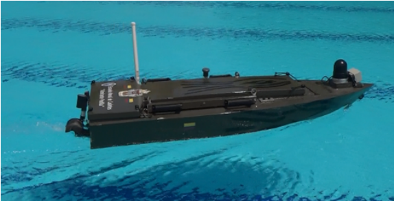
The test prototype consists of a fiberglass monocoque platform with four main cavities. These are intended to house the control system, the battery bank and the propulsion system. The bulkheads separating these cavities are made of wood covered with carbon fiber, and the rest of the volume of this filled with polypropylene. This is to guarantee the buoyancy of the boat even in the event of an accident. An image of the prototype is shown in Fig. 1.
Fig. 1. Test prototype
The USV consists of a jet propulsor driven by an electric motor to give speed to the jet and a steering nozzle to turn it. The overall dimensions of the platform are presented as listed in Table 1.
Table 1. Main Characteristics of the USV.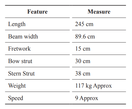
The prototype has the necessary sensors and actuators to implement the navigation control system as shown in Fig. 2. The prototype has a Tx/Rx through which the control signals can be sent to the platform and the platform can send the telemetry to the control station. For the purposes of this work, the control station was implemented in a computer equipped with a second Tx/Rx to complete the data link.
Fig. 2. USV on-board control system.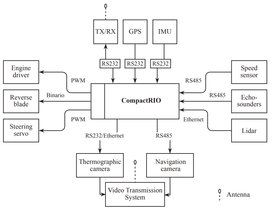
Source: Own
The entire system on the platform is based on a single processing core where all the instrumentation signals are concentrated and from where all the actuators of the platform are manipulated through the aforementioned data link.
The control system is based on two control loops. One loop manipulates the engine power to control the USV speed, while the second control loop is in charge of manipulating the thruster nozzle to control the USV heading. Fig. 3 presents the control scheme to be implemented.
Fig. 3. Control scheme.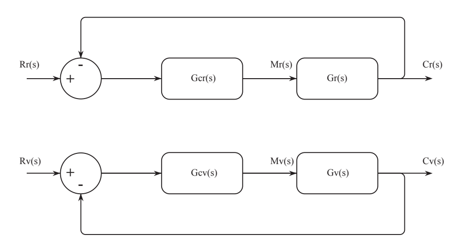
In Fig. 3, the upper control loop will be in charge of heading control while the lower loop will be in charge of speed control.
The "reference", or "set point", signals Rr(s) and Rv(s) come from the control station via the aforementioned data link while the Gcr(s) and Gcv(s) controllers will be programmed in the USV processing core.
The Gr(s) and Gv(s) Models represent the behavior of the vessel for both heading and speed, mathematical models that were obtained from the navigation tests that were performed.
The controllers to be used in both the speed loop and the heading loop are PID controllers.
The navigation test was performed by executing the following steps.
• USV in Initial conditions. This is propulsion and rudder at 0%.
• Phase 1: With rudder = 0% performs one step step in propulsion
• Phase 2: Once the USV has stabilized in speed, perform a rudder step.
Fig. 4 outlines the trajectory that the USV was to describe during the test. The design of this test was based on the IMO Standard for Ship Maneuverability, presented in Resolution MSC.137(76) adopted on December 4, 2002. (International Maritime Organization, 2002).
Fig. 4. Evolutionary Circle test (Taken from EscolaPort).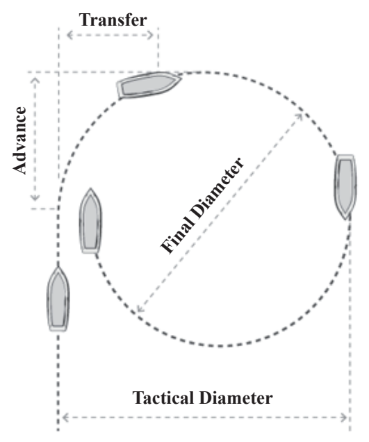
This test made it possible to obtain the speed model achieved with the measurements during the first phase of the test and the turning model during the second phase of the test.
For speed controller tuning, the minimum error integral tuning technique optimized for changes in the reference was implemented.
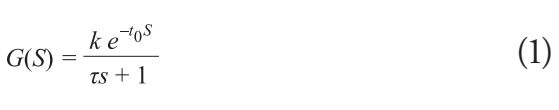
This technique is based on a first order plus dead time model as shown in equation 1. Where k corresponds to the process gain, to corresponds to the dead time and τ corresponds to the time constant.
The values that fit this model to the behavior of the USV will be presented in the results section.
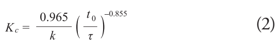
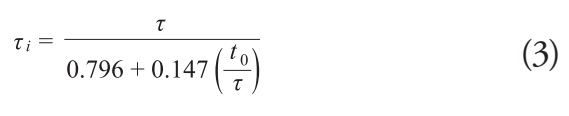
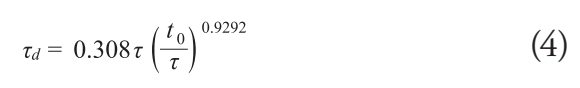
The controller parameters were calculated using equations 2 to 4.
These equations are optimized for the best Integral Time Weighted Absolute Error (ITAE) in the face of a reference change. (Smith, et al., 1997). Other tuning techniques that were explored are presented in (Alfaro, 2002).
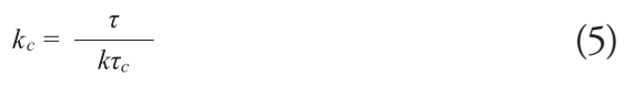
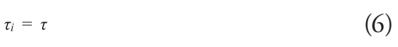
The parameters of the Heading controller were calculated using Dahlin Synthesis. (Smith, et al., 1997). This model is the same as the one presented in equation (1) but with to = 0. Equations 5 and 6 present the calculation for a PI controller.
Where τ is the time constant of the response expected by the system with the implemented control loop.
The navigation tests were carried out in a 50mx25m pool with a minimum depth of 1.5m and a maximum depth of 2.5m, with the water recirculation pumps off. Performing the tests in this way guarantees that the results will not be affected by transverse currents that could affect the trajectory of the boat and present deviations that are not due to the dynamics of the boat.
Fig. 5 shows one of the results obtained in phase 1 of the navigation tests. This test presents the velocity variation starting at instant t = 0, which is the instant at which a 45% CO (Controller Output) height step was performed at the actuator input.
Fig. 5. Velocity Response.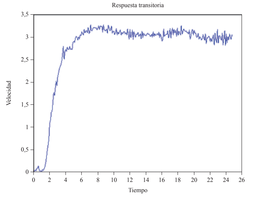
As can be seen the boat reaches an average speed of 3 knots and that the response describes a first order plus dead time behavior.
Similarly, Fig. 6 presents the results of a performance of the tests in phase 2 of the experiment described in section 4.
Fig. 6. Evolutionary Circle test.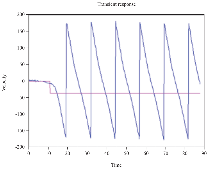
Note that Fig. 6 shows the instant in which the propellant nozzle performs a step step of -74%CO which generates the USV to start turning and perform 5 complete turns. Fig. 7 presents an image of the test in question. The circular wake that the boat describes in the water can be seen.
Fig. 7. USV in Evolutionary Circle test.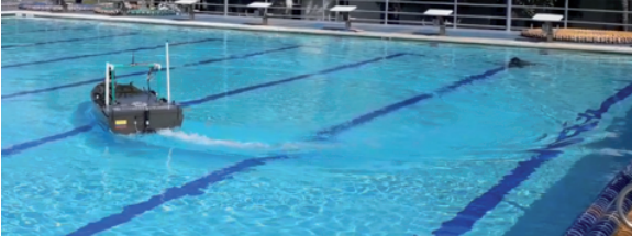
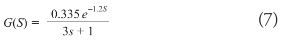
Taking into account the tests and the results obtained in them, for the velocity model it was possible to find the first order plus dead time model that fits the response described by the USV, a fit that is explained by (Smith, et al., 1997). This model is presented in equation 7.
To validate the relevance of the model, SciLab simulation software was used to see both the actual USV response and the model response to the same input. Fig. 8 presents these results.
Fig. 8. Velocity Response Vs Model.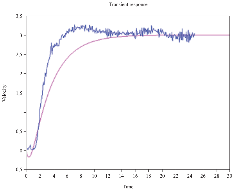
The dead time simulation is observed as a negative curve. But this is because the dead time was simulated using the first order Padé approximation. (Alfaro, 2002). However, it should be noted that the approximation allows to see a response very close to the reality of the system. This is verified by calculating the correlation coefficient between the real response and the model response, which for this case yielded a correlation of 95.2%.
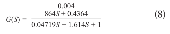
Likewise, the second order Nomoto model was obtained and validated, which is described in equation 8.
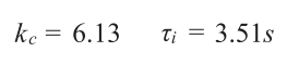
Tuning of the speed controller yielded the following results:
With this controller configuration, simulation tests were performed. Fig. 9 shows the response of the system against an input at the reference of 5 knots.
Fig. 9. Velocity Response Vs Model.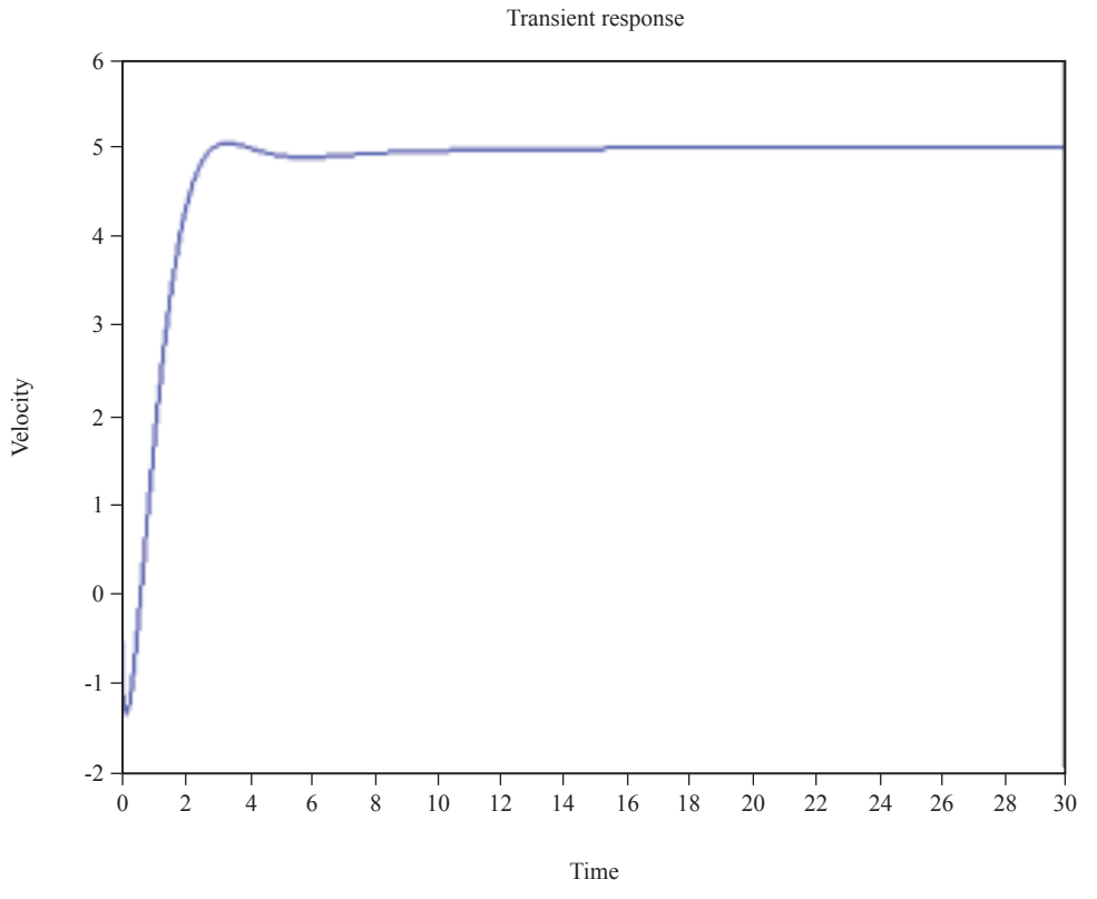
On the other hand, the course controller tuning yielded the following results:
This resulted in a transient response curve as shown in Fig. 10.
Fig. 10. Heading control response.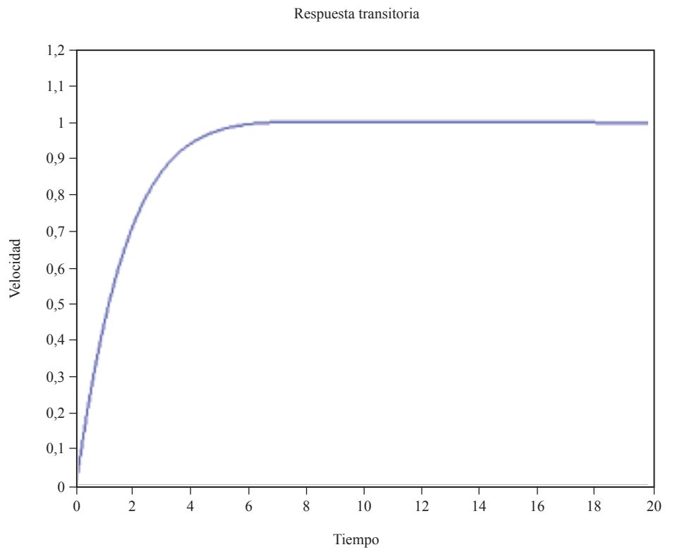
The navigation tests yielded results that allowed to adjust the dynamic models for both speed and heading, showing correlations between the test signals and the simulations of up to 95.2%.
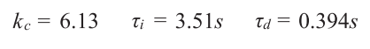
Once the models were adjusted, it was possible to calculate the parameters of the speed controllers. The parameters for the speed controller were Kc = 6.13, τi = 3.51s, τd = 0.394s. and for the heading controller the calculation was Kc = 6.13 y τi = 3.51s.
With the tuning of the controllers it was possible to run simulations that shed light on their behavior. And that will be the reference to determine if the results obtained from the navigation tests with the controllers are valid or not.
The navigation tests to validate the behavior of the controllers have yet to be carried out. These tests should in principle be carried out independently.
This means that for the speed control test the heading controller must be off and for the heading control test the speed controller must be off.
Subsequently, a test should be performed with both controllers operating, but making changes in the references of both controllers at different time instants.
This should make it possible to evaluate to what extent these two control loops can work simultaneously without interfering with each other.
The writing of this article was possible thanks to the joint participation of the Naval Cadet School "Almirante Padilla", COTECMAR and the Naval NCO School "ARC Barranquilla" in the execution of projects No. 64723 and 75836, the latter being the one that has given rise to the writing of this article.
All of the above has been possible thanks to the financing of the aforementioned projects by the Colombian National Navy through MINCIENCIAS.
ALFARO, V. 2002. Tuning Methods For PID Controllers Operating As Regulators. s.l. : Ingeniería, 2002. 21-36.
CAMACHO, D. 2017. Development of the Telemetry System for the Monitoring of Geographic Position, Roll, Pitch and Magnetic Orientation in Unmanned Surface Vehicles "SÁBALO2". Cartagena : Naval Cadet School "Almirante Padilla", 2017.
CARDONA, J and PAIPA, E. 2014. Metodología Para La Obtención De Indicadores de Nomoto a Partitir De Pruebas Experimentales. Cartagena de Indias : Escuela Navala de Cadetes "Almirante Padilla", 2014.
CORREA, N and AMADOR, L. 2017. Implementation of the PTZ Camera Control System By Radio Frequency In Unmanned Surface Vehicles "SáBALO". Cartagena de Indias : Escuela Naval de Cadetes "Almirante Padilla", 2017.
ESCOLAPORT. [Online] [Cited on: 10 April 2021.] https://aulanautica.org/unit/unidad-teorica-7-maniobra-y-navegacion/.
International Maritime Organization. 2002. Standards For Ship Manoeuvrability. s.l. : Resolution Msc, 2002.
JINYEONG, H, JUNGHOON, K and YONGJIN, K. 2017. Analysis of Desing Directions for Unmanned Surface Vehicles (USVs). s.l. : Journal of Computer and Communications, 2017. 92-100.
OCHOA, A and OTERO, E. 2013. Implementación De Técnicas De Identificación Para La Obtención De Los Coeficientes Hidrodinámicos De Vehículos De Superficie Orientados A La Modelación Del USV. Cartagena de Indias : Naval Cadet School "Almirante Padilla", 2013.
SMITH, C and CORRIPIO, A. 1997. Principles and Practice of Automatic Process Control. 1997.