Validating the weldability with flux core arc welding “FCAW” for deteriorated naval steels (FLUX CORED ARC WELDING)
Alfonso Patarroyo1
Elvis Solano2
Fabio Cueca3
Fernando Rojas4
Alfredo Morales5
Abstract
Repairs and changes of steel plates in the structure of the vessels where it is possible to find steels with a high degree of deterioration need reliable welded joints in naval steel of the type ASTM A–131 Gr. A new to old. Due to the fact that the variables associated to the weldability of the materials to be repaired are not known, it is necessary to make a study on the weldability of steel ASTM A131 Gr A, in full penetration seams or junctures, under the various parameters involved in the welding process, to determine the influence of the corroding residues that affect the application of welding compounds through the analysis of the metallurgical reactions of liquid condition in order to select the contributing materials with the alloy elements that are able to prevent these phenomena and to recommend the best practices for the electric arc welding process with tubular electrode with FCAW flux core.
Key words: Weldability, corrosion, flux Cored Arc Welding
Resumen
Las reparaciones y cambios de láminas de acero en la estructura de los buques donde se presentan aceros con alto grado de deterioro, requieren uniones soldadas confiables en el acero naval ASTM A–131 Gr. A nuevo a viejo. Debido al desconocimiento de las variables asociadas con la soldabilidad de los materiales a reparar, es necesario realizar el estudio de la soldabilidad del acero ASTM A131 Gr A, en uniones o juntas de penetración completa, bajo los diferentes parámetros del proceso de soldeo, determinar la influencia de los residuos de corrosión que afectan la aplicación de la soldadura, mediante análisis de las reacciones metalúrgicas de estado líquido para seleccionar los materiales de aporte con elementos de aleación capaces de evitar estos fenómenos y recomendar las mejores prácticas del proceso soldeo por arco eléctrico con electrodo tubular con núcleo de fundente FCAW .
Palabras claves: soldabilidad, corrosión, flux Cored Arc Welding.
Date received: March 2nd, 2009 - Fecha de recepción: 2 de marzo de 2009
Date Accepted: October 6th, 2009 - Fecha de aceptación: 6 de octubre de 2009
________________________
1 Servicio Nacional de Aprendizaje SENA. e-mail: apatarroyo@misena.edu.co
2 Servicio Nacional de Aprendizaje SENA e-mail: elsomon7@misena.edu.co
3 Servicio Nacional de Aprendizaje SENA. e-mail: facum64@hotmail.com
4 Servicio Nacional de Aprendizaje SENA. e-mail: hfrojas@misena.edu.co
5 Corporación de Ciencia y Tecnología para el Desarrollo de la Industria Naval, Marítima y Fluvial COTECMAR. e-mail: amorales@
cotecmar.com
............................................................................................................................................................
Introduction
Studies on the weldability of ASTM A-131grams, naval steel with a high degree of deterioration are scarce. The objective of this study is to establish the behavior of these steels when they are subject to the FCAW (Flux Cored Arc Welding) processes. This process stands out for its high productivity and welding reduction costs as compared to manual processes. It is based on the fact that FCAW is a semi automatic process that reduces the periods of using welding, welding costs and also, they increase productivity by improving several indicators as compared to the SMAW process.
In order to validate the weldability, mechanic practices, micro structural behavior studies as well as studies on the behavior of several commercial tubular wires in Colombia will be conducted.
Basics of the process
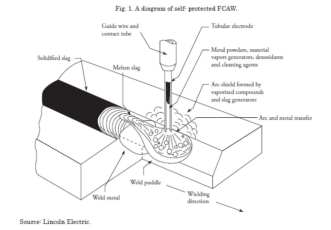
Welding with an electric arc with tubular electrode with flux core FCAW (Flux Cored Arc Welding) is a semi automatic welding process that takes advantage of an electric arc between a continuous electrode of filler metal and the welding electrode and the welding puddle. This process is used with the protection from a flux that can be found into the tubular electrode, with or without an additional gaseous protection from the outside, and without applying any pressure to it.
Experimental Design
The method that has been used to assess the weldability conditions of Steel of the type ASTM A–131 Gr. A, through the FCAW process in the manufacture and repair of vessels, by Cotecmar and Centro de Materiales y Ensayos del SENA, has been based on the characterization of steels of the type ASTM A–131 Gr. A with steel samples of ships built on different years. The following tubular wires were selected for this study in order to be assessed in terms of their behavior before weldability of the naval steel as per the classification ANSI / AWS A 5.20; E71T-1, E71T-8 and E71T-11, which was encoded in this document as -1, -8 y -11 respectively.
Three stages were followed here: characterization of the naval steel, selection of the filler materials and the assessment of the weldability.
Creating the parameters of the welding equipment was performed in order to qualify positions 2G and 3G correspondingly as per code number AWS D1.1:2004
The seam junctures were made with base materials according to the production years and service condition of the vessel. The nomenclature for the base material was set as follows: new material (N), old material (V) and old- welded material (VS); and the resulting combinations were N-VS, V-V and N-V for each one of the junctures part of the research.
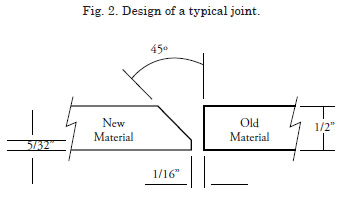
The design of groove butt joints with root size face equivalent to 0 a ![]() root opening equivalent to
root opening equivalent to ![]() and bevel angle and chamfer of 45°.
and bevel angle and chamfer of 45°.
The result analysis was done by simple comparison with: 18 observations in the tension test which corresponded to the 3 combinations per each one of the designation and 2 test tubes per coupon as per the Regulation, 36 observations in the side 3 combinations and 4 test tubes per coupon according to code AWS D1.1 and in the hardness test 36 observations for a total of 720 points obtained, 20 points per test tube). The metallographic analysis had 27 metallographies (3 for each combination and designation), for the base material, welding jobs and the area that had been affected by heat, done in the old material (V) and old welding jobs (VS) whose interest is to verify the weldability behavior in them for the FCAW process.
The AWS D1.1 code criteria were applied here, obtaining the design of the joint of Fig. 2 for which the flame- cutting process was performed in order to generate the coupons on which the welded joints were done following the FCAW process with three electrode wires -1,-8 and -11.
Parameter creation of the Welding Process and calculation of the Heat input (H)
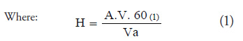
H = Heat input in J/centimieters
A = amperes
V = electrical potencials in volts
Va = Advancing speed in inches / minutes
A = current in amperes
V = voltage in volts
va = advancing speed in inches per minutes
60 = constant
Heat input for position 2G
• Root pass = 64,8 KJ/cm
• Filler pass = 61,8 KJ/cm
• Presentation pass = 60.800,11 J/m
Heat intake for position 3G
• Root pass = 53.647,05 J/m
• Filler pass = 52.258,06 J/m
• Presentation pass = 49.241,37 J/m
Base material characterization
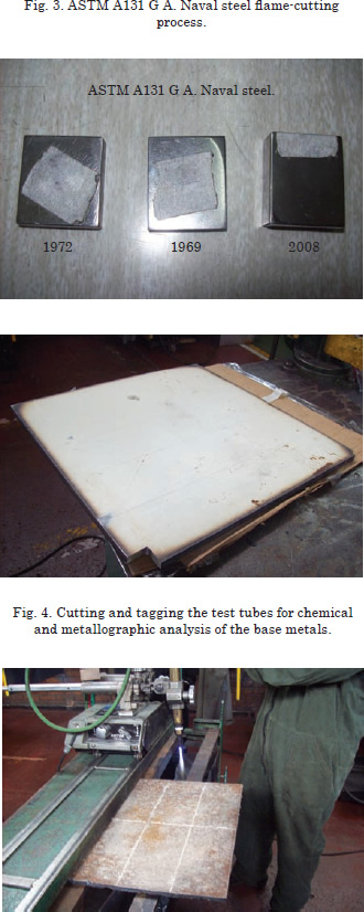
The base material of the test tubes obtained from the plates was characterized during the research, to verify it with ASTM A131 Gr A for Naval Steel, according to what is shown in Fig. 3. Chemical analysis tests were performed by spectrometry thus generating the chemical composition of Table 2, from where it is easy to conclude that the naval steels manufactured in 1969, 1972 and 2008, are typical steels of designation ASTM A131 Gr A.
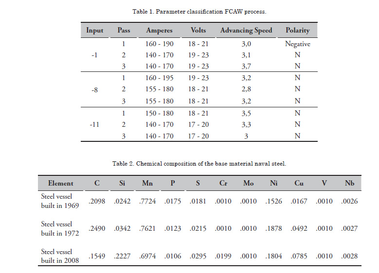
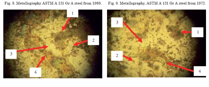
Later, a metallographic analysis was performed and finding bead like segregation bands in the naval steel from 1969 and 1972, (see Figs. 8 and 9) (boxes 1 and 4) on a ferritic matrix (box 3), supposedly due to the aging process due to the precipitation and migration of carbon on ferrite. Also sphere- shaped oxides were found in the ferritic structure (box 2), probably generated by corroding environments in an aqueous or gaseous environment.
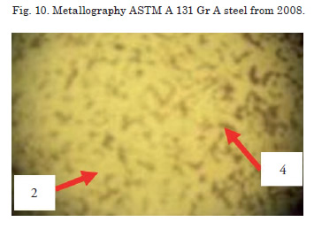
As compared with the micro structure of naval steel from 2008, that shows an evenly distributed beaded ferritic structure as can be seen in Fig. 10.
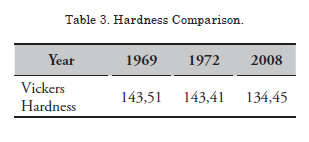
The average Vickers analysis of hardness of the samples of the naval steel from 1969, 1972 and 2008, is consistent with the metallographic analysis. It was possible to obtain hardness indexes greater than that of the steel from 2008, supposedly due to the aging phenomenon due to the precipitation and migration of carbon on ferrite.
Characterization of a Welded Joint
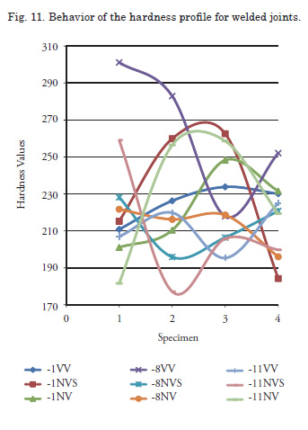
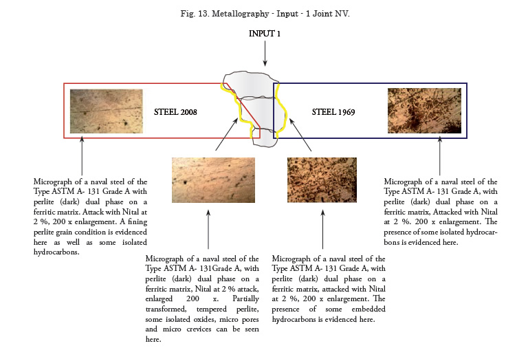
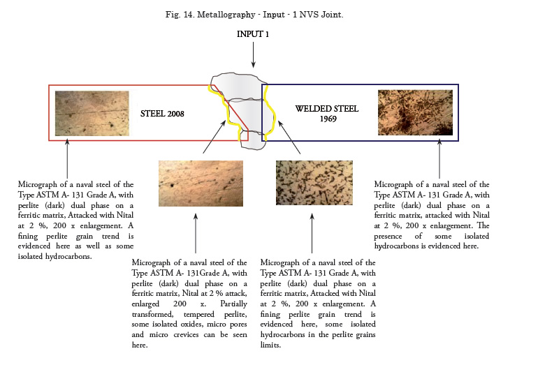
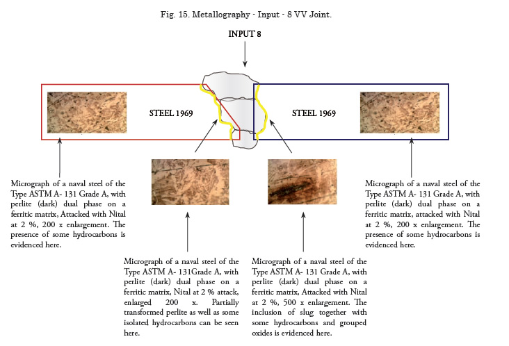
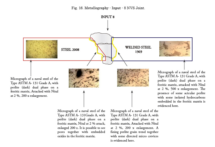
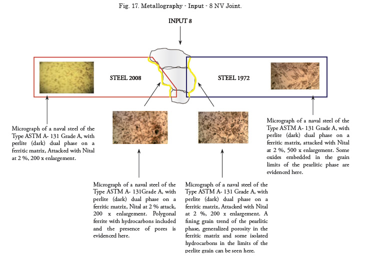
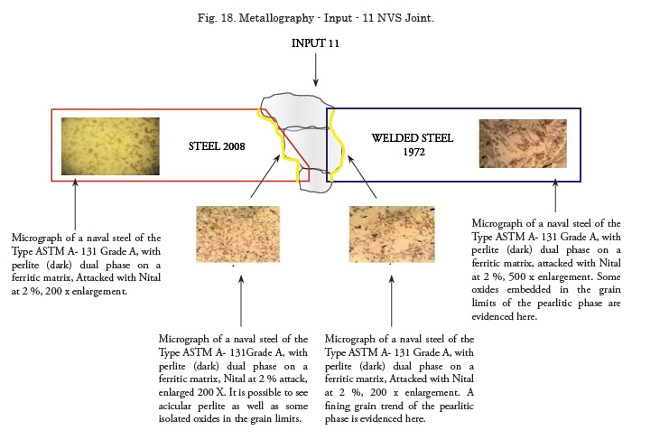
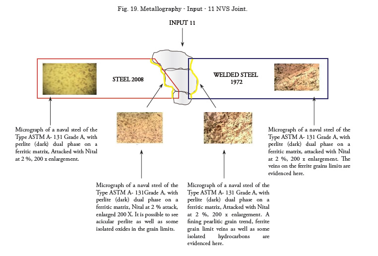
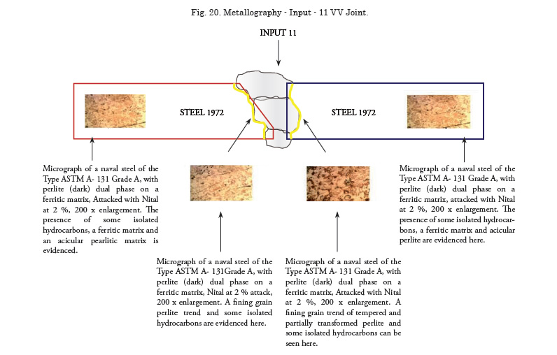
By applying the parameters in Table 1, and the design of the joint in Fig. 2, the FCAW welding process was applied with input -1, -8 and -11, according to what was stated during the experimental design the Joints welded using the visual inspection techniques, colored penetrating fluids, tension destructive test, side crease, metallography and hardness profile.
Regarding the side crease tests, the test tubes with the various combinations had a good behavior and the behavior is acceptable under the criteria in Code AWS D1.1.
Analysis and Conclusions
The average Vickers hardness for all base materials, shows that for years 1969-(143,51) and 1972- (143,41), it is relatively similar and they are higher when compared to the year 2008-(134,45). This is due to the probable hardening caused by its micro component precipitation and the years the materials have been used in the vessel.
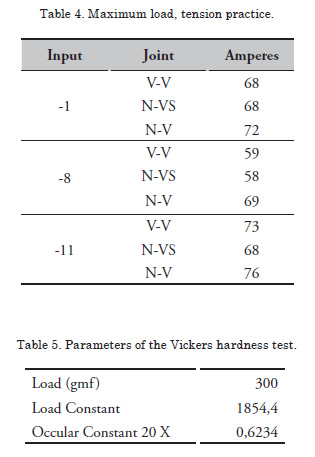
The base materials used in this study exhibited a ferritic matrix with perlite as the second micro component. Mechanical tension tests showed maximum load values, maximum effort values, rupture load and rupture effort within the ranges set by regulation ASTM A131 Grade A for designation -11. Designations -1 and -8 are below the values stated by the regulation and especially -8 whose rupture occurred in the input material.
During welding process FCAW, some welding procedure specifications were generated, as well as the qualification of the welders. The conclusions were that the input materials designated as -1 and -8, require highly trained welders, because managing the welding puddle and especially the slag fluency result in inclusions and lack of penetration in the root of the joint.
The Best behavior was exhibited by the input material designated as -11, since it generates clean welded joints and the welder needs an intermediate training level. It is possible to go from manual coated electrode applications SMAW, to the FCAW process. Calculating the input heat for inputs -1,-8 and -11 generates heat affected areas that are typical in clean steels like ASTM A 131 Gr A.
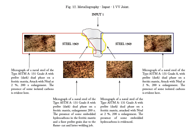
The metallographic analysis concluded that the steels from 1969, 1972 and 2008, even though the first two exhibit pearlitic segregations, this does not affect the welded joints, including the old welding jobs found. A NV welding process should be graded for maintenance cases.
FCAW welding process with AWS E71T-11input material exhibits the best welding results. It developed clean full penetration joints. This behavior allows for unilateral welds in vessels, thus displacing the SMAW welding methods which have partial penetration and root clean up.
Bibliography
ORTÚZAR, Raúl. Mecánica de fracturas en estructuras navales. En: Congreso Panamericano de Ingeniería Naval “XVI COPINAVAL 99”1988
CASTILLA, Iván J. UNFRIED, Jimmy S.
Soldabilidad de un acero microaleado utilizando
el proceso SMAW y metal de aporte ferrítico de
alta resistencia. Revista Ciencia y Tecnología de
Buques Numero 3 Volumen 2. Julio de 2008.
AMERICAN WELDING SOCIETY AWS, D1.1/D1.1 M:2006 Structural Welding Code– Steel No 1.3)
HERRERA MELO, Oscar Javier. FUNDAMENTOS DEL PROCESO, Soldadura por arco con núcleo de fundente"FCAW", 2007.
WELDING HANDBOOK. Volume 2. Welding Processes Chapter.5 p. 159.
WELDING HANDBOOK. Volume 2. Welding Processes Chapter.5 p. 159 - 174.
WELDING HANDBOOK. Volume 2. Welding Processes Chapter.5 p. 163.
WELDING HANDBOOK. Volume 2. Welding Processes Chapter.5 p. 165.
WELDING HANDBOOK. Volume 2. Welding Processes Chapter.5 p. 166.
WELDING HANDBOOK. Volume 2. Welding Processes Chapter.5 p. 170.
WELDING HANDBOOK. Volume 2. Welding Processes Chapter.5 p. 171.
WELDING HANDBOOK. Volume 2. Welding Processes Chapter.5 p. 173.
WELDING HANDBOOK. Volume 2. Welding Processes Chapter.5 p. 174.