Ship Science & Technology - Vol. 15 - n.° 30 - (9-14) January 2022 - Cartagena (Colombia)
DOI: https://doi.org/10.25043/19098642.224
Edgar S. Chávez Hipólito 1
Nain M. Ramos Álvarez 2
José L. Roggero Roggero 3
1Universidad Nacional de Ingeniería. Mechanical Engineer Department. Lima, Perú. Email: echavezh@uni.pe
2Universidad Nacional de Ingeniería. Mechanical Engineer Department. Lima, Perú. Email: nramosa@uni.edu.pe
3Universidad Nacional de Ingeniería. Mechanical Engineer Department. Lima, Perú. Email: jroggeror@uni.edu.pe
Date Received: August 15th, 2021 - Fecha de recepción: 15 de agosto del 2021
Date Accepted: November 21st, 2021 - Fecha de aceptación: 21 de noviembre del 2021
The hull designs of the Peruvian fishing fleet lack hydrodynamic studies, which is why, in the present work, a study of the resistance to the advance of a classical model of the type mentioned, called "MMS", is carried out. An experimental numerical correlation is carried out with this model to validate the proposed methodology.
The numerical methodology uses CFD using Ansys-Fluent software, considering turbulent behaviour for a multiphase fluid (water-air), a mesh with inflation layers and refinements, among other characteristics. The results show a maximum error of 5% in relation to the results obtained experimentally. Based on this methodology, the behaviour of the adaptation of a SEA Arrow type bow to the MMS model is analysed. The results of this new proposal consider a decrease of up to 10% in the total resistance at different operating speeds.
Keywords: Fishing vessel, CFD, SEA-Arrow Bow.
Los diseños de casco de la flota pesquera peruana carecen de estudios hidrodinámicos, es por eso que, en el presente trabajo se realiza un estudio de resistencia al avance de un modelo clásico del tipo mencionado denominado “MMS”. Con dicho modelo se realiza una correlación numérica experimental para validar la metodología propuesta.
La metodología numérica utiliza CFD mediante el software Ansys-Fluent, considerando un comportamiento turbulento para un fluido multifásico (agua-aire), una malla con capas de inflación y refinamientos, entre otras características. Los resultados muestran un 5% de error máximo en relación a los resultados obtenidos experimentalmente. A partir de esta metodología es analizado el comportamiento de la adaptación de una proa tipo SEA Arrow, al modelo MMS. Los resultados de esta nueva propuesta, consideran una disminución de hasta 10% en la resistencia total a diferentes velocidades de operación.
Palabras claves: Embarcación pesquera, CFD, Proa SEA-Arrow.
Peru and, in general, traditional fishing countries recognize that their marine resources are a great source of income, making fishing one of the most important activities for their economy. For this reason, this sector is currently focusing its efforts on improving the performance of its operations to generate a higher profit margin.
Most industrial companies have experienced a growth in their fleet of vessels, however, it is observed that the new vessels have designs without specialized technical support, and in many cases building hulls based on standard models with slight modifications at the request of the owner.
Perhaps, one of the biggest unknowns of these designs is the use of a bow bulb, which is favorable only for some operating situations. In the case of fishing vessels, it is different, since they experience different operations during their navigation, making their draft vary in a very wide range.
The SEA Arrow bow was designed by the Japanese to be applied in LPG carriers, making them more energy efficient compared to their bulb and rounded bow version.
For its study, the design of an adaptation of the SEA-Arrow bow on the Marco Marine Seatlle model, which is a very common hull in industrial fishing vessels of the purse seine type, is taken. A CFD (Computational Fluids Dynamics) analysis is carried out for the forward resistance study, however, in the process it is shown that working with straight and very thin bows brings some extra difficulties that will be developed and solved in this research work.
Based on the recommendations issued by ITTC, a methodology is developed for a numerical analysis to determine the drag of a fishing vessel with a SEA-Arrow bow.
The present research work takes as object of study the Marco Marine Seattle (MMS) ship model with a bow modification adopting the SEA-Arrow type bow (Sharp Entrance Angle bow as an Arrow). The model based on the MMS model is used in the coasts of Peru by companies dedicated to industrial fishing, having this vessel as part of their fleet of purse seine fishing vessels.
The SEA-Arrow bow was developed by Kawasaki Shipbuilding to improve the performance of medium speed vessels such as LPG carriers. This design achieves reduced drag by reducing the power requirement of the main engine by 6-10% compared to the bulbous model with a rounded bow, while maintaining the same volume.
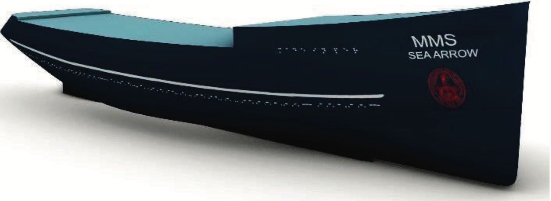
The design of the MMS ship with SEA-Arrow bow was developed following the same principles as the SEA-Arrow bow developed by the Japanese. The model has a straight bow drawn from the most extreme point of the bow of the original bulbous model, which generates a longer waterline length, but maintaining its displacement in the maximum load condition. The study vessel is shown in Fig. 1.
Fig. 1. Isometric view of MMS SEA Arrow ship.
The MMS SEA Arrow model has a length of 44.7 m, which works with a draft of 4.5 m, resulting in a waterline length of 44.5 m. The main characteristics of the MMS SEA Arrow model are described in Table 1.
Table 1. Geometric characteristics of the fuel rod [1].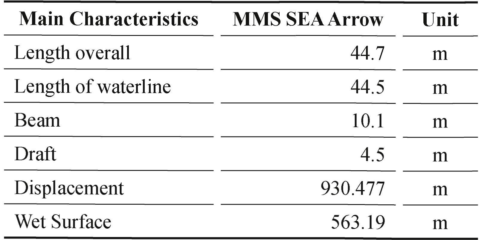
The MMS SEA Arrow model is analyzed by means of CFD (Computational Fluid Dynamics) to determine the drag generated when the vessel moves at a certain speed.
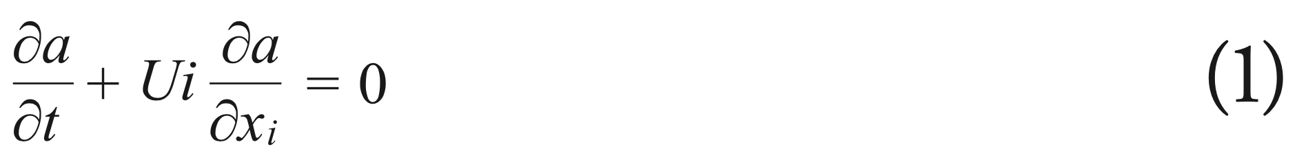
For the development of the CFD, the domain is discretized by means of a mesh, on which it will be analyzed by means of the volume of fluid (VOF) method, which is the most appropriate to simulate the interactions of air and water in the free surface, being able to measure the volume fractions in each cell. The volume fraction is governed by the following equation:
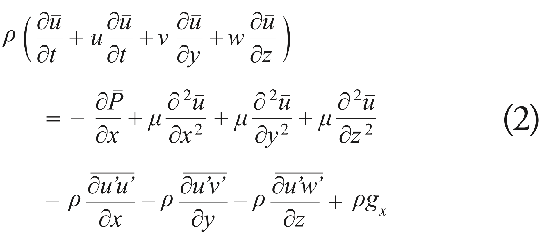
CFD is solved using the R ANS (Reynolds Average Navier- Stockes) equations, which use average velocities for a given time period instead of instantaneous values to describe the flow, which requires less computational resources compared to DNS (Direct Numerical Simulation). Its X component can be defined as:
To determine the drag force in a ship it is necessary to describe the turbulent viscosity in the RANS equations, for which turbulence models are employed, which use additional transport equations to describe the turbulent viscosity, allowing the turbulent velocity and length scales to be described independently. For the present investigation it has been decided to use the k-ε turbulence model, which allows to consider flow history effects such as convection and diffusion of turbulent energy.
To perform the CFD analysis, the conditions of a hydrodynamic test channel are simulated using the recommendations given by the ITTC (International Towing Tank Conference). Fig. 2 shows the dimensions that the computational domain should have so that the waves reflected on the walls do not intervene in the calculation of the resistance.
Fig. 2 Dimensions that the computational domain.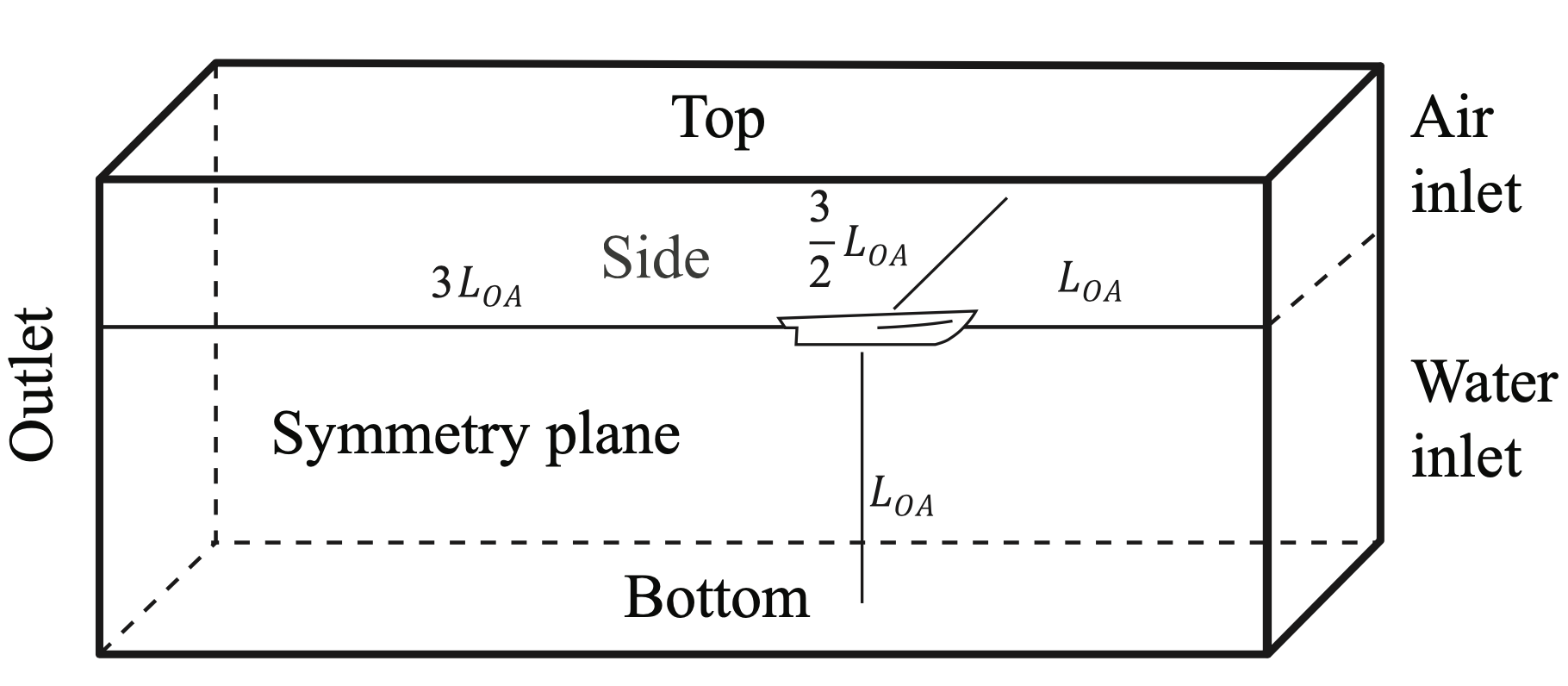
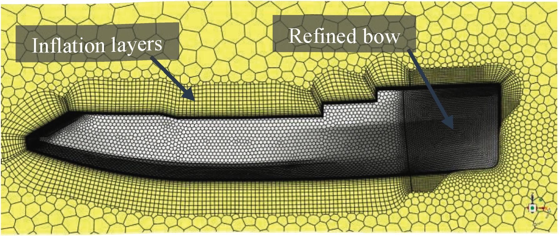
For the discretization of the domain, the Ansys environment was used to take advantage of its tools to generate the mesh. A meshing with a higher density of elements in regions of interest was performed to better capture the flow phenomena in the simulation. In addition, prism layers were created on the hull surface to resolve the boundary layer and obtain the shear stresses on the hull surface. The meshing was generated with the Cutcell meshing algorithm, which forms hexahedral elements, which has an approach adapted for a finite volume based solver. Fig. 3 shows an isometric view of the mesh in Ansys software.
Fig. 3 Isometric view of the mesh.
The boundary conditions are applied for the CFD numerical analysis, following the conditions of a towing test tank. Additionally, we work with only half, taking advantage of the symmetry property of the computational domain. Table 2 specifies the parameters that are used in the computational analysis for a specific speed, in the case shown is for 8 knots of speed.
Table 2. Boundary conditions for 8 knots.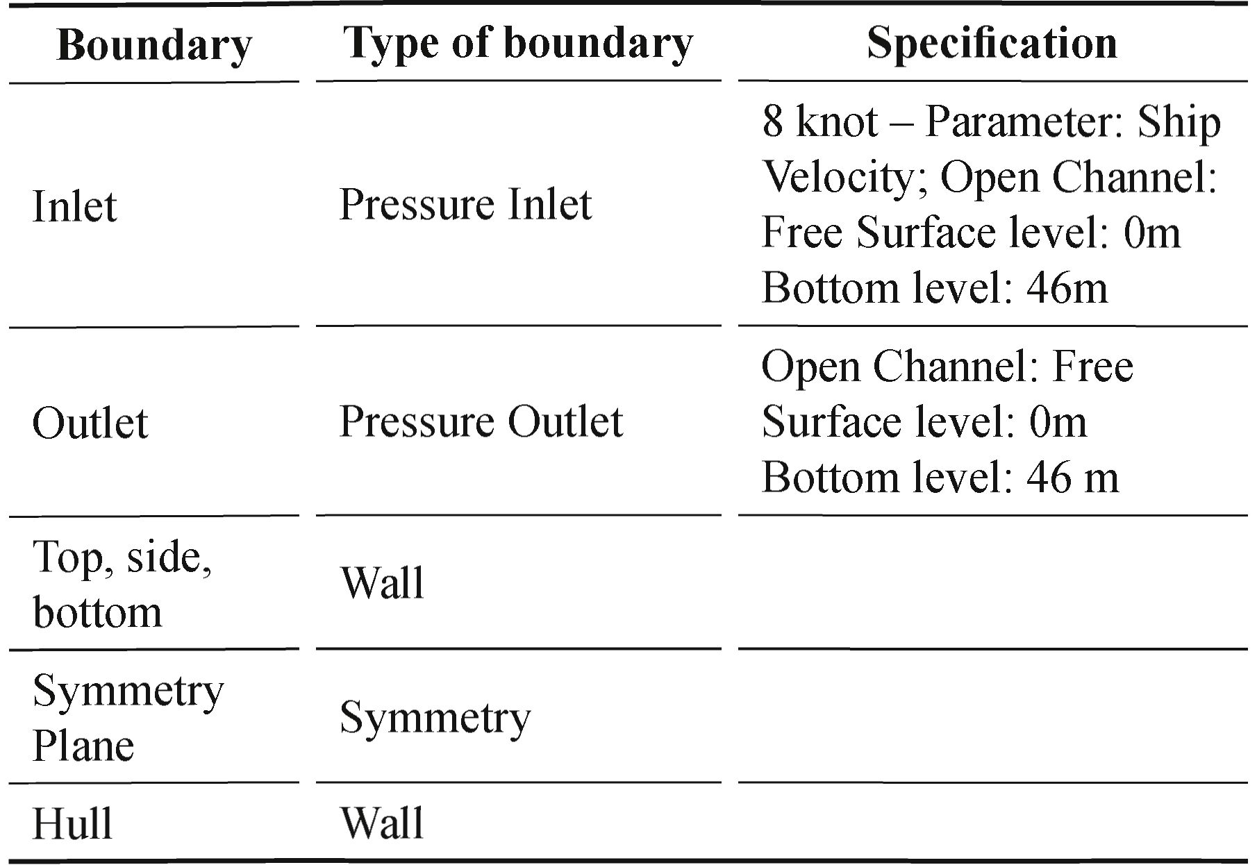
Based on the indicated conditions, the equations are solved in Ansys Fluent
The three-dimensional model of the MMS model was subjected to CFD simulation, using the k-omega (2 eqn) viscosity model with second order solution methods. The simulation was performed to evaluate the drag at 5 velocity points in a range of 8 to 13 knots.
The run was performed with the most relevant operating speeds during the operation with vessels of this type, obtaining the resistance values shown in Table 3, where it is also presented a comparison with the results that can be found by Holtrop's method.
Table 3. Results of the ship's forward resistance MMS.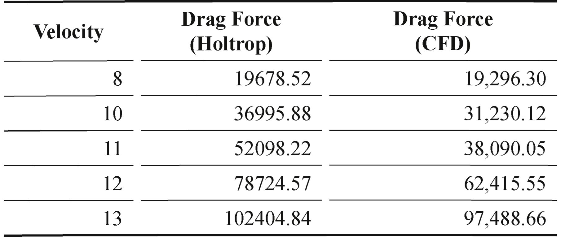
Table 3 reflects the wide margin of error of the Holtrop method, mainly in unusual vessel shapes, such as the SEA-Arrow bow analyzed in the present investigation. It should be noted that the higher the speed, the higher the percentage of error between the two methods.
Fig. 5 shows the trend of the exponentially sloping curve in accordance with the logic of the resistance generated by the vessels.
Fig. 5. Resistance vs. Speed of the MMS model.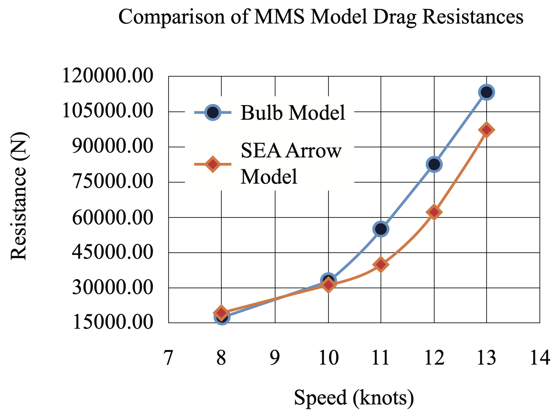
On the other hand, we have the data of the resistance to the advance of the model with bulb, for which we have that, for high speeds, the model with SEA Arrow bow presents resistance values lower by up to 25%, which results in an increase in speed of up to one knot.
It can be said that the resistance up to 11 knots maintains a not very pronounced trend, but from 11 knots on, the curve becomes more exponential. The cruising speed of the boat is approximately between 11 and 12 knots.
From the total resistance values, it can be broken down into frictional resistance and resistance due to wave formation. Fig. 6 shows the percentage of the frictional resistance and wave formation values with respect to the total resistance represented by 100%.
Fig. 6. Results of the ship's forward resistance MMS.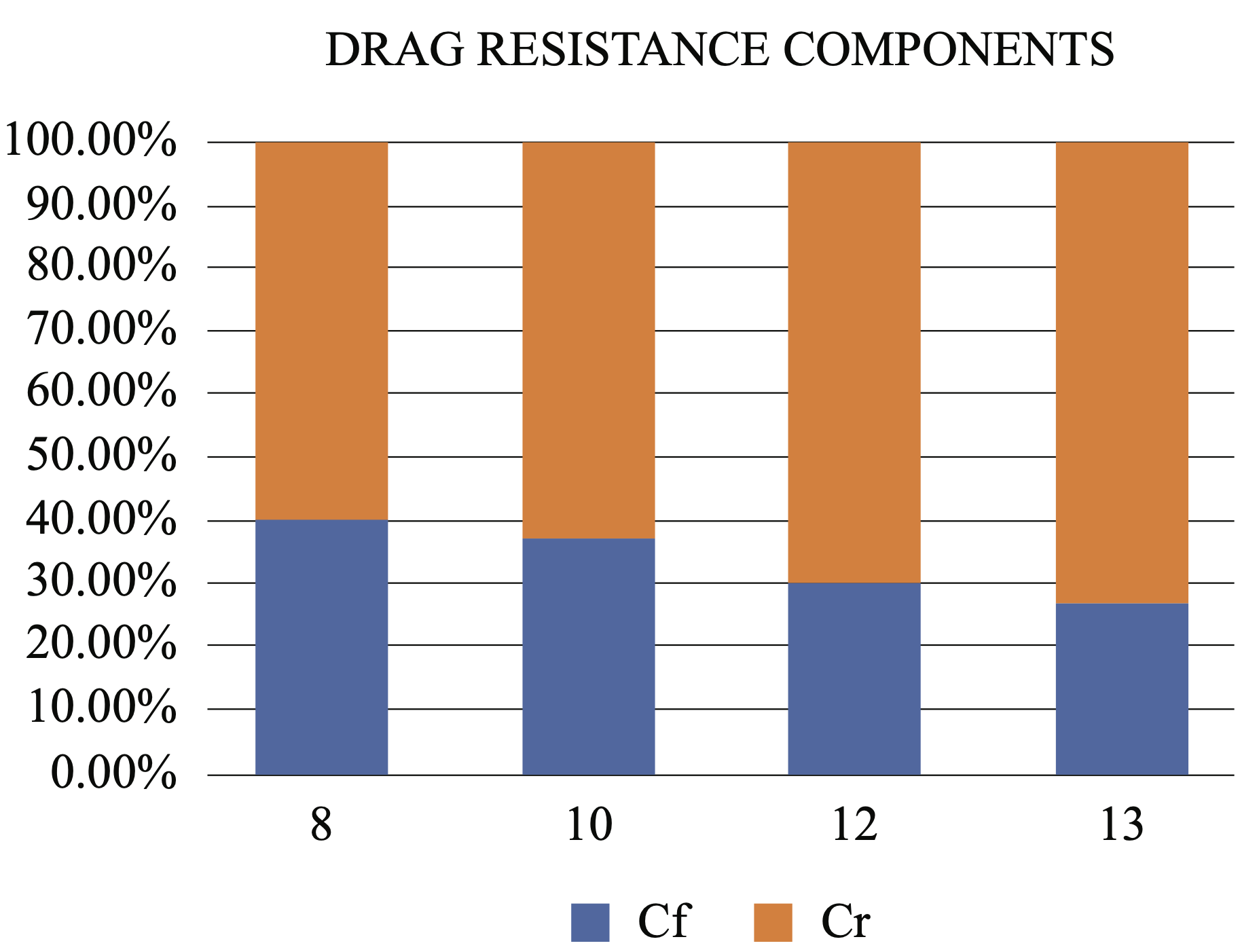
Likewise, Fig. 7 shows the waves generated by the original vessel with bow bulb at a speed of 12 kn.
Fig. 7. Wave profile generated by model with bow bulb.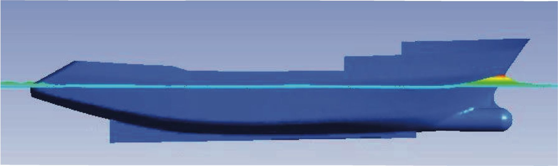
In this figure, the first wave shows a high slope and a fast behavior that finally generates more waves. The opposite case is shown in Fig. 8, where the SEA-Arrow bow has a first wave with a much more subdued and delayed slope, which generates a smaller amount of waves than the bulbous bow.
Fig. 8. Wave profile generated by the SEA Arrow bow model.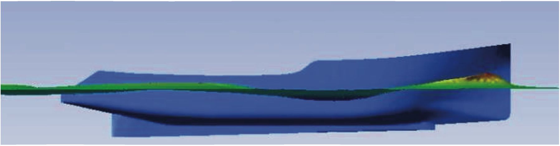
For the correct simulation of the phenomenon, the k-ε turbulence model was used, which satisfied the criteria to validate the simulation.
For the meshing of the vessels, the important parameters such as the size of the elements in the different regions, the layer of prisms around the hull surface were calculated complying with the recommendations given by the ITTC for these simulations.
The Holtrop empirical method presents an error in theresults of the ship resistance that varies between 8 and 35%.
ANSYS Fluent software was used to simulate these hulls of typical Peruvian vessels with the SEA ARROW bow to corroborate the reduction in drag, obtaining reductions of up to 25%.
To thank the National University of Engineering, for providing excellent teaching to its students, in order to apply their knowledge in the development and innovation of naval technology. In addition, to the DSc. Nain Ramos Alvarez, for the motivation and high-quality contribution, to achieve the advancement of both the naval engineering career, and the National University of Engineering.
Special thanks to the institute for development and research in naval engineering of the Faculty of Mechanical Engineering (IDIINFIM) of the National Engineering University (UNI), for allowing the use of its technological resources for the development of the paper.
[1] D. R LINDA TEGEHALL. «Prediction of High-Speed Planing Hull Resistance and Running Attitude», Gothenburg, 2015.
[2] GALDOZ LINDAO, Heinz Bill, “Estudio de la eficiencia Hidrodinámica de un casco con proa tipo X-Bow por modelamiento de dinámica computacional de fluidos, para embarcación pesquera típica peruana”, Tesis de Grado (2019), Universidad Nacional de Ingeniería. Perú.
[3] H. K. VERSTEEGAND W. MALALASEKERA. «An Introduction to Computational Fluid Dynamics», second edition. PEARSON, Essex, England., 2007.
[4] HASSAN MOHAMED, HUSSIEN. X-bow Design for ship Energy Saving (2017). Tesis para el grado de Maestría en Ciencias en Ingeniería, Port Said University, Egipto, 2017.
[5] HELLSTEN ANTTI. “New two-equation turbulence model for aerody-namics applications” (2004). Helsinki University of Technology. Laboratory of Aerodynamics. Finland (2004).
[6] J. B. I CASADEMONT, «Estudio Hidrodinámico po rCFD del casco de una lancha motora», Facultat de Náutica de Barcelona, UPC, Barcelona, jun. 2014.
[7] LIMAY JIMÉNEZ, EDUARDO. Diseño numérico- experimental de un bulbo de proa para una embarcación pesquera tipo cerco (2010). Tesis para optar el título profesional de ingeniero naval, Universidad Nacional de Ingeniería (2010).
[8] MAESTRE, FRANCISCO. Resistencia al Avance del buque [online]. Cumaná, Venezuela. Publicado en marzo, 2013. Disponible en Slideshare: https://www.slideshare.net/franciscomaestre/resistencia-al-avance-del-buque
[9] H.M. HUIJSMANS, J.A. KEUNING, M.J.B.M. POURQUIE AND M.I. GERRITSMA. «Application of the Computational Fluid Dynamics Solver FLUENT to Keels of Sailing Yachts», 2010
[10] RICHMOND, GUSTAVO. “Modelos de turbulencia introductorio” (2019). Research Gate. Costa Rican Institute of Technology (ITCR).
[11] RUMSEY, CHRISTOPHER. Turbulence modeling verification and validation (2014). National Aeronautics and Space Administration (NASA). Disponible en: http://ntrs.nasa.gov/archive/nasa/casi.ntrs.nasa.gov/20140003976.pdf
[12] WATSON, and DAVID, G.M., "Practical ship design"", Gulf Professional Publishing, 2002.
[13] YU WON, JIN. LEE MIN, CHEOL. LEE, INWON. CHOI EUN, JUNG. “Bow hull-form optimization in waves of a 66,000 DWT bulk carrier” (2017). International Journal of Naval Architecture and Ocean Engineering. Department of Naval Architecture and Ocean Engineering, Pusan National University, Busan, South Korea.
[14] Damen takes a Bow [online]. Recuperado de: https://archive.damen.com/en/innovation/some-key-projects/sea-axe-design
[15] Ecuación de continuidad [online]. Recuperado de: http://educativa.catedu.es/44700l65/aula/archivos/repositorio/4750/4918/html/22_ecuacin_de_continuidad.html