Ship Science & Technology - Vol. 15 - n.° 29 - (45-57) July 2021 - Cartagena (Colombia)
DOI: https://doi.org/10.25043/19098642.220
Jaime Pérez-Martinez1
Rodrigo Pérez Fernández2
1 Universidad Politécnica de Madrid, Spain. Royal Institution of Naval Architects, UK. Email: jmartinez@rina.org.uk Ph.D. is professor in several subjects at the Marine Engineering School of the Technical University of Madrid. He is also the Global Navy Sales Manager at SIEMENS Digital Industries Software.
2Universidad Politécnica de Madrid, Spain. Email: rodrigo.perez.fernadez@upm.es MSc. holds the current position of Technical Manager at the Royal Institution of Naval Architects. He is currently pursuing his PhD at the Marine Engineering School of the Technical University of Madrid.
Date Received: April 17th 2021 - Fecha de recepción: 17 de abril del 2021
Date Accepted: July 15th 2021 - Fecha de aceptación: 15 de julio del 2021
In the naval design process, there is still no consensus on the use of 3D CAD (Computer Aided Design) systems in the early stages of design. However, the integration capability of different modules is currently making their incorporation in the initial stages more appealing. The objective of this paper is to study the early stages of design as part of the whole process and to demonstrate the convenience of using a single 3D tool during the whole project. Therefore, its impact on the whole design process will be analysed by considering the basic and early design capabilities of current CAD systems, reviewing how the main naval architecture and marine engineering demands match the features and what is the solution provided by the CAD for each case. The methodology presented offers advantages from a technical, economic and time point of view.
Key words: Ship design, CAD, NURBS, topological model, integration, hydrostatics, structures.
En el proceso de diseño naval no existe aún consenso referente al empleo de los sistemas CAD (Computer Aided Design) en 3D en las primeras etapas del diseño. No obstante, la capacidad de integración de diferentes módulos en la actualidad está haciendo más atractiva su incorporación en las fases iniciales. El presente trabajo tiene como objetivo estudiar las primeras etapas del diseño como parte de todo el proceso y demostrar la conveniencia de utilizar una sola herramienta 3D durante la totalidad del proyecto. Por lo tanto, se analizará su impacto en todo el proceso de diseño considerando las capacidades de diseño básicas y tempranas de los sistemas CAD actuales, revisando cómo coinciden las principales demandas de los ingenieros navales con las características aportadas por el CAD y cuál es la solución proporcionada para cada caso. La metodología presentada ofrece ventajas desde un punto de vista técnico, económico y de tiempo.
Palabras claves: Diseño naval, CAD, NURBS, modelo topológico, integración, hidrostática, estructuras
There are several fields in which CAD (Computer Aided Design) systems could be further developed in the near future. However, the focus of this paper is on the functionalities that are currently being improved. E.g. in the fairing of hull shapes or the global modelling of shapes, they could transform complex surfaces with excellent results, reduced interaction, high precision and complete control. These techniques drastically shorten the design time from days to minutes with excellent results (Pérez & Alonso, 2014).
Another area of improvement concerns one of the most time-consuming tasks in equipment design, the routing of pipes, HVAC (Heat Ventilation Air Conditioning) ducts and cable trays. Automatic routing options minimise this time, but without reducing the robustness of the design there are automatic routing algorithms which provide simple solutions with material optimisation. But the issue is not only to consider existing elements for future routing, but also to prioritise and eventually perform automatic modifications of existing elements as a consequence of future additions. The complexity of the problem explains why there are still no completely satisfactory solutions for automatic routing. However, the current solutions provided by CAD systems solve partial problems and already offer significant support.
Ship design is commonly split into different stages, in most of the cases developed by different agents. As a consequence, tools used for these stages are traditionally different and provide solution only to their particular problems.
At the same time, hard competitiveness in shipbuilding, and subsequent shortening of delivery times and optimization of designs, produce the overlapping of the different design stages, even forcing to follow an iterative and integrated design process. This implies therefore the convenience of using a single tool instead of several ones.
In recent years, improvements have focus the attention in combining basic and detail designs, creating a single 3D model able to obtain classification and production drawings in the most automatic possible way (Alonso et al., 2013). But further improvements are still ahead: to extend the use of this 3D model to the earliest stages of the design, (hull forms definition, naval architectural calculations, definition of compartments, arrangement of main equipment...) thus allowing basic and detail design to take advantage of it.
Changes in shipbuilding industry, consequence of the objective of reducing costs and delivery time but maintaining and even improving quality, have produced changes in all aspects: construction process, project management process and design process. Although changes in any of these processes a ffect the rest, as all of them are interrelated in the common objective of building the ship better, faster and cheaper, it actually happens that the design process is the one mostly a ffected by the others. For instance, the needs for building optimization had as a consequence the creation of the building strategy concept and the necessity to provide with interim product drawings. Also, the convenience of lowering costs by subcontracting tasks are pushing towards the normalization of collaborative design and the remote engineering in every stage.
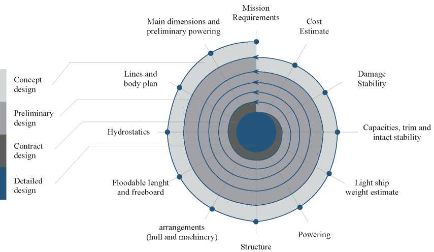
Traditionally, the design process has been conceived as a set of stages, each with its own objectives and scope of supply, performed in a sequential way but represented in a spiral format: concept (preliminary) design, basic (class) design, and detail design. These stages were performed sequentially, starting each once the previous one was finished and approved (Fig. 1).
Fig. 1 Traditional spiral ship design process chart.
However, changes above mentioned have obliged to abandon the sequential performance of the design stages, overlapping them, requiring to start with one before the previous one has been finished or approved. Even more, in many cases three stages are simultaneously being performed. With this, the spiral chart is converted into a set of concentric circles in which there is not clear the termination of one stage and the start of the next one. This design process, that we can call “integrated design process”, is the one assumed by ship designers as the standard one (Fig. 2).
Fig. 2 Integrated ship design process chart.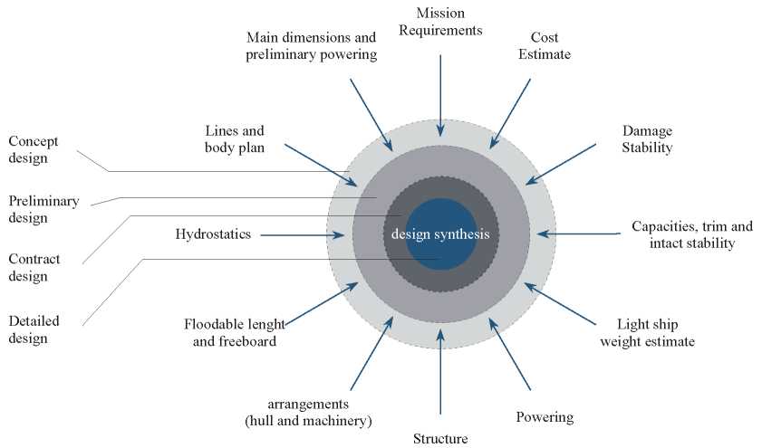
Despite the fact that there is not a clear sequential performance of the different design stages, the impact that each of them has in the overall cost of the project, considering not only the design itself, but also the constructions and even the operational lifecycle of the ship, is different. In such a way, the consequences of decisions taken in earlier stages have much more consequences than decisions taken in later stages. This aspect, together with the fact that in many cases the success or the failure of a decision taken in one design stage is only visible after its completion. Therefore, suggesting the use of the same design tools for all design stages of the process.
Traditionally, 3D CAD systems have been used in the later design stages of the project, manly in detail design. Nowadays, major ship design agents have realised the importance of using a 3D solution for the basic (class) design, allowing to review previous decisions and facilitating the re-work tasks. However, still there is no consensus on the use of 3D CAD systems in earlier stages of the design.
In fact, on top of hull forms, outputs generated during early stages of the design do not require any 3D model, and that is the reason suppliers of software conceived for these stages have not provided enough attention to this. And as a consequence, interaction between early design software and 3D CAD systems has been limited to the interchange of hull forms lines and decks. However, there are concepts defined during early stages of the design that could be fully reused in further stages, with the subsequent savings, and moreover, elements generated during later stages that could feed back early stages and facilitate the revision of previous works and decisions already taken. For this reason, it is very important that the early design solutions (mainly devoted to hull forms definitions and naval architecture calculations) should be the same as the 3D CAD system used in later stages. At least, they should have the possibility of sharing data in an efficient way.
Outputs coming from early design can be grouped in four different concepts:
The key point is to combine these four concepts in the best form to allow that modifications are easily managed and outputs automatically reissued according to them. Moreover, as many of the parameters considered in this stage of the design correspond to estimations, it would be of extreme importance to have the possibility to feed these parameters with actual data coming from a later stage of the design (Fig. 3).
Fig. 3 Early ship design flow.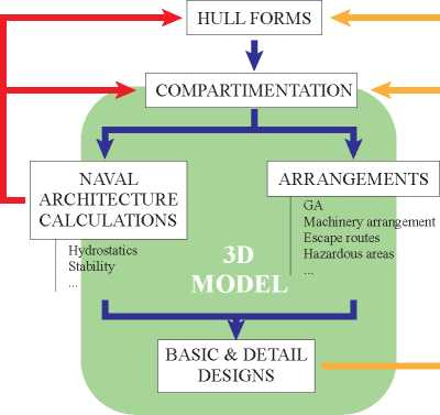
This approach for integrated early ship design has been adopted by some CAD providers and it will be described in the following paragraphs.
The key aspects of a CAD system to allow the use of this approach are the following:
At the end of the process, the results in terms on quality and time are greatly improved.
The proposed solution is based on a 3D ship product model, see an example on figure 5, in which the geometry and the attributes of the elements of the ship are stored. The model is built as an essential part of the engineering work. It can be used to visualize the progress at all stages and can be exploited to obtain information for material procurement and production. The main characteristics of the ship product model are discussed in the following paragraphs.
Building an early 3D model allows to improve the design process of the ship and to study different design alternatives in shorter periods of time, which reduces both delivery schedule and cost.
As a result, it is possible to reach a better performance when developing the design and, at the same time, to obtain a product of high quality in a very competitive way. An optimal CAD solution should be based on the integration of all the design stages and disciplines by means of a single database. Thus, allowing for the implementation of collaborative engineering and ensuring information integrity.
The use of a topological model instead of a geometrical model, facilitates its definition, and allows for a quick study of different design alternatives. Furthermore, it simplifies the implementation of modifications, which are very common in the early design stages. The main advantage of the topological definition, where geometrical data are not stored but calculated on-line, is that changes in the main hull surfaces are automatically incorporated in the modified elements, just by reprocessing them. In addition, the topological definition allows the existence of powerful copy commands making thus the definition far more efficient than working only with geometry. Another benefit of the topological model is the size of the information stored in the database, which is significantly lower than for geometrical models.
The key aspect of the design process is the definition of a single ship 3D model, accessible for several designers working concurrently, to be used in all stages of the design. While the project is progressing, the level of detail is increasing and the different parts of the model are subdivided by means of a progressive top-down definition. The solution implemented should include tools to facilitate the direct transition from basic to detailed design (Lee et al., 2013), by means of simple operations that include block splitting, the assignment of parts to blocks and the completion of the model with attributes for the manufacturing phase (Pérez & Lee, 2014).
Fig. 4 LPD Surface definition using NURBS.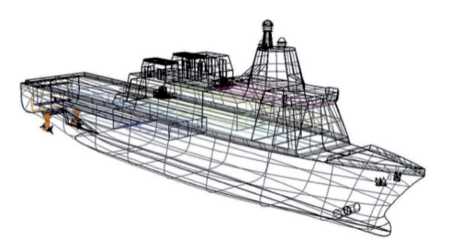
Some CAD systems are developed with the capabilities to define a surface model based on NURBS (Non-uniform rational B-spline) formulation. The surface model is one of the most important components of the ship model, especially for basic design and detail design. NURBS is considered the most generic formulation to represent a surface in Computer Aided Geometric Design and in nearly all cases is very suitable for the definition of hull forms. An unlimited number of NURBS patches can be defined, and this collection of patches can then be used to define the hull forms file. Patches can be edited, and a complete set of geometric transformations is provided (Pérez & Toman, 2014a).
In order to complete a production quality model definition, they may include sophisticated tools such as sewing patches to patches and to curves, fitting curves and patches and management of patches tangent condition among others. Also they may include the construction frame system as well as the deck and bulkhead surfaces of the Ship, which in turn benefits the hull forms information. The next step after the hull forms, the decks and the bulkheads are defined, is the definition and management of the compartments of the ship in a fast and flexible way. Based on a hierarchical tree structure, theoretical surfaces, compartments and versions of them need to be defined and easily managed to offer different alternatives to the compartment arrangement of the project. In a 3D environment and using as initial information the main surfaces of the ship, any ship compartment is easily defined by means of subspaces, that are the geometrical representation of the compartments. These sub-spaces are created using different geometric operations. Combination of different subspaces may define complex geometry. Negative spaces and appendages can be defined, such as bow-thrusters or rudders (Fig. 5).
Fig. 5 Compartmentation of a vessel using the CAD/ CAM/CAE system FORAN.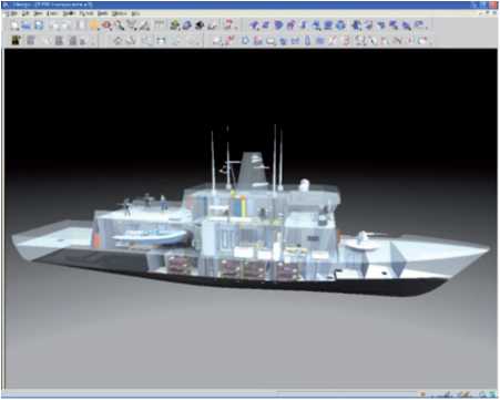
The topological definition of all these elements ensures that any modification to their limits is automatically applied to the compartment geometry.
Once the geometry has been determined, the Hydrostatics can be evaluated, which consist of the calculation of:
The hydrostatic values can be obtained for different drafts, for different trim angles and for different densities of seawater. Furthermore, some systems give the option to obtain the numerical output in sagging or hogging situations.
The cross curves of stability can be obtained for different trim angles, heel angles and displacements introduced as data by the user or for standard values. Calculations are carried out with the ship in still water or in a trochoidal or sinusoidal wave. Hull openings are considered in the calculations.
The calculation of the regulatory freeboard is to be carried out according to the Load Lines Convention of 1966 and its latest updates.
Main aspects included under the Intact Stability are:
Distribution of lightship weight is preliminary calculated by estimate or definition. It is important to remark that the aim of this job is not the calculation of lightship weight, which must always be an input data, but the lightship weight distribution. The more detailed the 3D model of the ship is being built, the more accurate should be the calculation, as many of the weights could be directly considered instead of being estimated.
Following types of calculations can be performed, with numerical and graphical outputs:
International and national stability regulations, as well as specific criteria for special vessels according to different CCSS and any other specific criteria defined by the user are normally checked.
Longitudinal strength calculations are carried out with the ship in still water or in a trochoidal or sinusoidal wave. Shearing forces and bending moment curves, as well as the weights and buoyancy curves, distributed by construction frames, are obtained. Shearing and bending deflections are part of the calculations completed.
Different types of cargoes are handled:
After the process of a load condition, weight, coordinates of centre of gravity (total and itemized), equilibrium waterplane and even keel flotation, static and dynamic stability tables, checking of the stability, shear forces, bending moments, deflections and other relevant data is obtained and verified.
The purpose of the Damage Stability is the calculation of flooding conditions (defined as combinations of initial situations and damage conditions) and damage stability according to the deterministic and probabilistic methods, depending on the type of ship.
For deterministic method, input data for the calculation is an initial condition given by: previously defined loading condition, fore and after drafts and height of centre of gravity, and a set of drafts (for maximum KG's calculation). The damage situation is given by the damaged compartment, including the corresponding permeability and, in case of liquids, filling percentage and density. Information such as the equilibrium waterplane, compliance with corresponding international and national stability criteria, centre of buoyancy position and location of the hull openings after flooding can be obtained, together with graphic representations of the flooded compartments. The equilibrium waterplane and the static and dynamic stability curves are also obtained for the intermediate stages of flooding. It is also possible to calculate maximum KG's, and water on deck considering the residual freeboard and damage stability.
For probabilistic method, the Attained Subdivision Index 'A' and the Required Index 'R' for cargo and passenger ships, according to latest regulations for cargo and passenger vessels are calculated. For the first steps of the project, using the hull forms and the main deck, it is possible to define a geometric subdivision and to obtain automatically a generation of the spaces of the ship. This option allows the definition of the final compartmentation of the ship according to regulations. In advanced steps of the design, when additionally spaces and loading conditions are provided, the module takes into account the intact stability conditions and associates the spaces to the geometric subdivision defined in the module. During the process, it is possible to define a subdivision by selecting a set of sections (transversal, longitudinal and horizontal) and intact stability conditions. The module calculates all the indexes (compartments and groups) and their contribution to the evaluation of the 'A' Index.
Several tasks are performed under Powering prediction: calculation of towing resistance by means of the most modern prediction methods, propeller selection, powering, rudder geometry and manoeuvrability characteristics, propeller geometry and schematic stern profile definition.
The calculation of the power-speed curves requires the main particulars of the ship as input data in the calculation process. The ship data is taken through the integration with the hull form definition information, although manual data input is also available.
After defining the range of speeds, the designer may select the power prediction method that best fits the ship type. Different power prediction methods can be used for a fast comparison of results and for different types of ships.
Different alternatives for the propeller selection may be provided: i.e. Wageningen B Series, Propellers in Nozzle, Gawn-Burril and Newton-Rader. With the required data listed below:
The output information includes the main features of the propeller, power-speed curves (at fractional draughts if required), prediction for service and trial condition (even for trawl condition in case of trawler ships) and open-water propeller diagrams.
Once the hull forms, decks, bulkheads and other surfaces are created, it is possible to commence with the definition of the hull structure of the ship: major openings in all surfaces, scantling of the main surfaces for plates and profiles, as well as the main structural elements (floors, web frames, girders, stringers, etc.). The definition is usually based in the frame and longitudinal systems which allows a full recalculation of the model in case of changes in the spacing between elements.
In early stages, plates and profiles are created as objects representing zones of a surface with common scantling properties. Therefore, the size of the objects is not consistent with the manufacturability, which will be considered in later stages of the design. Other properties like the continuity and watertightness attributes of surfaces or parts of them can be defined at any time. Designers would normally follow the same rules as when working in 2D, which means to start with the definition of the continuous elements because this will allow the automatic splitting of the non-continuous elements. However, that sequence could be modified by creating both plates and profiles at different design stages.
Fig. 6 Definition of structural main elements.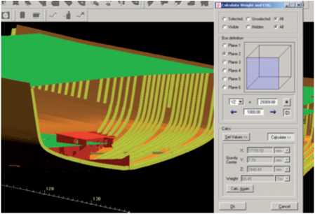
The assembly break down to unit or block is optional at this stage, and the level of detail of the 3D model is the one required by the classification drawings, with respect to the type of parts included (brackets, face bars, clips, collars, etc.) as well as to other characteristics (profile end cuts, scallops, notches, etc).
Due to the topological definition of all elements, any changes in a previous stage does not require the repetition of the work already done: all elements, calculations and parts are automatically updated to the new condition, with the subsequent savings in time and man hours. This also supports the designer when prototyping new ships and the optimisation phases.
The 3D curved surfaces context allows the definition of plates, profiles and holes. Work division is made by using the surface and zone concepts, which allows the multi-user access to any surface. A general zone may be used to contain the entities common to several zones. The following type of profiles can be defined:
Profile definition is mainly based on topological references to already existing structural elements, as well as to auxiliary concepts used in the early stage of the design (longitudinal spacing, frame system, other profiles, etc). Then the user assigns different attributes such as material, scantling and web and thickness orientation. These basic attributes can be completed by adding constructive attributes (parametric web, flange end cuts, etc) at any time of the design process . The profiles can be split up in profile parts later, when the transition from basic to detail design is performed. When profiles cross other profiles the CAD systems generally generate the necessary cut-outs and scallops. Those profiles including flat, curved and twisted are represented as solids. Then web, flange and the corresponding end cuts are displayed depending on the configuration chosen.
Due to the intensive use of topology, the definition of the shell and deck plating can start in the early stages of the design, even with a preliminary definition of the hull and decks. In this regard, the basic concepts are:
Flat and curved plates are represented as solids (including thickness) and the information for plate pre-development is automatically generated allowing thus an early material take-off list. The internal structure context is based on the same high performance topological and visualization environment of the curved surfaces, but applied to a section lying on a plane. This environment provides a set of advanced functions for the easy definition and modification of plates (flat, flanged and corrugated), straight and curved stiffeners, holes, face bars, standard plates, on and off plane brackets, collars and others (Fig. 7).
Fig. 7 Structure basic 3D model of a patrol vessel.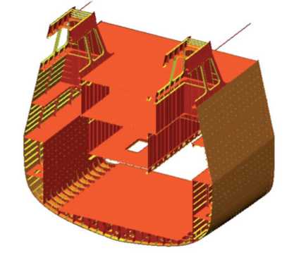
In order to facilitate the operations, it is possible to have several sections in memory, like copy or multiple editions of elements in different sections. The work division is made by using the section, structural element and zone concepts, which allows multi-user access to any section.
One of the most relevant aspects during the basic engineering of a ship is the structural analysis by means of the application of FEM. In practice, it is a laborious task that requires the preparation of a suitable model for calculation, meshing, the application of loads and constraints, processing, post-processing and analysis of the results.
Most of the finite element tools include standard formats for the direct import of 3D CAD models, but they fail when these models come from the shipbuilding industry due to the complexity of the ship models. The effort required in the manual simplification of the model is such that it is more efficient to repeat the model with a calculation-oriented approach, which slows down the analysis process dramatically.
The use of a ship model already created in a 3D CAD for FEM analysis would optimise the design performance in the early stages (Pérez & Toman, 2014b). A simplified ship model to be exported is preferable, and can be made possible leveraging its topological characteristics. Functional algorithms allow for the creation of an intelligent model, simplifying, filtering and deleting unnecessary data to guarantee the quality of the model transferred.
Among other functionalities, there are decisions to be made regarding the model being imported:
With the information coming from the hull forms, decks, bulkheads and compartmentation, it is enough to start the basic design of machinery and outfitting, creating the outfitting 3D model. Although it is highly recommended to have the hull structure of the ship for reference purposes, this is not mandatory, and the designer can take enough decisions to consider this as a virtual one. When working in the 3D model, the user must check that there are not interferences even with virtual elements. In such a way the system will guarantee that the design is collision-free from the very beginning.
Equipment lay-out is an essential aspect, that compromises even the compartmentation of the ship as all rooms should be provided with enough space to guarantee the correct performance and handling of equipment inside. The sooner the equipment are positioned, the more advantages can be obtained from it. Normally the equipment in the actual models are unknown at this early stage of the design. However, it is possible to start with the positioning of rough models representing the equipment, and to gradually refine them as soon as more reliable information is received. The update of the model data in the corresponding library will automatically produce the update of the equipment already positioned. Equipment models are stored in libraries that can be created for a particular project or can be imported from other projects or from catalogues from suppliers. Models can incorporate, in separate layers, all information regarding necessary maintenance spaces in order to take into consideration from the very beginning of the design process all needs for dismantling, repair and any future update during the ship's life cycle.
Equipment positioning is done with reference to existing structure (plates, profiles,..), but also it can be done with reference to theoretical lines and surfaces of the ship (hull forms, decks, bulkheads and frames). In such a way, equipment positioning can be started just upon having the hull forms data. Any modification in reference elements automatically updates the position of the equipment. Positioning can be done in a topological way, so any modification in referenced objects automatically produces the update of the position (Fig. 8).
Fig. 8 Equipment lay-out referenced to theoretical lines.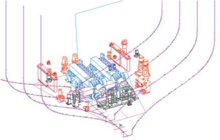
The objective of the P&I diagrams is to define ship system diagrams, including the associated logic of connecting equipment and fittings. Those diagrams include the following information:
The sooner the diagrams are created, the lesser technological information is available, so it is possible to start defining flow diagrams with almost only graphical information and to complete them gradually as soon as this information being available. Diagrams can be geographical or not, depending on the common practise for each ship system. In case of geographical diagrams, representations of the ship taken form the hull forms, 3D model or any drawing generated from them can be used for reference purposes.
Routing tools provide the functionalities to arrange the equipment, route the distributors (pipelines, ventilation ducts and cable trays as space reservation), generate the auxiliary structures (foundations, gratings, handrails,.), insert the supports (made with the auxiliary structures entities but linked to the distributors) and carry out the spooling of the pipes and ventilation ducts. Also, HVAC calculation can be done regarding to the 3D ventilation ducts existing in the model.
The aim is to create, at the basic design stage, a 3D model with the most complete information as regards distributor lines (supports are included if needed). This 3D product information is made available to other modules for clash detection, reference or generation of drawings and reports during the ship design process (Fig. 9).
Fig. 9 Routing of pipes referenced to theoretical surfaces (decks).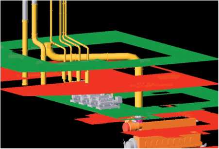
Common features available for this purpose are:
The key point to for any software solution aiming to provide a complete solution for ship design and manufacturing is the capability to offer a smooth transition between the stages of the design avoiding rework and delays. Thus, as a logical continuation of the basic design. For example, providing in the hull structure tools for subdividing and joining plates and profiles, including additional attributes for detail design such as bevelling, construction margins and shrinkage factors, and also for defining parts that are not relevant during the basic design stages. In outfitting, it should be possible to add technological properties and refine equipment, split pipes and ducts, and add fittings (Fig. 10).
Fig. 10 Basic 3D model of a tanker, ready for performing the detail design.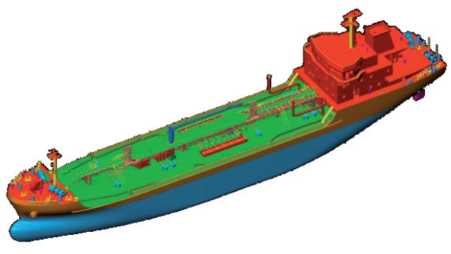
The methodology from the initial to the basic and the detailed design is also the approach from the conceptual and abstract to the concrete and manufacturable. Large conceptual parts useful to analyse, for instance weight and functional behaviour, must be converted into manufacturable parts reusing all the information provided in the conceptual stages and detailing when necessary.
Among others, the benefits of this approach can be summarized as follows:
The CAD system approach discussed in this paper improves design quality, provides higher precision and reduces the risk of inconsistencies.
The rapid evaluation of several design alternatives and the early estimation of materials, weights, welding and painting are additional advantages. Moreover, when efficiently used in conjunction with finite element analysis tools. Finally, it also facilitates the definition of the outfitting (general and critical compartments layouts) and improves the coordination between disciplines. In conclusion, the key points are the simple transition to detail design and the reuse of information.
Fig. 11 3D model of a ship's engine room including outfitting.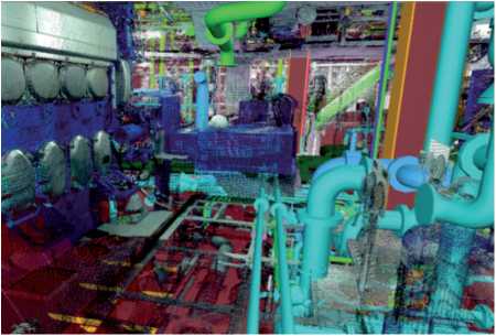
This substantial change in the development of the basic design stage, which is now being required and implemented, is expected to become the routine way of working in the future, particularly when the continuation with the detail design is considered and/or outfitting design is part of the scope of work.
It is well known that most of the costs of a ship are compromised during the early design stages. The proposed solution delivers tangible benefits as it optimizes the process by reducing the time dedicated to design and consequently the cost, and at the same time improving the quality of the design, and therefore the quality of the ship.
ALONSO, F., GONZALEZ, C., PÉREZ, R. (2013). How the use of a next-generation 3D CAD tool in basic design stage leverages to improve the overall warship design and production, Warship 2013: Minor Warship, Bath.
LEE, D.J., CEBOLLERO, A., PÉREZ, R. (2013) New approach to design transition in Korean production environment, ICCAS 2013, Busan, pp.109-118.
PÉREZ, R., ALONSO, V. (2014). The ultimate approach for general arrangement definition, Ship Production Symposium 2014, Houston.
PÉREZ, R.; DOO-JIN L. (2014). An innovative approach for Korean CADres, The Naval Architect, July-August, pp.58-61.
PÉREZ, R.; TOMAN, M. (2014a). An innovative approach for hull surface fairing stages, 13th COMPIT 2014, Redworth, pp.32-40.
PÉREZ, R.; TOMAN, M. (2014b). Tuning CAD tools to fi t naval design requirements, INT-NAM 2014, Istanbul.
PÉREZ, R.; ALONSO, V.; VALDERRAMA, A. (2013). The use of a 3D CAD system for early design in shipbuilding, Ship Production Symposium 2013, Bellevue, pp 545-553.