Ship Science & Technology - Vol. 15 - n.° 29 - (21-35) July 2021 - Cartagena (Colombia)
DOI: https://doi.org/10.25043/19098642.218
David Alvarado 1
Edinson Flores 2
Edwin Paipa 3
1 COTECMAR, División de Diseño e Ingeniería, vía Mamonal km 9. Cartagena, Colombia. Email: dalvarado@cotecmar.com
2 COTECMAR, División de Diseño e Ingeniería, vía Mamonal km 9. Cartagena, Colombia. Email: eflores@cotecmar.com
3 COTECMAR, División de Diseño e Ingeniería, vía Mamonal km 9. Cartagena, Colombia. Email: epaipa@cotecmar.com
Date Received: April 15th, 2021 - Fecha de recepción: 15 de abril del 2021
Date Accepted: July 25th, 2021 - Fecha de aceptación: 25 de julio del 2021
Inland navigation in shallow waters with partially submerged objects and riparian vegetation might represent severe restrictions to patrolling operations of the Colombian Navy. Consequently, there is a need for a riverine combat and reconnaissance boat with the ability to operate in 0.4 m depth shallow waters and which structural arrangement is to be designed according to maritime classification societies and operational requirements of the navy.
The aim of this work is to explain and to validate the 20 knots, 3.8 tons of displacement, 8.6 m length, 2.6 m beam and 0.35 m draft boat scantling by guidelines of the classification societies and hence, improving and validating by direct analysis the hull structural arrangement.
Key words: Scantling, direct analysis, aluminum hulls, riverine combat boats.
En la navegación fluvial, las bajas profundidades, objetos parcialmente sumergidos y la presencia de vegetación representan restricciones para las labores de patrullaje y reconocimiento de la Armada Nacional. Por tal motivo, surge la necesidad de contar con una embarcación con capacidad de operar con un calado mínimo de 0.4 metros y que su arreglo estructural esté diseñado acorde con las recomendaciones de las sociedades clasificadoras y las necesidades operacionales de la Armada nacional.
En el presente trabajo se detalla el escantillonado de un casco en aluminio con 8.6 metros de eslora total, 2.6 metros de manga y 0.35 metros de calado cuyo diseño permite una velocidad de 20 nudos, y un desplazamiento de 3.8 toneladas. Se siguió las recomendaciones establecidas por las sociedades clasificadoras y se realizó una posterior validación y mejoramiento del arreglo estructural por el Método de Elementos Finitos.
Palabras claves: Escantillonado, análisis directo, cascos en aluminio, botes de combate de río.
In military river operations are important the availability of high-speed crafts capable of performing patrolling, tactical offensive and defensive maneuvers and additional tasks related to homeland security and defense in shallow, secluded and hard-to-reach harsh inland waters [1].
The riverine low draft combat boat designed with naval- grade aluminum and 10 m2 polymeric ballistic protection panels on deck, can develop riverine patrolling and reconnaissance operations in shallow depth waters. The technical feature of this boat includes a 15 knots maximum speed, an operative range of 300 km, and the capability to provide tactical fire support.
To carry out the previously explained operations, the design and manufacturing of a low-draft inland waters combat boat is required [2]. Thus, the structural arrangement of the designed boat is intended to maintain a low weight while the security of the crew, the structural integrity of the hull and the boat performance remain preserved.
To ensure the structural integrity of the hull, the scantling was performed according to recommendations and requirements of the classification societies ABS in “Rules for Building and Classing, High- Speed Craft; Hull Construction and Equipment” [3] and ISO 12215 “Small craft - Hull construction and scantlings - Part 5: Design pressures for monohulls, design stresses, scantlings determination” [4]. Given the structural arrangement obtained, its structural integrity was evaluated and improved by direct analysis in a global model according to “Class Guideline- Finite Element Analysis” by DNV-GL [5].
The hull scantling refers to the assessment of selected plates and stiffeners’ geometrical dimensions according to their mechanical properties, global position, and section modulus. The strength of the hull to environmental and duty external loads depends largely on the structural arrangement and its capability to withstand bending and shear stresses [6]. Scantling leads to an iterative process in which calculations are based on semi-empirical relations, Euler-Bernoulli beam theory, and principles of linear-elastic mechanics. First, the hull girder strength was assessed according to cross-section inertial properties followed by local calculation of plates thickness and cross-section of primary and secondary stiffeners. Structures which effect on the structural arrangement are considered local were calculated according to rules calculations [7] [8]. The structure Von Mises stress levels were compared with limit values allowed by the classification societies.
High strength aluminum alloys, in recent decades, have been increasingly applied for the design and construction of high-speed vessels as the size of these vessels has grown and their operation moved to harsher conditions [9]. Aluminum alloys, compared to steel, show advantages such as a better strength/weight ratio and a higher corrosion resistance [8].
In comparison to high-speed crafts manufactured with Glass Fiber Reinforced Plastic (GFRP), aluminum alloys manufactured hulls have a lower weight and a higher toughness against bottom impacts; the bottom plates are prone to dissipate energy as deformation instead of crack propagation [10]. Nevertheless, aluminum alloys show disadvantages such the yield and tensile strength are deeply affected by high-temperature gradients as a consequence of welding procedures [8] [11]. As a result of these procedures, high temperature zones are spotted which consequent expansion and contraction gradients resulted in high residual stresses [12].
It is estimated in scantling calculations a mechanical properties reduction between 50% and 70% depending on the used aluminum alloy [3] [11], on the other hand, some researchers such as Paik et al. [13] and y Collete [14] stated that these mechanical properties reductions might be conservative. Collete [14] in his research has shown that series 5000 aluminum alloys presented, in heat-affected zones, tensile strengths values close to those of not welded aluminum alloy conditions whereas 6000 aluminum alloys series showed a noticeable decrease. The 6000 series alloys are not as corrosion resistant as the 5000 series, but are easier to extrude, making them attractive for producing structural shapes [14]. Additionally, it must be considered that imperfections resulting from welding processes such as the permanent deflection of plates, might imply an 18% decrease in tensile properties and an increase in buckling failures probabilities [7] [15].
Aluminum plates and stiffeners must have a stiffness equivalent to steel counterparts as a design criterion [16]. In this way, the plates of the structure and the respective primary and secondary structural reinforcements are to be designed in such a way their mechanical strength is high enough to prevent crack initiation due to wave pressures on the hull [17]. The vessel, during its lifespan, will be subjected to loads as a function of contact time such as collisions, slamming and grounding. Due to light materials used in their construction, highspeed crafts subjected to slamming phenomenon are prone to present high elastic deformations in the bow by impacts with the water surface [18].
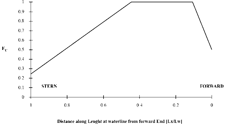
For small crafts, under riverine conditions, classification societies’ rules dictate a design wave height of 0.5 m and a design speed of 20 knots speed to calculate vertical accelerations in the hull. Next, from plate pressures, spacing between stiffeners and selected materials properties, it can be selected the hull's plates thickness. The hull girder amidship section modulus can be determined with cross-section properties of longitudinal plates and stiffeners which length is superior to 60% of scantling length. The resulting structural arrangement will be detailed in the methodology section and scantling calculations can be revised in [3] [4].
The structural arrangement assessment from rules and guidelines of the classification societies, which calculations are generally of semi-empirical nature and also are calibrated to secure the lifespan expected, allow a simplified approach of complex structural problems [7]. However, classification societies’ rules might imply suppositions that can only be used with certain limits, then, those calculations might not fit well to the studied arrangement and the obtained structural arrangement could have a more effective and lighter alternative. Therefore, in recent decades, direct analysis by the finite element method has increased its importance in the shipbuilding industry [19].
Hence, the main aim of this work is to evaluate, by classification societies semi-empirical rules calculations and direct analysis by finite element method, the strength of the obtained structural arrangement of this combat boat. Additionally, a modal analysis was performed to estimate the resonance frequencies of structural elements and a linear buckling analysis was also carried out to dismiss the possibility of the hull failure by compressive loads.
With the present methodology it was detailed the obtained structural arrangement, the rules and guidelines applied and the followed procedure to prepare the computational modeling.
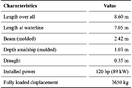
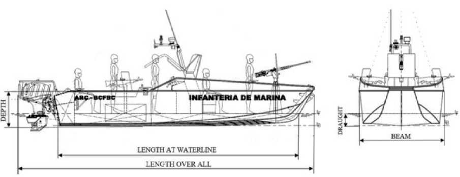
The principal characteristics of the designed combat boat are summarized in the next table [see table 1]. The bottom structure of the vessel consists of a 12 mm of thickness AW 5083 H321 keel, four AW 6082 -T6 longitudinal bulb stiffeners, and two 4 mm thickness side girders. These elements are spacing 250 mm whereas frames have a 750 mm spacing, except for frames in the bow, and a 6 mm thickness AW 5083 H321 bottom plate [see Fig 1].
Table 1. Riverine combat boat principal characteristics.
The sides’ structure consists of AW 6082-T6 flatbar longitudinals; whose purpose is to provide the required stiffness to 4 mm thickness AW 5083 H321 side plates. These plates are to be vertically supported by 4mm thickness AW 5083 H321 frames [see Fig. 2]. Four of these frames are 4 mm thickness watertight bulkheads. The deck is composed of a 4 mm thickness AW 5083 H321 plate and five type flat-bar longitudinal stiffeners. This deck is transversally supported by ‘L’ profiles deck beams and bulkheads and longitudinally supported by two side girders. The transom is composed of 10 mm thickness plates between the two side girders and 6 mm thickness AW 5083 H321 plates in the rest of the hull given the force reactions of the assembled outboard motors.
Fig. 2. Typical frame.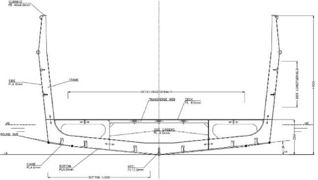
The followed scantling rules [3] [4] are based on hull girder strength and local strength requirements. Then, from principal dimensions of the boat, the proposed structural arrangement and design pressures, scantling of plates and stiffeners are calculated [see Fig. 3].
Fig. 3. Scantling methodology.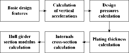
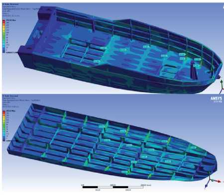
Global modeling of the boat and the subsequent finite element method analysis are explained in detail in this section. This analysis implies local refinements of relevant structural details. Furthermore, the analysis is subjected to plain stress and linear-elastic mechanics simplifications.
The whole structural arrangement was modeled including examples of critical connection details. Shell modeling was carried out by using ANSYS SpaceClaim 2019 software [see Fig. 4]. Bonded contacts were used among structural elements given their welded connections.
Fig. 4. Global modelling using Ansys SpaceClaim.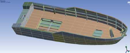
SHELL181 elements were used for meshing. This four-node element with six degrees of freedom at each node is suitable for analyzing thin to moderately thick shell structures [see Fig. 5]. After a convergence test, a 20 mm meshing element size was used. For structural details element size, up to 4 mm were set. The shell geometry is represented by 4 Node Linear Quadrilateral elements; the degenerate 4 Node Linear Triangular option was only used as filler in mesh generation [20].
Fig. 5. Meshed model.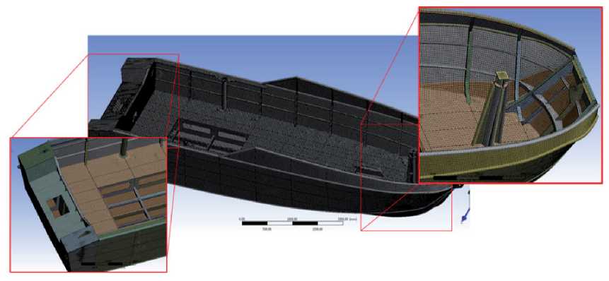
The boundary conditions for the global structural model should reflect simple supports that will avoid built-in stresses so the reaction forces in the boundaries are to be minimized [5]. ANSYS Inertia relief option allows to balance the force differences on the supports creating a state of static equilibrium. Two of these fixation points were applied at transom intersecting the main deck at port and starboard, and the last one, in the bow centerline intersecting waterline.
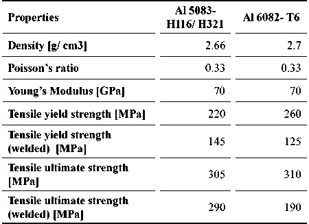
5083- H116/ H321 aluminum alloy mechanical properties were assigned to plates whereas aluminum alloy 6082 T6 properties were set to stiffeners [see Fig. 6]. The mechanical properties of both aluminum alloys are detailed in the next table [see table 2].
Fig. 6. Plates and stiffeners materials.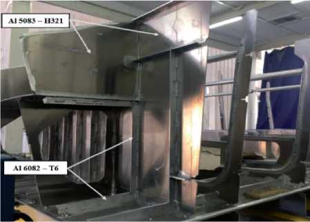
This analysis is completed using the Maximum-Distortion- Energy Criterion in order to assess the structure against failure. This criterion takes both shear and normal stresses into account to develop a combined equivalent stress, σi.
According to this criterion, the structural arrangement will not fail as long as σ i <Sy, where S_y is the tensile yield strength of the material. A class allowable stress factor (FP=0,85) is added in such a way yield strength of the material is reduced [20]. The maximum allowable stress for plates is 123 MPa and 106 MPa for stiffeners specifically in heat-affected zones.
Design pressure calculations from class requirements of both classification societies [3] [4] are detailed in the next table [see table 3]. Due to design pressures calculations are slightly higher in HSC rules of ABS, these values are taken into account in the finite element model load inputs [see Fig. 7].
Table 3. Calculated design pressures.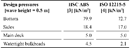
This analysis allows to determinate the inherent dynamic characteristics of a system in forms of natural frequencies. Then modal analysis is used to identify natural frequencies and vibration modes of the structural arrangement. A special emphasis was placed in transom due to the outboard motors effect on the structure; mass and inertial properties of these motors were taken into account. Structural displacement restrictions are maintained for this analysis.
An eigenvalue buckling analysis was performed to ensure no structural elements failures by compressive loads. For this analysis, structural displacement restrictions are maintained but inertia relief option was disabled.
In this section, the results of scantling by HSC-ABS and ISO 12215 rules are detailed and compared. Then, the structural direct analysis, modal and linear buckling analysis are discussed.
By relating the plate thickness obtained for both Classification Societies rules, it can be noted that bottom plate thickness requirements from HSC rules from ABS [3] are 4.6% higher than obtained by ISO 12215. Nevertheless, when bottom design pressures are compared, the difference between both rules increased to 8.9%, which means design pressure is a parameter of greater influence in ISO12215 rules [see table 4]. HSC rules by ABS were shown to have more conservative thickness requirements in all cases.
Table 4. Plates thickness calculated.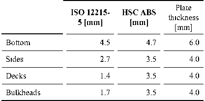
It was decided to select a bottom plate thickness 27% higher than obtained by HSC-ABS rules because both rules do not take into consideration possible hull- river bottom contacts and higher abrasives wear rates due to the riverine combat boats operative tasks.
From slamming design pressures and plates thickness (t) previously calculated, it can be estimated the required moment of inertia and section modulus for stiffeners. These both crosssectional properties were calculated considering the associated effective plating as 60*t [see table 5].
Table 5. Section modulus of stiffeners.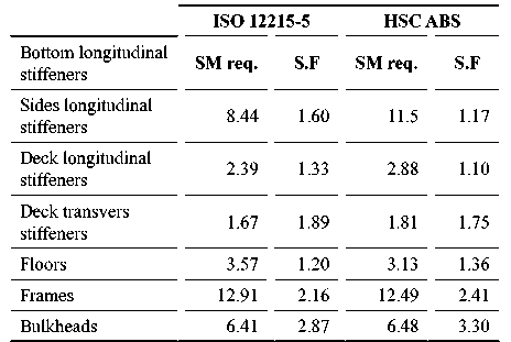
According to the presented results in table 5, it can be shown that all the selected profiles meet the section modulus rules requirements [22]. By relating the minimum section modulus requirements of both rules; profiles section modulus requested for HSC by ABS are slightly more conservatives in most cases.
Despite the fact slamming bottom pressures differences between both classification societies’ rules are close to 8,9%, the section modulus requirements differ in 36%; design bottom pressures represent a higher influence factor in HSC rules.
In this section, the direct analysis results are explained. First, the 6 mm thickness bottom hull presented low stress levels by slamming pressures close to the chine, then, it was decided to reduce the bottom thickness to 4 mm in this zone given that chine is also reinforced with round-bars and a bulb profile [see Fig. 8].
Fig. 8. Slamming stress distribution in the bottom.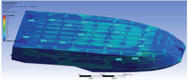
The highest stress level (close to 55.8 MPa) can be found in the bow between frames 9 and 10 [see Fig. 8]. These stress levels might be due to the hull’s geometry, this zone, given its geometry, is not reinforced with bulb profiles. Nevertheless, a 2.2 safety factor is expected. When the obtained safety factor is compared to the 1.27 bottom thickness ABS scantling safety factor it is discernible how conservative the scantling approach might be.
During the first steps of design process, it was intended to remove the round-bars from sidechine and bottom- chine welded connection for weight reduction [see Fig.2]. However, the utility of these bars is to improve the available welding surface area and raising stiffness. Because the use of these round-bars is not explicit considered in scantling rules, their effect was evaluated by the finite analysis method. Regarding this issue, beam type elements with cross section properties equivalent to the round-bars were added, it was found that chine stress levels showed a 30% stress level reduction [see Fig. 9].
Fig. 9. Round-bars effects in chine stress distribution.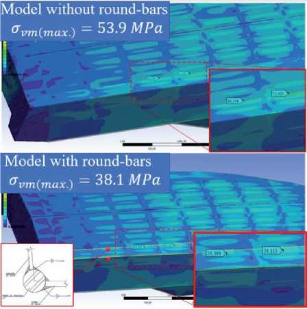
On the other hand, both longitudinal and transverse vessel reinforce panels showed safety factors of 67% and 41% higher respectively in comparison with scantling calculations and, hence, a more conservative approach from Classification Societies rules. In the next table, safety factor results of direct analysis and scantling are detailed [see table 6]. There is nonheat affected zones that despite presenting high stress levels, these present elevated yield strength properties, such as the case of hull’s sides and deck [see Fig. 10].
Table 6. Safety factors and stress levels of stiffeners.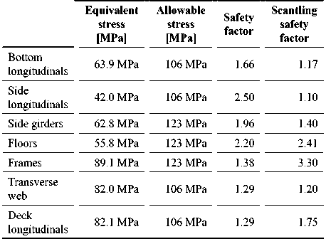
From table 6 results, in most cases, safety factors reported by direct analysis are higher than the calculated by classification societies scantling rules. However, spotted stress concentration safety factors in deck longitudinals, floors, and frames are shown to be higher by the scantling approach [see Table 6].
This could be explained given the limitations of the scantling rules related to geometry and stress concentrations in some connections as these rules only consider spacing, the length between supports, hull pressures and design stress. Even so, stress levels in these elements are below the design stress and the effect of stress concentration zones are deemed local [see Fig. 11].
Fig. 11. Stress levels in a typical frame.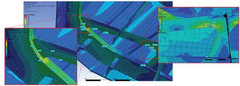
Static structural analysis was performed on critical structural details and focalized regions with equivalent stresses over the allowable value. Localized areas of high stress arising from geometry are not a concern since localized plastic deformation will not compromise overall strength. Also, localized plastic deformation would imply strain hardening and a slight loss of ductility. The spotted high stresses, which maximum value is close to 140 MPa, are remarkably below than aluminum tensile ultimate strength at heat-affected zones [see Fig. 12].
Fig. 12. Equivalent stress over 100 and 120 MPa.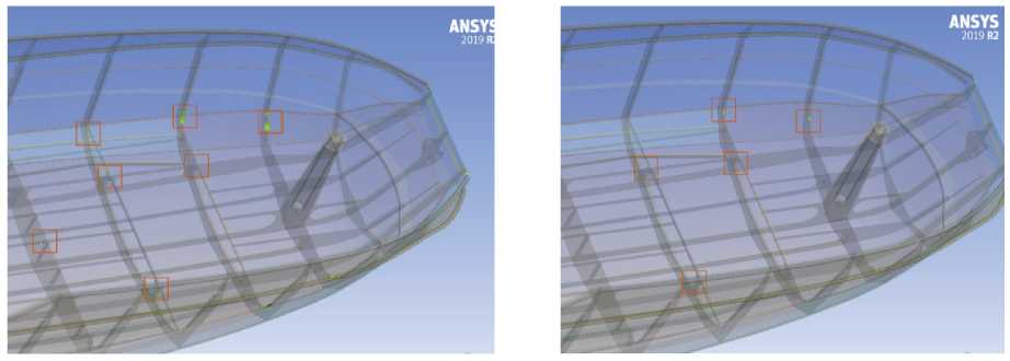
Structural details are characterized by high stiffness at their end connections and sharp corners. That ends might produce singularities; which means, there are points in the model where stress values tend towards non-real infinite values. If mesh convergence cannot be reached in certain high-stress points even with mesh refinement, these points are deemed to be singularities.
A high gradient stress zone was spotted at the port gunwale, after mesh convergence was not reached; the reported high stress values are deemed as a singularity [23] [see Fig. 13].
Fig. 13. Gunwale singularity.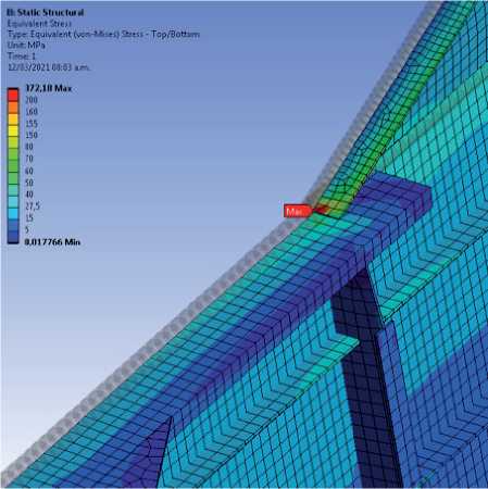
The following assessed structural details, after their mesh convergence was found, showed relatively high stresses in their end connections. First, transverse webs - side girders bracket connections stress levels were analyzed. In general, the stress is moderate and typically below 70 MPa but the upper bracket toe presents localized 125 MPa stress values due to stress concentration [see Fig. 14-left]. Given a design yield strength of 123 MPa at welded conditions, these stress values would not compromise the overall bracket strength, considering fillet welds might reduce the effects of the bracket toe’s sharp edge.
Fig. 14. Transverse web- side girder connection (left) frame-to-deck connection (right).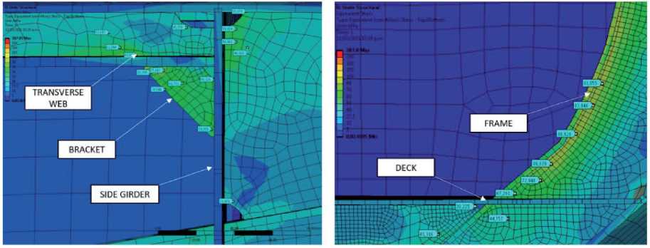
Regarding the frame-deck intersection, typically below 90 MPa stresses were reported in frames due to their curvature near the deck [see Fig.14- right].
The connection between deck longitudinals and bulkhead stiffeners was also revised [see Fig. 15-left]. Near bulkheads, deck longitudinals present stress levels close to 86 MPa, specifically in connections with bulkhead stiffeners. These stress levels are not a concern given they are below the allowable design stress.
Fig. 15. Deck longitudinals and bulkhead connection (left) side girder and bulkhead connection (right).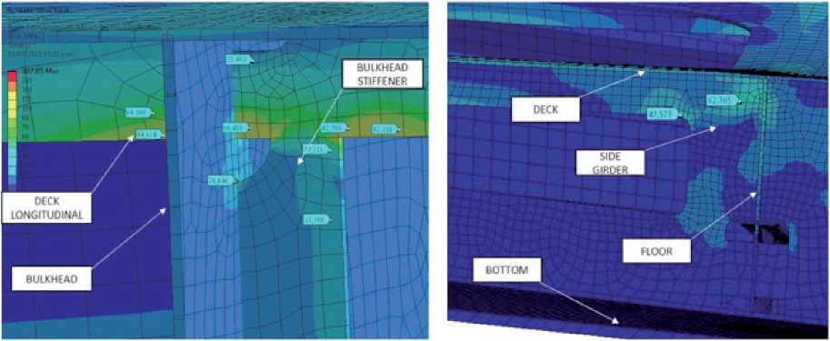
A maximum 63 MPa stress value was found near the deck and the side girder - bulkhead connection between frame 7 and 8 [see Fig. 15 - right]. The high stress influence is limited among the upper radius of the girder’s lightening hole, the bulkhead and deck.
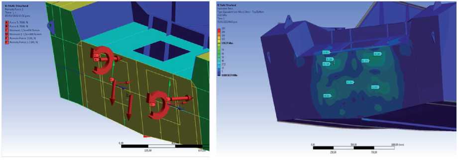
The Transom structural arrangement was designed to withstand two outboard motors’ continuous operation of up to 7000 N thrusts each and an individual 210 kg weight. In the early stages of this design process, the transom was thought of as a 12 mm thickness Al-5083 plate. Nonetheless, by direct analysis, it was possible to support the thickness reduction of the transom plate.
The structural arrangement of the transom is composed of a 10 mm thickness plate between side girders and 6 mm outside of them. Internally, the outboard motors are supported by the side girders and the rest of the transom is stiffened with flat-bar profiles and a single transverse bulb profile.
The applied loads and the obtained stress distribution on the 10 mm plate are shown next.
A 45 MPa maximum stress value was reported on transom plate and, therefore, a safety factor of 4.4. It was decided to allow this safety margin taken into consideration aft collision loads, vertical shear forces; as result of outboard motors impacts with objects in the riverbed and future motor updates.
Transom plate reinforcements present equivalent stress values below 50 MPa except for reinforcements at 250 mm from the centerline. These Al- 6082 -T6 profiles present local stress levels close to 140 MPa. This magnitude is only reported in non-heat affected zones, so the allowable design stress takes a value relative to 190 MPa and a 1.35 safety factor [see Fig. 17].
Fig. 17. Equivalent stress on transom structure.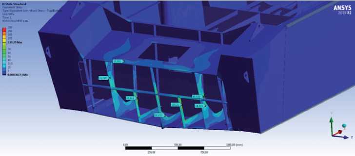
A modal analysis was performed principally to estimate the effects of operating outboard motors frequencies on the structural arrangement natural frequencies. 10 vibration modes were evaluated; 5 of which imply transom vibrations while the rest of vibration modes refer to negligible amplitudes in the structural arrangement and can be neglected [see Fig. 18].
Fig. 18. Vibration modes of the structural arrangement.
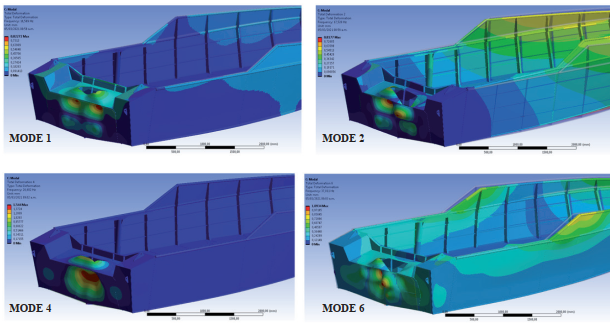
According to datasheets provided by the manufacturer, the highest operative motor frequency is 155 Hz and the idle frequency of 22 Hz. The idle frequency is 25% higher than the second vibration mode with a consequent amplitude of 0.81 mm. In the same way, idle frequency is 15% lower than the fourth vibration mode with and associated amplitude of 1.5 mm. In both cases, resonance amplitude is below the maximum allowable deflection which depends on the spacing between stiffeners and plate thickness [24].
Eigenvalue buckling test was performed to ensure an adequate behavior of the structure under compressive loads. The analyzed modes found a load multiplier factor equal to 4.66; given a load multiplier factor higher than 1.0 this structure will not present failure by buckling [see Fig. 20].
Fig. 20. Buckling load multiplier factor affected zone.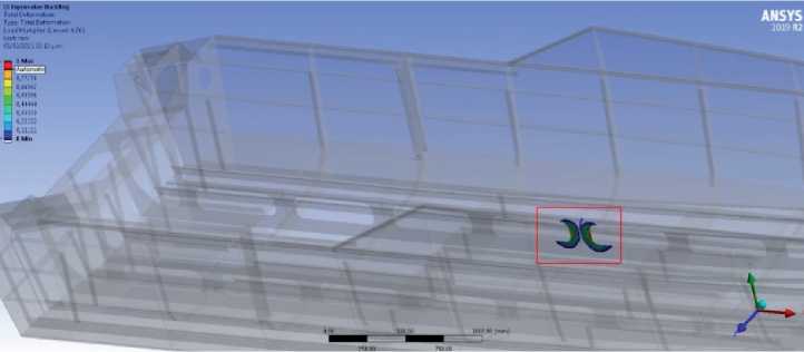
The designed structural arrangement for a riverine low-draft combat boat meets all requirements stipulated in both HSC- ABS and ISO 12215 scantling rules.
In most of cases, scantling requirements are more conservatives in HSC-ABS rules [3] than stipulated in ISO 12215 [4].
The performed direct analysis reported safety factors, in most cases, higher than obtained by scantling rules and, therefore, the direct analysis approach is prone to be less conservative. Nevertheless, there are cases where direct analysis presents lower safety factors. This might be because of scantling rules limitations related to structure geometries and stress concentrations. The structural arrangement natural frequencies are out of range from operative outboard motors frequencies. The idle frequency is 15% lower than one of the transom vibration modes, but, due to deformation amplitude is below the maximum allowed, safety operations of the vessel are not deemed affected.
From linear buckling analysis it can be shown that no structural elements will be failing by compressive loading instabilities.
The authors are very grateful for the constant support of The Science and Technology Corporation for Naval, Maritime and Riverine Industry Development (COTECMAR) and the Colombian Navy.
[1] F. ALVAREZ Y M. L. MEDINA, Guerra Fluvial Irregular: Fuerzas de Combate en los Rios de América, Madrid: IDS. Navantia, 2012.
[2] COTECMAR, «BCFBC. Manual de Usario,» Cartagena de Indias, 2020.
[3] A. B. o. S. ABS, Rules for building and classing. High-Speed craft. Part 3: Hull Construction and Equipment, Houston, TX. USA: ABS, 2020.
[4] International Organization for Standarization, Small Craft - Hull construction and Scantlings - Part 5: Design pressures for monohulls, design stresses, scantlings determinaion, ISO, 2014.
[5] Det Norske Veritas Germanischer Lloyd's DNV-GL, DNV-GL-CG-027- Class Guideline- Finite Element Analysis, 2015.
[6] B. YONG Y J. WEI-LIANG , «Chapter 8 -Scantling of Ship's Hulls by Rule,» de Marine Structural Design, Butterworth-Heinemann, 2016, pp. 153-170.
[7] K. ANYFANTIS, «Ultimate strength of stiffened panels subjected to non-uniform thrust,» International Journal of Naval Architecture and Ocean Engineering, vol. 12, pp. 325-342, 2020.
[8] D. VAN TUYEN , B. LIU, Y. GARBATOV, W. WU Y C. GUEDES SOARES, «Strength assessment of aluminium and steel stiffened panels with openings on longitudinal girders,» Ocean Engineering, vol. 200, 2020.
[9] J. K. PAIK, «Characteristics of welding induced initial deflections in welded aluminum plates,» Thin-walled Structures, vol. 45, pp. 493-501, 2007.
[10] Ship Structure Committe, SSC-218 Design Considerations for Alluminum Hull Structures, Washington D.C: Ship Structure Committe, 1971.
[11] R. SIELSKI, «Research needs in aluminum structure,» Ships and Offshore Structures, vol. 3, pp. 57-65, 2008.
[12] N. NAZEMI, F. GHRIB Y J. SOKOLOWSKI, «The HAZ in Aluminum Welding Revisited,» 3rd Specialty Conference on Engineering Mechanics and Materials, 2013.
[13] J. PAIK, J. LEE, M. RYU, Y. JANG, H. RENAUD Y P. HESS, «Mechanical buckling collapse testing on Aluminium stiffened plate structures for marine applications,» The World Maritime Technology Conference, 2006.
[14] M. COLLETTE, «Strength and Reliability of Aluminium Stiffened Panels,» Ph.D submission School of Marine Science and Technology, Faculty of Science, Agriculture and Engineering, University of Newcastle, 2005.
[15] B. CHEN Y C. GUEDES SOAREs, «A Simplified Model for the Effect of Weld-Induced Residual Stresses on the Axial Ultimate Strength of Stiffened Plates,» Journal of Marine Science and Application, vol. 17, pp. 57-67, 2018.
[16] P. HERRINGTON Y R. LATORRE, «Development of an aluminum hull panel for high-speed craft,» Marine Structures, vol. 11, pp. 41-71, 1998.
[17] B. LIU, R. VILLAVICENCIO Y G. S. SOARES, «On the failure criterion of aluminum and steel plates subjected to low-velocity impact by a spherical indenter,» International Journal of Mechanical Sciences, vol. 80, pp. 1-15, 2014.
[18] B. LIU, S. WANG, R. VILLAVICENCIO Y C. GUEDES SOARES, «Slamming load and hydroelastic structural reponse og bow flare areas of aluminium fast displacement crafts,» Ocean Engineering, 2020.
[19] B. YONG Y J. WEI- LIANG, «Chapter 8: Ship Hull Scantling Design by Analysis,» de Marine structural design, 2016, pp. 171-180.
[20] American Bureau of Shipping, Guidance notes on Structural Direct Analysis for HighSpeed Craft, Houston: ABS, 2018.
[21] Lloyd's Register, Rules for the manufacture, testing and certifications of materials, London: Lloyd's Register Group, July 2020.
[22] COTECMAR, «Cálculos de Escantillonado del Bote de Combate Fluvial de Bajo Calado - BCFBC,» Cartagena de Indias, 2020.
[23] E. NIEME, W. FRIKLE Y S. MADDOX, «Structural Hot- spot Stress Determination Using Finite Element Analysis,» de Structural Hot-Spot Stress Approach to Fatigue Analysis of Welded Components, IIW Collection, 2018.
[24] Lloyd's Register, Rules and regulations for the classification of special service craft, London, July 2020.