Ship Science & Technology - Vol. 15 - n.° 29 - (9-19) July 2021 - Cartagena (Colombia)
DOI: https://doi.org/10.25043/19098642.217
David Sagástegui 1
D.Sc. Nain Ramos 2
1 Universidad Nacional de Ingeniería. Mechanical Engineer Department. Lima, Perú. Email: dsagasteguic@gmail.com
2 Universidad Nacional de Ingeniería. Mechanical Engineer Department. Lima, Perú. Email: nramosa@uni.edu.pe
Date Received: April 15th, 2021 - Fecha de recepción: 15 de abril del 2021
Date Accepted: July 21st, 2021 - Fecha de aceptación: 21 de julio del 2021
The naval industry has integrated the generation of energy through nuclear processes, due to the large amount of energy that is produced in these processes, for example, the ship NS OTTO HAHN, which used a propulsion plant with energy generated by a reactor of pressurized water (PWR), which operated under a nuclear fission process. Also, other examples are military ships and icebreakers. In order to know the energy contribution of this type of nuclear propulsion plants, this work carries out a multiphysics analysis of a PWR reactor, considering a turbulent behavior for the fluid that comes into contact with the uranium rods. Finally, the results of the fluid velocity fields along the fuel elements and the outlet nozzles are presented, as well as the temperature fields inside the reactor.
Key words: NS OTTO HAHN, nuclear fission, nuclear propulsion, multiphysics, PWR reactor.
La industria naval ha integrado la generación de energía mediante procesos nucleares, debido a la gran cantidad de energía que se produce en dichos procesos, por ejemplo, el buque NS OTTO HAHN, el cual utilizó una planta de propulsión con energía generada por un reactor de agua presurizada (PWR), que operó bajo un proceso de fisión nuclear. Además, otros ejemplos son los buques militares y los buques rompehielos. Con la finalidad de conocer el aporte energético de este tipo de plantas de propulsión nuclear, este trabajo realiza un análisis multifísico de un reactor PWR, considerando un comportamiento turbulento para el fluido que tiene contacto con las varillas de uranio. Finalmente, son presentados los resultados de los campos de velocidad del fluido a lo largo de los elementos de combustible y de las toberas de salida, así como los campos de temperatura en el interior del reactor.
Palabras claves: fisión nuclear, multifísico, NS OTTO HAHN, propulsión nuclear, reactor PWR.
Nuclear propulsion systems have been investigated due to the large amount of energy they generate, despite this, there are certain factors by which the energy generated cannot be used efficiently. Among them, the most widely used is the PWR reactor (Pressurized Water Reactor). These types of reactors are very stable due to their tendency to reduce their power in the face of increases in temperature, this helps to reduce the possibility of losing control of the chain reaction [1].
Its operation is based on fission reactions, which occur in the fuel rods, located inside, which behave as a heat sink. In addition, they use water as a coolant that is highly pressurized to keep the water in the liquid phase [1] at the operating temperatures of the reactor. This places demanding requirements on the pipes and the pressure vessel of the reactor and therefore increases construction costs and the risk of an accident with loss of coolant from the primary system [2]. That is why PWR reactors are the subject of research, which have been studied from the fuel rods to the structure of the reactor in general.
In the present work, a local and global study has been carried out. The local study consists of the simulation of the fuel rods that have been studied and computationally modeled in detail, applying knowledge of heat transfer, in the work called "Modeling of heat transfer in the fuel rods of the PWR nuclear reactor”. The results obtained in this work have been qualitatively validated with generally accepted operating curves [3]. The results obtained in the local study are validated with those obtained in the previously mentioned work. In addition, the results of the local study are the basis for developing the global study on fuel elements and the PWR, to carry out an energy analysis.
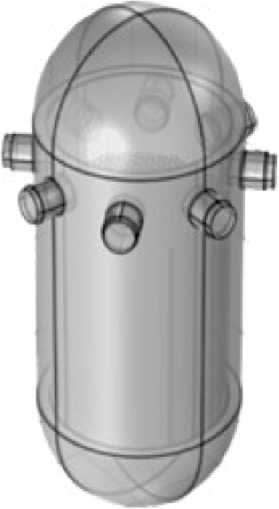
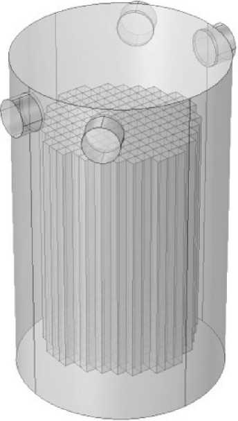
The present research work takes the PWR reactor as its object of study (Fig.1) to which local and global studies have been carried out.
Figura 1. Isometric view of the PWR reactor.
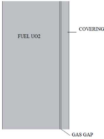
Table 1 shows the geometric characteristics of the fuel rod, which is made up of a metal tube, which acts as a coating to retain the radiation produced inside by the cylindrical Uranium dioxide pellets. Between the outer surface of the pellets and the coating, there is the gas gap [3].
Table 1. Geometric characteristics of the fuel rod [1].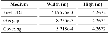
Table 2 shows the geometric characteristics of the models used for the global study, made up of the thermodynamic study of the fuel element and the multiphysical study of the reactor, as shown in Fig.3 and Fig.4, respectively.
Table 2. Geometric characteristics of the global study [4].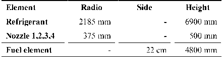

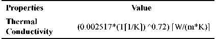
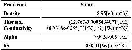
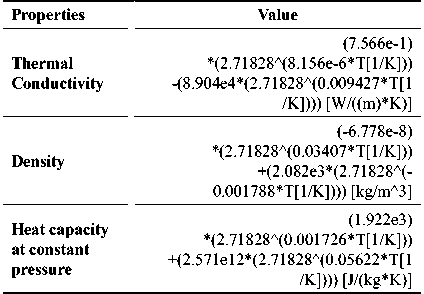
The fuel rod model is composed of 3 materials, which are characterized by equations dependent on temperature (T) and vertical position z, as shown in Table 3, Table 4 and Table 5. The fuel element is made up of UO2; the gap, covered with gas and the coating of Zircaloy-4.
Table 3. Characteristics of UO2 [3].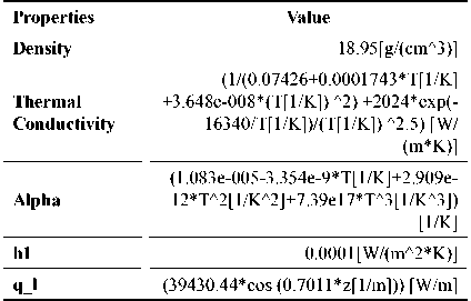
Inside the reactor, there is a light coolant, which serves as a support to maintain the temperature of the reactor, and generates water vapor, which is used to produce energy.
The local study was carried out with a multiphysical study of the fuel rod that was developed in an axisymmetric model, where the fuel acts as a source of heat, which will propagate in the form of radiation towards the coating of the rod.
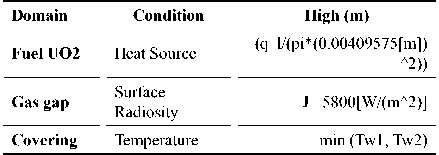
In the contour of the coating that is in contact with the refrigerant, the characteristics have been designated, shown in Table 7.
Table 7. Coating contour features [3].
To carry out the study, thermodynamic concepts have been used (Equation 1) that describe the heat transfer in the solid and fluid parts, which are found inside the fuel rod [5].
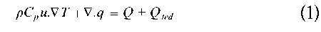
Where:
ρ: Density[kg/m3]
Cp: Specific heat capacity at constant pressure [J/kg. K]
u: Fluid velocity vector [m/s]
∇T: Temperature gradient[K/m]
Q: Heat Source[W/m3]
Qted: Thermoelastic damping [W/m3]
In the part of the gap of the rod, the heat is transferred in the form of radiation through the gas from the surface of the fuel to the surface of the coating, considered as opaque bodies, and the gas, as a transparent body. These designations are important to determine the radiosity on the surfaces.
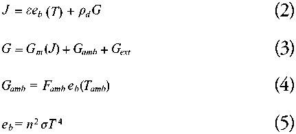
Where:
J: Surface radiosity [W/m2]
G: Surface irradiation [W/m2]
Cmb: Ambient irradiation [W/m2]
Gext: External irradiation [W/m2]
ε: emissivity
eb: Total hemispheric emissive power [W/m2]
T: Temperature[K]
Tamb: Ambient Temperature [K]
Famb: Ambient view factor
σ: Stefan-Boltzmann constant [W/m2K4]
p d: Density, damaged tissue[kg/m3]
n: transparent media refractive index
The radial profile of the temperature of the fuel rod in a PWR reactor that you must obtain in the computational results, must follow the same trend as shown in Fig.5, since these are the curves of the typical radial temperature profile [3].
Fig. 5. Typical radial temperature profile in PWR for two linear rates of heat generation [3].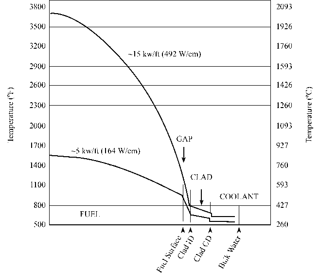
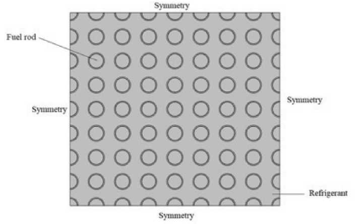
The global study was divided into 2. In the first stage, a time-dependent global analysis of the fuel elements was carried out, which are made up of a 17x17 arrangement of fuel rods. The same boundary conditions as in the local study were placed on this arrangement of rods, with the difference that in this study symmetry conditions were applied on all faces and it was considered that the refrigerant with a temperature of 553 K that moves between they, in the form of turbulent flow k-ε [4].
Turbulent flow is governed by the following equations [6]:
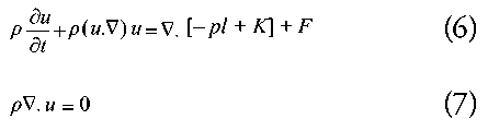
Where:

The transport equation for ε reads:
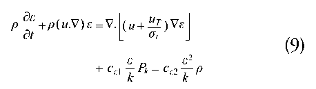
Where:
ε = ep: Turbulent dissipation rate
μ: Dynamic viscosity [Pa.s]
μτ: Turbulent dynamic viscosity
Pk: Production term
k: Turbulent kinetic energy [J/kg]
u: Velocity field [m/s]
ρ: Density[kg/m3]
p: Pression [Pa]
F: Volume Force [N/m3]
c ε2, c ε1 , σ ε: Model constants
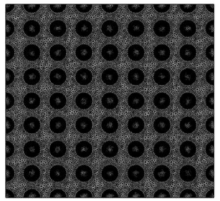
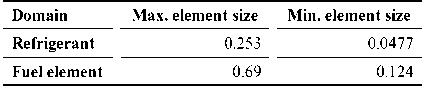
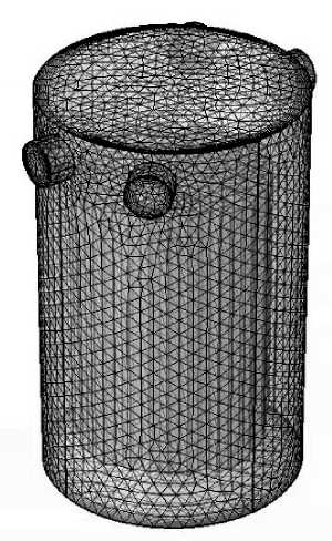
Additionally, a meshing was carried out considering the characteristics of the domains. In Table 9, you can see the minimum and maximum sizes of the elements and in Fig.7, you can see the meshing of the fuel element.
Table 9. Size of Elements of mesh of the fuel element.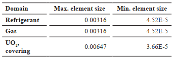
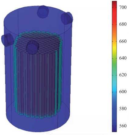
The second stage of the global study consists of a more comprehensive development of the reactor, made up of 157 fuel elements, an inlet and 4 coolant outlets with a k-ε turbulent flow characteristic.
Each fuel element is a source of heat, at an average temperature of all the rods found inside, obtained from the first part of the global study.
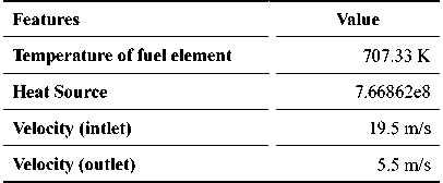
Fig. 8. Features of second global model.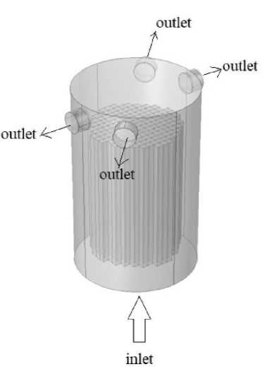
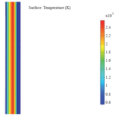
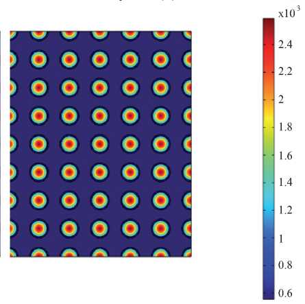
The temperature obtained as a result has a maximum value in the center of the fuel of approximately 2588 K and follows the trend of the typical temperature graph in the radial direction (Fig. 5), as can be seen in Fig.11, obtaining a high value in the fuel, which is decreasing in the direction of the coating. These values depend on the heat source and the radiation that is effected through the gas gap.
Fig. 11. Radial temperature prof le on the fuel rod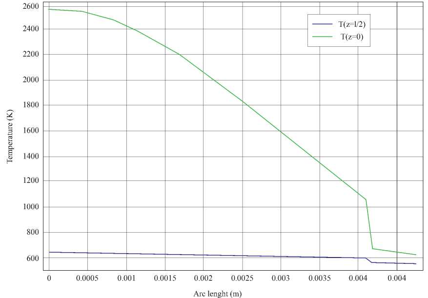
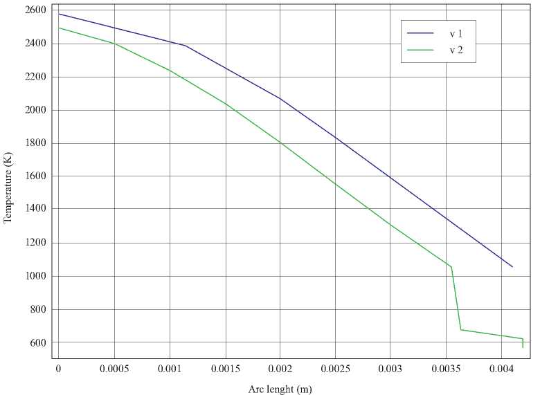
The results obtained in the first global study, the highest temperature is in the center of the fuel elements; however, these temperatures vary according to the location of the rod and time, for example, in Fig.14, the radial temperature profile is shown in 2 rods that are in different locations in a time of 60 seconds. In addition, an average temperature value of the system of 707.33 K was obtained, which is used for the second global evaluation, and the internal energy of the system shown in Fig.13, shows that heat is being transmitted from the heating rods. fuel to the coolant.
Fig. 13. Internal energy in the fuel element (t=60 s).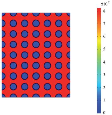
For the second global study, the results in an initial time show that the temperatures are below the temperature in a fission reactor for industrial heat that is 1000°C [7]; however, as time passes, extremely high temperatures of the degree of 10e4 are obtained, this is because in the simulation there is no fluid circulation, so the refrigerant is absorbing heat and will continue to increase its temperature. The internal energy of the system is in the order of MJ / s, as shown in Fig.16, which integrates the kinetic energy and the potential energy of the refrigerant, since gravity has been considered in the study. The velocity profiles in the nozzles show that the coolant outlet velocity does not present a homogeneous behavior, as can be seen in Fig.19, which may be part of the beginning of the problems of low efficiency in PWR reactors.
Fig. 16. Internal energy in the second global study.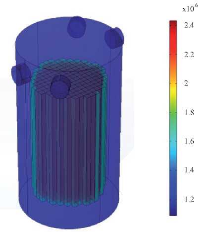
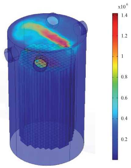
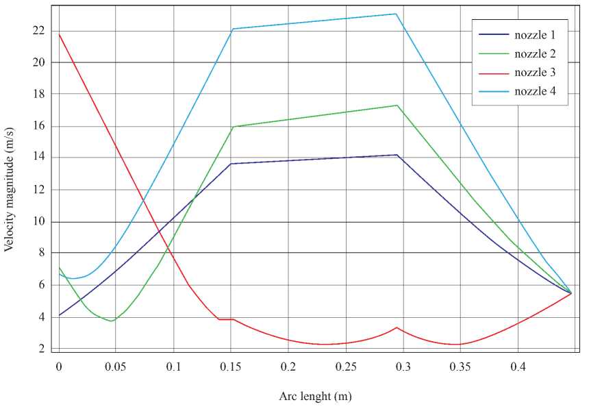
In the velocity profiles found in the nozzles, a variation is observed in the values reached, this can be caused by the production of a counter flow at the outlet of these, that is, by the turbulent nature of the fluid or by the impact of the flow on the walls of the nozzles, change their direction, opposing the exit velocity, which would imply, that a loss of kinetic energy occurs, and as a consequence it would reduce the efficiency of the reactor, since of the nozzles flow is directed to steam generators. It is here where the loss of energy begins, which will subsequently increase, as it travels, until it reaches the propellers in the form of electrical energy.
To thank the National University of Engineering, for providing excellent teaching to its students, to apply their knowledge in the development and innovation of naval technology. In addition, to the DSc. Nain Ramos Alvaréz, for the motivation and high-quality contribution, to achieve the advancement of both the naval engineering career, and the National University of Engineering.
[1] Colaboradores de Wikipedia. Reactor de agua a presión [on-line]. Wikipedia, La enciclopedia libre. 2021 [consultation date: February 2, 2021]. Available in: https://es.wikipedia.org/wiki/Reactor_de_agua_a_presi%C3%B3n.
[2] S, Díaz, Energía nuclear para la propulsión naval. Universidad de Cantabria. Cantabria, Escuela Superior de Náutica: Universidad de Cantabria, 2018.
[3] E, Muñoz, Modelación de la transferencia de calor en las varillas de combustible del reactor nuclear PWR. Santiago, Departamento de Ingeniería Mecánica: Universidad de Chile, 2011.
[4] T. Hohne et al., “Experimental and numerical mixing studies inside a reactor pressure vessel,” in 4th ASME/JSME Joint Fluids Engineering Conference., Hawaii, USA, 2003.
[5] The Heat transfer Module User's Guide, COMSOL 5.4. COMSOL Multiphysics., USA, 2018, pp .161-163.
[6] The CFD Module User's Guide, COMSOL 5.4. COMSOL Multiphysics., USA, 2018, pp .178-186.
[7] H. Barnert et al., “Energía nuclear para producir calor,” Organismo Internacional de Energía Atómica., Viena, Austria, Boletín del OIEA, 1/1991, 1991.