Ship Science & Technology - Vol. 14 - n.° 28 - (31-41) January 2021 - Cartagena (Colombia)
DOI: https://doi.org/10.25043/19098642.213
Daniel E. Riveros Nieto 1
1 Departamento de ingeniería mecánica, Universidad Nacional de Colombia. Medellín, Colombia. Email: deriverosn@gmail.com
Date Received: March 14th 2019 - Fecha de recepción: Marzo 14 de 2019
Date Accepted: June 3rd 2020 - Fecha de aceptación: Junio 3 de 2020
The process of optimized design, evaluation and manufacturing of high energy efficiency propellers for competition boats at scale is addressed in this research. This project uses the stages of hydrodynamic design, numerical testing and manufacturing of four prototypes as example. During the hydrodynamic design, three design methodologies were compared, namely: Blade Element Theory, lifting line theory and design based on DTMB propeller series. The objective function of the optimized design is based on obtaining the chord and pitch distribution that generates the greatest thrust, speed and efficiency. Similarly, the performance of each prototype was evaluated by CFD in a virtual channel registering thrust, torque and speed. Finally, the additive manufacturing process applied is presented. Prototyped propellers present efficiencies and maximum speeds approximately 15% higher than recommended commercial propellers for this type of boats. This study was developed by the Hydrometra group in the framework of the international competition Hydrocontest 2017.
Key words: Propeller, naval propulsion, energy efficiency, hydrodynamic design.
En esta investigación se aborda el proceso de diseño óptimo, evaluación y fabricación de hélices de alta eficiencia energética para barcos de competición a escala. Este proyecto utiliza como ejemplo las etapas de diseño hidrodinámico, ensayos numéricos y la manufactura de cuatro prototipos. Durante el diseño hidrodinámico, se comparan tres metodologías de diseño, a saber: Teoría de los elementos de palas, teoría de línea de sustentación y diseño basado en la serie de hélices DTMB. La función objetivo del diseño optimizado se basa en la obtención de la distribución radial de cuerda y paso que genere el mayor empuje, velocidad y eficiencia. Del mismo modo, se evalúa el rendimiento de cada prototipo mediante CFD en un canal virtual registrando empuje, momento y velocidad. Finalmente, se presenta el proceso de fabricación aditiva aplicado. Las hélices prototipadas presentan eficiencias y velocidades máximas aproximadamente un 15% superiores a las hélices comerciales recomendadas para este tipo de embarcaciones. Este estudio fue desarrollado por el grupo Hydrometra en el marco del concurso internacional Hydrocontest 2017.
Palabras claves: Hélice, propulsión naval, eficiencia energética, diseño hidrodinámico.
Naval propulsion based on propellers has been an efficient and reliable propulsion method (Carlton, 2010). The design of these propellers has evolved gradually in tandem with the development of theories whose objective is to model the hydrodynamic phenomena associated with the generation of lift and drag forces in a rotating solid on which a flow impinges. Throughout the study of hydrodynamics, these theories have increased their accuracy and complexity. Initially, the modification of the momentum in an incident flow to a rotating porous disk was considered, which extracts from or delivers to the momentum flow (Mejía, 2005). Later, the geometry of the rotor blades on which the flow impinges was considered, this is done by the two-dimensional evaluation of the forces exerted by the flow on an aerodynamic profile in relation to its chord and angle of incidence, afterwards, this information is computes in different radial sections of cross or elements of cross that, finally, reproduce the action of the cross as the summation of the actions of each element of cross (Mejía, 2005) (Marten, 2013).
Then, the lift - line theory or lift line is developed, which identifies the circulation of the vortices around the solid as the generator of the lift phenomenon and by means of the integration on radial sections it allows to know the force that is exerted on the whole of the propeller, this theory is widely treated in (Flood, 2008), (Chung, 2007), (Epps, 2016) and (Epps, 2013). This theory has been transferred to computer codes that facilitate the computation of the properties of propellers to achieve optimal designs. Among these codes are commercial versions and some versions of free use as OpenProp (Epps, 2013), software used in this study.
Another classic approach in the design of propellers refers to series of propellers registered in the literature that can be considered as an initial basis for the design of a propeller. These series have dimensionless geometries based on the length of the chord; this allows adapting the design to geometric design requirements, conserving the properties of the propellers originally developed during the generation of the series of propellers (Carlton, 2010). Some of these series are DTMB (Brizzolara, 2008) and Wageningen B series (Oosterveld, 1975).
In addition, methods for evaluating the performance of propeller prototypes have recently emerged through Computational Fluid Dynamics (CFD), this approach allows, in general, to know in broad strokes the performance of the propellers and the alteration of the surrounding flow (Brizzolara, 2008), (Trejo et al., 2017) and (Kulczyk., 2007). It is thus possible to estimate the forces on the propellers and the distribution of pressure on its surface, a phenomenon related to the presence of cavitation on the surface of the propeller. It should be noted that there are different studies that make comparisons between different approaches to design a propeller, as seen in (Knutsen, 2016) and (Gur, 2008).
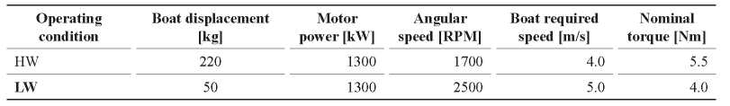
In the present work the geometrical design of propellers is proposed to generate two final propellers assigned to the two required operating conditions described as Heavyweight (HW) and Lightweight (LW) conditions. Therefore, the two required operating conditions, based on the different races of the contest, are described in the (Table 1).
Table 1. Required operating conditions for the contest.
The design of proposed propellers for these conditions is made by means of several design methods, such as design based on the DMTB series adapted to the operating conditions of the propellers to be designed, an optimized design by means of the blade element and momentum theory and another optimized design through the theory of lifting-line in the OpenProp software. This design approximations are shown below with the modifications made for the present design case.
DTMB Series: The DTMB series, developed in the David Taylor Model Basin, consists of a family of immersion propellers complete and absent of cavitation that have three or more blades, whose pitch varies along its radial axis. The geometry of these propellers is represented in a dimensionless way through standard tables whose base is the modified NACA 66 profile and curvature line a = 0.8 (Brizzolara, 2008). The DTMB series includes three-bladed propellers (DTMB 4119), four-bladed (DTMB 4381), and five-bladed propellers (DTMB 4382, 4383 and 4384). Examples of this series are presented in (Fig. 1).
Fig. 1. Examples of DTMB propeller series. (Brizzolara, 2008).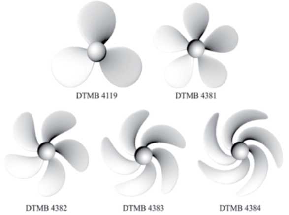
As mentioned above, the design of the propeller has as a technical requirement: the generation of a three-blade propeller, therefore, the DTMB propeller is selected as the basis for the geometry of the propeller to be designed. (Table 2) shows the dimensionless standard table of the DTMB 4119.
Table 2. Standard dimensionless parameters of the DTMB 4119 propeller. (Brizzolara, 2008).
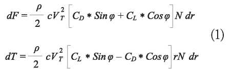
Blade element and momentum theory (BEMT): This theory joins the relationship between the angle of incidence and the length of the chord with the force on the paddles and the torque on them.
This considers force differentials and moment differentials that are exerted on a radius differential in a blade, which is extrapolated between blade sections. These differentials are related to the drag and lift coefficients for each aerodynamic profile that shapes the blade element; In addition, these coefficients are related to the angle of incidence of the blade element that is defined by the relative speed of the blade determined by the speed of rotation and the speed of entry of the air flow, as shown in (Fig. 2).

Lifting-line theory: This theory considers each vane as a line of support with vorticity at the exit aligned with the local velocity of the flow. In addition, each palette divides the palette into discrete radial sections, having properties of the two-dimensional aerodynamic profiles in each section (Epps, 2013).
From there, the charges are computed by integration over the entire length of the blade of the charges in each two-dimensional radial section. As shown in (Fig. 3). The application of this theory is done through OpenProp software (Epps, 2013) developed at the Massachusetts Institute of Technology in MATLAB.
Fig. 3. Diagram of forces in a radial section of a blade (Epps, 2013)..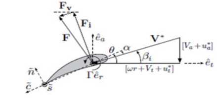
The input data required varies depending on the module used, but in general are: diameter, family of aerodynamic profiles, thrust or required thrust coefficient, speed of advance of the boat and angular velocity of the propeller at the design point, power on the axis, among others. The software covers a large part of the design stages, from a parametric study whose result is the optimum diameter for the propeller considering the motor and the required thrust. In addition, output variables for the optimized design modules are chord distribution, angle of incidence, aerodynamic profile, thrust coefficients, torque and efficiency. These data can then be processed in such a way that they are comparable to other prototypes or commercial propellers, as shown in the following sections.
Comparison by lifting-line theory: Through the OpenProp software, the comparison of the four propeller designs was made to determine which are the best designs and the features they offer in relation to the other designs. Since the four designs are dissimilar, the study was made based on four dimensionless numbers that allow a reliable comparison, according to the theory of dimensional analysis. These numbers are the coefficient of advance J, coefficient of thrust Kt, coefficient of torque Kq and hydrodynamic efficiency ηHydro, expressed respectively as follows:
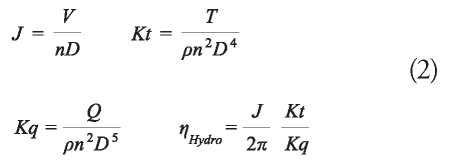
Where V is the forward speed of the boat or velocity of the incoming flow to the plane of rotation of the propeller, n is the angular velocity of the propeller in revolutions per second, D is the diameter of the propeller, p is the density of the fluid, T is the thrust force that is generated on the surface of the propeller and Q is the torque of the propeller.
Finally, the presence of cavitation on the suction side of the blades is evaluated for the selected propellers based on the cavitation inception criteria. The cavitation will occur when the minimum negative pressure coefficient, Cp, is equal to the cavitation number, σ (Molland, 2007). Therefore, the cavitation will be present in the zones of the blade where,

Obtained Geometries: Through the methodologies presented, four propellers are obtained. All geometries present a skew radial distribution based on the original distribution of the DTMB 4119 propeller because the effect of the skew on the performance of the propeller is out of the reach of this analysis.
For each design, the front view of the vanes and the distribution of the chord, curvature and thickness of the profile in different radial positions, respectively, are presented. In addition, for all designs, a nose or hub of 7 cm in diameter was taken as the reference, like those available in the market.
DTMB Series (DTMB): Based on the DTMB series, the geometry presented in (Fig. 6a) is obtained. From this, it can be highlighted that it provides the blades with the profiles with the largest chord for the radial sections of which it is composed.
Fig. 6. (6) (Left) Radial sections of the geometry obtained by the specified methods. (Right) Front view of the geometry obtained by the specified methods.a) DTMB; b) LLS; c) LLH; d) BEMT
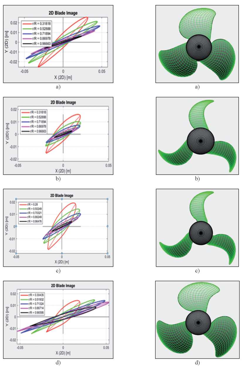
Lifting-Line Speed (LLS): By defining optimization parameters according to a velocity propeller, smaller diameter and maximum angular velocity, 0.22 m and 2500 RPM respectively, a first design was obtained by optimization, based on the liftline theory, called LLS propeller. This propeller, in relation to the other designs, is the one that has the smallest length of chord for each of its radial sections. This geometry is presented in (Fig. 6b).
Lifting-Line Heavyweight (LLH): For the second design by means of the OpenProp free software, ;optimization parameters were defined according to a thrust propeller or heavy load transport, larger diameter and lower maximum angular speed, 0.25 m and 1700 RPM respectively, a first design was obtained by optimization, based on the hydrodynamic theory of lifting-line, called heavyweight propeller.
Based on these two designs, it can be a ffirmed that the optimization reduces the chord in the cross sections and therefore the surface area of the propeller. This design is presented in (Fig. 6c).
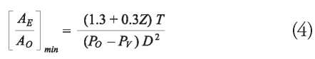
Blade Element Momentum Theory (BEMT): The fourth one designed represents the optimization methodology through BEMT. In this, a minimum total surface area was considered to reduce to the maximum the presence of any type of cavitation on the surface of the pallets. The mentioned minimum area was determined by means of the formula suggested by Keller [18], which relates the ratio of minimum expanded area to avoid cavitation with the diameter of the propeller D, the static pressure at the centre of rotation of the propeller Po, the steam pressure of the water for the conditions in which the propeller Pv operates, the number of paddles Z, the maximum expected thrust T and a correction coefficient whose value corresponds to 0 for a very high speed propulsion, 0.1 for boats propelled by two propellers and 0.2 for propulsion by a single propeller. This formula is expressed as:
The optimization was then applied to a propeller of 0.22 m in diameter and the geometry shown in (Fig. 6d) was obtained. This propeller has the longest cord length in its radial sections compared to the three designs presented above.
Finally, the four obtained propellers are summarized and characterized by their main geometrical properties in the (Table 3).
Table 3. Summary and characterization of the obtained propellers. P/D: pitch/diameter, EAR: Expanded Area Ratio.
In order to select the two best propellers for the speed and heavy load vessels that will participate in the contest, comparative graphs were made for each coefficient considering the four proposed designs, these graphs are presented for Kt, Kq and ηHydro in the (Fig. 7). As a result of this comparison, the design Speed is selected as a propeller for speed and the Heavyweight design for heavy load, because it presents the efficiency and thrust coefficient of greater value in the range of coefficients of advance of interest. These geometries are processed by CAD software to be the basis of CFD simulations and to be manufactured for experimental tests.
Fig. 7. Performance charts for the designed propellers. (Blue: Speed propeller, Red: Heavyweight propeller, Black: BEMT propeller and Green: DTMB propeller).
a) Thrust coefficient vs. advance coefficient.

b) Torque coefficient vs. advance coefficient.

b) Hydrodynamic coefficient vs. advance coefficient.
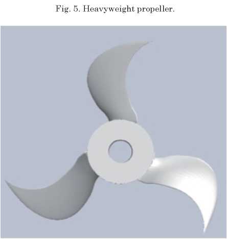
Mentioned CAD-processed geometries are presented as a heavy load propeller and speed propeller in (Fig. 4) and (Fig. 5), respectively.
Fig. 4. Speed propeller.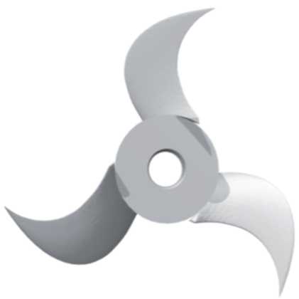
In addition, it is possible to observe that the Speed propeller is the one with the highest hydrodynamic efficiency in the entire range of advance coefficients, which is why it is the adequate propeller for the energy efficiency category that is part of the contest.
Propellers manufacturing: Based on the CAD geometries obtained, the propellers for the category of speed and the category of heavy load are manufactured by means of additive manufacturing in ABS M30. These propellers are shown in (Fig. 8) and (Fig. 9).
Fig. 8. Speed propeller prototyped by means of additive manufacturing in ABS M30.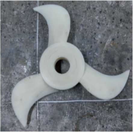

CFD lifting-line non-dimensionless results: The results obtained by means of the computational application of the lifting-line theory are integrated to the performance data of the motor (exclusive property of the manufacturer) and presented as the final charts of performance of the complete propulsion system for the two selected propellers (Fig. 10) and (Fig. 11).
Fig. 10. Thrust generated by the propulsion system as function of the advance speed for the two operating conditions.
Finally, the possible cavitation is evaluated for the LLH and LLS propellers, the distribution of the relation described in the (Equation 3) is plotted on the suction side of their blades in order to identify the points where the relation is equal to 1 for sea water under standard conditions. The (Fig. 12) shows the lack of cavitation inception in the suction side of their blades, the most critical side due to the low pressure required to generate the propulsion of the ship.
Fig. 12. Field of the cavitation relation -Cp/σ on the suction sides of the LLH and LLS propellers.
From the results obtained by means of the liftingline theory, it is possible to affirm that the propeller prototypes with the best performance are the propellers optimized by the lifting-line theory. This is because their hydrodynamic efficiencies are around 10% higher than the coefficients of the other two designed prototypes. In addition, it is concluded that the lifting-line theory and the optimization methods based on this, allow obtaining propellers with greater hydrodynamic efficiency, that is, it manages to more efficiently convert the input power into useful lift force avoiding high losses due to slippage and drag.
By means of the comparison of the results obtained by experimentation and by CFD simulation, it can be concluded that, due to the complexity of the geometry, since this is defined in a parametric way by guidelines, the mesh needs to be deformed excessively, which can imply that it does not capture the viscous phenomena that occur on the surface of the propeller and the pressure differences that act on it, responsible for the lift and drag forces. In addition, the results of cavitation by means of CFD are not conclusive since they underestimate the generated thrust, which is directly related to the pressure difference between the high and low-pressure faces of the propeller, criteria used to identify areas where cavitation may occur.
As future work several development points are recognized that can benefit the design of propellers, these points are: to realize a dynamic experimental assembly, to include the effects that provoke on the propeller the hull or the hulls of the boat, implementation of a mechanical system that allows the variation of the passage of the blades while they are in operation, and simplifying the method of obtaining the geometries to achieve meshes of higher quality.
The author thanks the Faculty of Mines of the National University of Colombia for the financial and logistical support provided for the realization of this study. In addition, thanks to the Hydrometra team for their diligent work that made it possible to achieve this new development with a view to the Hydrocontest 2017. Finally, thanks to COTECMAR for the support on the development of the naval engineering knowledge and industry in Antioquia.
[1] A. MOLLAND and S. TURNOCK, Marine rudders and control surfaces. Oxford: Elsevier/Butterworth-Heinemann, 2007.
[2] B.P. EPPS and R.W. KIMBALL, OpenProp v3: Open-source software for the design and analysis of marine propellers and horizontalaxis turbines. URL: http://engineering.dartmouth.edu/epps/openprop, 2013
[3] B.P. EPPS, "On the rotor lifting-line wake model", Journal of Ship Production and Design, vol. 32, 3:1-15, 2016.
[4] B.P. EPPS, R.W. KIMBALL, "Unified Rotor Lifting-line Theory", Journal of Ship Research, vol. 57, 4:1-21, 2013.
[5] C. JENG-HORNG, S. YU-SHAN, “Basic design of a series propeller with vibration consideration by genetic algorithm”, J. Mar. Sci. Technol. 12: 119-129, 2007.
[6] CHUNG, "An enhanced propeller design program based on propeller vortex lattice lifting-line theory" Master Thesis, Massachusetts Institute of Technology, 2007.
[7] D. CABEZÓN et al., "Comparison of turbulence models for the computational fluid dynamics simulation of wind turbine wake in the atmospheric boundary layer", Wind Energy., vol. 14, 7: 909-921, 2011.
[8] D. MARTEN, J. WENDLER, “QBlade Guidelines v0.6”, QBlade, TU Berlin, 2013.
[9] E. KNUTSEN SKÅLAND, "'The Influence of the Choice of Propeller Design Tool on Propeller Performance", Master Thesis, Norwegian University of Science and Technology, 2016.
[10] J. CARLTON, Marine propellers and propulsion, Third Edition., Butterworth-Heinemann Ltd, 2010.
[11] J. KULCZYK, Ł. SKRABURSKI, M. ZAWISLAK, "Analysis of screw propeller 4119 using the Fluent system", Archives of Civil and Mechanical Engineering, vol. 7, 4:129-137, 2007.
[12] J.M. MEJÍA et al, “Propuesta Metodológica para el Diseño de las Aspas de Turbinas de Viento de Eje Horizontal”, Energética, 33:3745, 2005.
[13] K. M. FLOOD, “Propeller performance Analysis Using Lifting-line Theory”, Master Thesis, Massachusetts Institute of Technology, 2008.
[14] M.M.C. OOSTERVELD, P. VAN OOSSANEN, “Further Computer-Analysed Data of the Wageningen B-screw series”, International Shipbuilding Progress, vol. 22, 251:3-14, 1975.
[15] O. GUR, A. ROSEM, “Comparison between blade-element models of propellers” The Aero. Journal, vol. 112 1138: 689-704, 2008.
[16] S. BRIZZOLARA, D. VILLA yS. GAGGERO, "A systematic comparison between RANS and Panel Methods for Propeller Analysis", Proceedings of 8th International Conference on Hydrodynamics, 2008.
[17] TREJO I. et al., “Analysis of a ship propeller using CFD codes”, MARINE 2017, Barcelona, Spain, 2017.