Design of High-Performance Ships using Simulations
Fritz Grannemann Aufforth1
Volker Bertram2
Abstract
Simulation-based design increasingly replaces traditional experience-based design. This article gives an overview of techniques now used in advanced industry practice, with particular focus on navy applications. The article covers the basics of the techniques, illustrating approaches and state of the art with applications taken from the experience of Germanischer Lloyd.
Key words: CFD, ship design, simulation, structural analysis.
Resumen
El diseño basado en simulaciones crecientemente está remplazando al diseño basado en la experiencia. Este trabajo presenta una visión general de las técnicas empleadas actualmente en prácticas industriales avanzadas, con particular énfasis en el diseño de buques militares. El trabajo cubre los aspectos básicos e ilustra el estado del arte con aplicaciones tomadas de la experiencia del Germanischer Lloyd.
Palabras claves: CFD, diseño de embarcaciones, simulación, análisis estructural.
Date received: March 4th, 2010 - Fecha de recepción: 4 de marzo de 2010
Date Accepted: October 6th, 2010 - Fecha de aceptación: 6 de octubre de 2010
________________________
1 Germanischer Lloyd, Mexico, City. e-mail: fritz.grannemann@gl-group.com
2 Germanischer Lloyd, Hamburg/Germany. e-mail: volker.bertram@gl-group.com
............................................................................................................................................................
Introduction
The word simulation is derived from the Latin word “simulare” which can be translated as “to reproduce”. The VDI (Society of German Engineers) defines the technical term “simulation” as follows: “Simulation is the reproduction of a system with its dynamic processes in a running model to achieve cognition which can be referred to reality”. According to the Oxford dictionary “to simulate” means “to imitate conditions of a situation or process”, specifically “to produce a computer model of a process”. In this sense virtually all computer models used in the design and construction of ships would qualify as simulations. Indeed, we see an ever increasing scope and importance of simulations in our work. The trend in modern classification society work is also towards simulation-based decisions, both for design and operation of ships.
Ship design is increasingly supported by sophisticated analyses. Traditionally, ship design is based on experience. This is still true to some extent, but increasingly we rely on “virtual experience” from dedicated and well chosen simulations. Scope and depth of these simulations guiding our decisions in design and operation of ships have developed very dynamically over the past decade. We describe here the state of the art as reflected in our work, building on previous work, Fach and Bertram (2006), Bertram and Couser (2007), but now with particular focus on applications for navy ships.
Structural Analyses
Finite-element analysis (FEA)
FEA for global strength within the elastic material domain have been standard for a long time, Fig.1. These simulations were the starting point for more sophisticated analyses, e.g. fatigue strength assessment, ultimate strength assessment, etc.
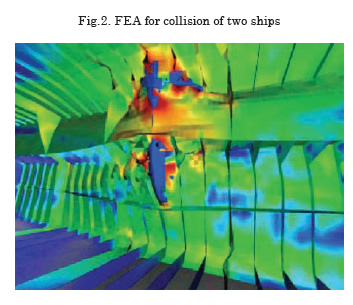
Until 1998, the SOLAS regulations on subdivision and damage stability specified damage stability requirements only for cargo ships longer than 100 meters. Since 1998, this limit has been lowered to 80 m for new cargo ships. Additional transverse bulkheads to fulfil damage stability requirements are costly and restrict operations. However, the new SOLAS regulations permit for some ships alternative arrangements, provided that at least the “same degree of safety” is achieved. This notation allows some flexibility of structural designs supported by advanced simulations. E.g. a structural design having increased collision resistance thus reducing the probability of penetration of the inner hull could eliminate the need for additional bulkheads. Based on extensive FEA simulations for ship collisions, Germanischer Lloyd developed an approval procedure which provides the first such standard for evaluation and approval of alternative solutions for design and construction of these ships, Fig.2, Zhang et al. (2004). The basic philosophy of the approval procedure is to compare the critical deformation energy in case of side collision of a strengthened structural design to that of a reference design complying with the damage stability requirement described in the SOLAS regulation.
Finite-element analyses (FEA) require load specifications which for ships involve frequently external hydrostatic and hydrodynamic loads.
GL.ShipLoad, Cabos et al. (2006), supports efficient load generation for global FEA of ship structures. Hydrostatic and hydrodynamic computations are integrated into the program. GL.ShipLoad supports the generation of loads from first principles (realistic inertia and wave loads for user supplied wave parameters), but the program also aids in the selection of relevant wave situations for the global strength assessment based on bending moments and shear forces according to Germanischer Lloyd’s rules. The result is a small number of balanced load cases that are sufficient for the dimensioning of the hull structure.
Vibration analyses
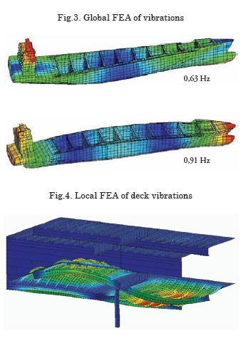
Advances in computer methods have made 3-d FEA today the standard choice for ship vibration analyses, Asmussen and Mumm (2001). The computations require longitudinal mass and stiffness distribution as input. The mass distribution considers the ship, the cargo and the hydrodynamic 'added' mass, Fig.3. The added mass reflects the effect of the surrounding water and depends on the frequency. One can either use estimates based on experience or employ sophisticated hydrodynamic simulations. For local vibrations analyses, Fig.4, added mass needs to be considered if the structures border on tanks or the outer hull plating. Because of the high natural frequencies of local structures, FEA models must be detailed including also the bending stiffness of structural elements.
Acoustics
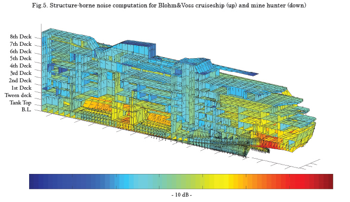
For very high frequencies (structure-borne noise), the standard FEA approach to vibration analyses is impossible due to excessive computational requirements. For a typical passenger vessel for a frequency of 1000 Hz, a FEA vibration model would lead to several million degrees of freedom. However, the very fact that information is required only averaged over a frequency band allows an alternative, far more efficient approach based on statistical energy analysis (SEA). The Noise Finite Element Method (GL NoiseFEM) of Germanischer Lloyd, Cabos and Jokat (1998), Cabos et al. (2001), is based on a related approach. GL NoiseFEM predicts the propagation of noise by analyzing the exchange of energy between weakly coupled subsystems. Validation with full-scale measurements shows that the accuracy of GL NoiseFEM is sufficient for typical structure-borne sound predictions for the frequency range between 80 Hz and 4000 Hz, Wilken et al. (2004). While further development is still needed, structure-borne noise analyses have been validated with good agreement on the wetted shell. Reliable prediction of the structure-borne noise is an important step towards predicting radiated noise of vessels. In the meantime, GL NoiseFEM structure-borne noise analyses are already applied to support the design of navy ships, cruiseships and customer-made yachts, Fig.5.
Computational Fluid Dynamics (CFD)
Seakeeping
For many seakeeping issues, linear analyses (assuming small wave height or small wave steepness) are appropriate and frequently applied due to their efficiency. The advantage of this approach is that it is very fast and allows thus the investigation of many parameters (frequency, wave direction, ship speed, metacentric height, etc.). Non-linear computations employing time-domain approaches are usually necessary for the treatment of extreme motions. These simulations require massive computer resources and allow only the simulation of relative short periods (seconds to minutes).
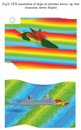
Combining intelligently linear frequency-domain methods with nonlinear time-domain simulations allows exploiting the respective strengths of each approach, El Moctar (2005). The approach starts with a linear analysis to identify the most critical parameter combination for a ship response. Then a non-linear CFD (Computational Fluid Dynamics) analyses determines motions, loads and free surface (green water on deck). We employ the commercial RANSE solver Comet for our purposes, e.g. Fig.6.
Fluid-structure interaction is a topic of increasing importance in our experience. In a weak coupling, the computed pressures from the seakeeping analyses are used to compute the structural response to these forces. In a strong coupling, the hydrodynamic and the structural problem are solved simultaneously. The hydrodynamic model then considers the deformation of the hull, the structural model the loads from the hydrodynamics, Oberhagemann et al. (2008).
Rudder flows
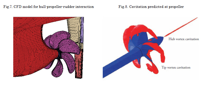
CFD is the most appropriate tool to support practical rudder design, Fig.7 (see page 12). The propeller is typically modelled in a simplified way using external forces distributed over the cells which cover the location where the propeller would be in reality. The sum of all axial body forces is the thrust. The body forces are assumed to vary in radial direction of the propeller only. This procedure is much faster than geometrical modelling of the propeller (by two orders of magnitude) at a negligible penalty in accuracy (about 1%). The procedure has been extensively validated for rudder flows both with and with-out propeller modelling. The same approach for propeller and rudder interaction can be applied for podded drives, Junglewitz and El Moctar (2004). Comet allows also the treatment of cavitating flows, Fig.8 (see page 12). The extensive experience gathered in the last 5 years has resulted in a GL guideline for rudder design procedures, GL (2005), El Moctar (2007).
HVAC and fire simulations
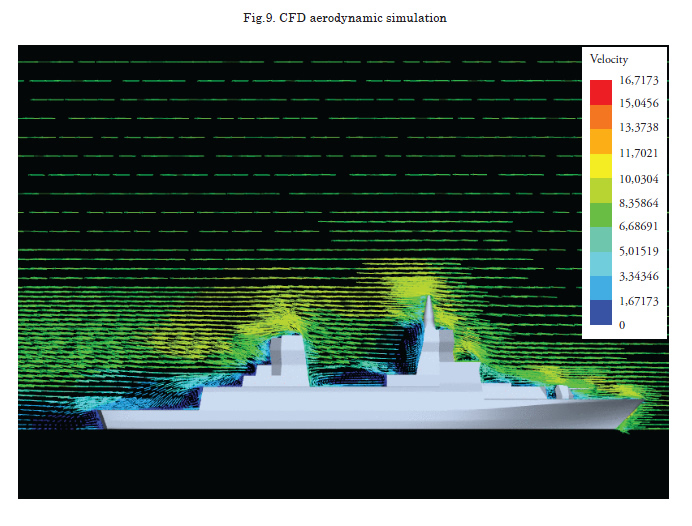
Aerodynamic flows around ship superstructures can be computed by CFD, Fig.9, although wind tunnel tests still are popular and widely used. CFD offers the advantage of overcoming scale effects which can be significant if thermodynamic processes are involved, El Moctar and Bertram (2002). HVAC (heat, ventilation, air condition) simulations involve the simultaneous solution of fluid mechanics equations and thermodynamic balances, often involving concentrations of different gases. Navy applications include for example the smoke and heat (buoyancy and turbulence) conditions on helicopter decks affecting safe helicopter operation.
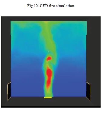
At present, zone models and CFD tools are considered for fire simulations in ships. Zone models are suitable for examining more complex, time-dependent scenarios involving multiple compartments and levels, but numerical stability can be a problem for scenarios involving multi-level ship domains, HVAC systems and for post-flashover conditions. CFD models can yield detailed information about temperatures, heat fluxes, and species concentrations, Fig.10. However, the time penalty of this approach currently makes CFD unfeasible for long periods of real time or for large computational domains. Nevertheless, applications have graduated from preliminary validation studies to more complex applications for typical ship rooms (accommodation, atrium, engine room), Bertram et al. (2004).
Evacuation simulation
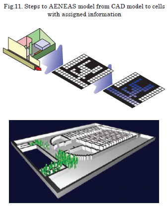
Evacuation assessment became a major topic at the International Maritime Organization (IMO) after the loss of the ‘Estonia’, resulting in new requirements for evacuation analyses in an early stage of the design process, IMO (2002). Germanischer Lloyd and TraffGo have developed the software AENEAS for this purpose. Evacuation analyses focus on safety, but the tool can be used also for the optimization of boarding and de-boarding processes, Petersen et al. (2003), or space requirements for promenades on cruise ships and large RoPax ferries. These simulations are very fast, allowing typically 500 simulations within one hour, to gain a broad basis for statistical evaluation. The ship is represented by a simplified grid of different cell types (accessible floor, doors, stairs, obstacles/walls), Fig.11. Passengers and crew are represented by intelligent agents. The same approach can be used to simulate crew movement on board of navy ships, e.g. time to man battle stations.
Germanischer Lloyd has developed an integrated methodology called NESTOR, Petersen and Voelker (2003), combining fire simulations with the Multi Room Fire Code, evacuation simulation with AENEAS and an Event Tree Analysis for risk assessment. Meyer-König et al. (2005) coupled seakeeping simulations and evacuation simulations in a semi-empirical approach to find the influence of ship motions on evacuation times. Since trim and pitch angles are usually relatively small, their effect is mostly negligible. Roll motions were found to be less critical than static heel for evacuation time.
Final remark
The technological progress is rapid, both for hardware and software. Simulations for numerous applications now often aid decisions, sometimes ‘just’ for qualitative ranking of solutions, sometimes for quantitative ‘optimization’ of advanced engineering solutions. Continued validation feedback serves to improve simulation tools as well as it serves to build confidence.
However, advanced simulation software alone is not enough. Engineering is more than ever the art of modelling, finding the right balance between level of detail and resources (time, man-power). This modelling often requires intelligence and considerable (collective) experience. The true value offered by advanced engineering service providers lies thus not in software licenses or hardware, but in the symbiosis of highly skilled staff and these resources.
Acknowledgements
Many colleagues at Germanischer Lloyd have supported this paper with their special expertise, supplying text and/or figures, namely (in alphabetical order) Christian Cabos, Bettar El Moctar, Jürgen Jokat, Axel Köhlmoos, Holger Mumm, Stefan Nusser, Ulf Petersen, Helge Rathje, Pierre Sames, Tobias Zorn.
References
ASMUSSEN, I.; MUMM, H. Ship vibration, GL technology, Germanischer Lloyd, Hamburg, http://www.gl-group.com/brochurepdf/0E094.pdf. 2001.
BERTRAM, V.; COUSER, P. CFD possibilities and practice, The Naval Architect, September 2007, pp.137-147 2007.
BERTRAM, V.; EL MOCTAR, O.M.; JUNALIK, B.; NUSSER, S. Fire and ventilation simulations for ship compartments, 4th Int. Conf. High-Performance Marine Vehicles (HIPER), Rome, pp.5-17. 2004.
CABOS, C.; EISEN, H.; KRÖMER, M. GL.ShipLoad: An Integrated Load Generation Tool for FE Analysis, 5th Int. Conf. Computer and IT Applications to the Maritime Industries, Leiden, www.compit.info. 2006.
CABOS, C.; JOKAT, J. Computation of structure-borne noise propagation in ship structures using noise-FEM, 7th Int. Symp. Practical Design of Ships and Mobile Units (PRADS), The Hague, pp.927-934. 1998.
CABOS, C.; WORMS, C.; JOKAT, J. Application of an energy finite element method to the prediction of structure borne sound propagation in ships, Int. Congr. Noise Control Engineering, The Hague. 2001.
EL MOCTAR, O.M. Computation of slamming and global loads for structural design using RANSE, 8th Num. Towing Tank Symp. (NuTTS), Varna. 2005.
EL MOCTAR, O.M. How to avoid or minimize rudder cavitation, 10th Num. Towing Tank Symp. (NuTTS), Hamburg. 2007.
EL MOCTAR, O.M.; BERTRAM, V. Computation of viscous flow around fast ship superstructures, 24th Symp. Naval Hydrodyn., Fukuoka. 2002.
FACH, K.; BERTRAM, V. High-performance simulations for high-performance ships, 5th Int. Conf. High-Performance Marine Vehicles (HIPER), Launceston, 2006, pp.455-465. 2006.
GL. Recommendations for preventive measures to avoid or minimize rudder cavitation, Germanischer Lloyd, Hamburg. 2005.
IMO. Interim guidelines for evacuation analyses for new and existing passenger craft, MSC/Circ.1033, International Maritime Organization 2002.
JUNGLEWITZ, A.; EL MOCTAR, O.M. Numerical analysis of the steering capability of a podded drive, Ship Technology Research 51/3, pp.134-145. 2004.
MEYER-KÖNIG, T.; VALANTO, P.; POVEL, D. Implementing ship motion in AENEAS - Model development and first results, 3rd Int. Conf. Pedestrian and Evacuation Dynamics, Vienna. 2005.
OBERHAGEMANN, J.; EL MOCTAR, O.; HOLTMANN, M.; SCHELLIN, T.; BERTRAM, V.; KIM, D.W. Numerical simulation of stern slamming and whipping, 11th Numerical Towing Tank Symp., Brest. 2008.
PETERSEN, U.; MEYER-KÖNIG, T.; POVEL, D. Optimising boarding and de-boarding processes with AENEAS, 7th Int. Conf. Fast Sea Transportation FAST, Ischia, pp.9-16. 2003.
PETERSEN, U.; VOELKER, J. Deviating from the rules – ways to demonstrate an equiva¬lent level of safety, World Maritime Technology Conf., San Francisco. 2003.
WILKEN, M.; CABOS, C.; SEMRAU, S.; WORMS, C.; JOKAT, J. Prediction and measurement of structure-borne sound propagation in a full scale deckhouse-mock-up, 9th Int. Symp. Practical Design of Ships and Mobile Units (PRADS), Lübeck-Travemünde, pp.653-659. 2004.
ZHANG, L.; EGGE, E.D.; BRUHNS, H. Approval procedure concept for alternative arrangements, 3rd Int. Conf. Collision and Grounding of Ships (ICCGS), Tokyo, pp. 87-96. 2004.