Ship Science & Technology - Vol. 14 - n.° 27 - (67-73) July 2020 - Cartagena (Colombia)
DOI: https://doi.org/10.25043/19098642.206
Juan Sebastián Lugo Pinilla 1
1 Ingeniero Mecánico — Ingeniero Industrial. Flotilla de Submarinos del Caribe. Cartagena, Colombia. Email: Juan.lugo.p@armada.mil.co
Date Received: March 25th 2020 - Fecha de recepción: Marzo 25 de 2020
Date Accepted: July 7th 2020 - Fecha de aceptación: Julio 7 de 2020
Through the corrective maintenance process of a bearing, regardless of its origin, certain anomalies related to its main elements, due to the condition of the type of maintenance, are expected. This was the case of the jib crane of the Caribbean Submarine fleet, used mainly to load the wiring and charging sockets for the supply of electrical energy to the Submarines. During a routine operation, it malfunctioned and stopped working without warning. An inspection was carried out in which corrective maintenance was deemed necessary, it was at the time that the bearing support was uncovered and its advanced state of deterioration was observed. Being this the main failure, and through application of engineering principles and simulation software, the reason for the deterioration was determined, and the optimal bearings for the correct operation of the jib crane were selected.
Key words: Jib crane; Structure; Bearing, Simulation
Durante el proceso de mantenimiento correctivo de un rodamiento, independiente de su origen, se espera encontrar ciertas anomalías relacionadas con sus elementos principales, esto debido a la condición del tipo de mantenimiento. Este fue el caso del brazo de carga de la Flotilla de Submarinos del Caribe, utilizado principalmente para cargar el cableado y la toma de carga en el suministro de energía eléctrica a los Submarinos. Durante una operación rutinaria presentó fallas y dejó de funcionar sin dar previo aviso. Se llevó a cabo una inspección en la que se determinó que era necesario realizar un mantenimiento correctivo, fue en el momento en que se destapó el soporte de los rodamientos que se evidencio el avanzado estado de deterioro de estos, siendo esta la falla principal y mediante aplicación de los principios de ingeniería y software de simulación, se logró determinar la razón del deterioro y seleccionar los rodamientos óptimos para el correcto funcionamiento del brazo de carga.
Palabras claves: Brazo de carga; Estructura; Rodamiento, Simulación.
The jib crane was built in the year 2017, it is defined as a structural element designed to load the wiring and the charging socket of the submarines; it is operated by a control panel, with 8 buttons that control 4 motors. This, with the main purpose of charging the batteries of the submarine with the required external current. This system must comply with 4 degrees of freedom that allow the operator to precisely transport the required components.
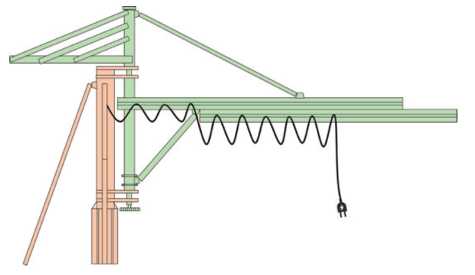
This mechanical structure seen in Fig. 1 is divided into two parts, the fixed part (red color) and the mobile part (green color). The latter, consists of 7 elements: the load socket, wiring, rotation axis, a tray with the counterweights, a main beam, an upper support and a lower support, with a total 3997 kg weight, which in turn rotates on a bushing located in the upper support and two bearings located in the lower support, which will be explained later. Fig. 1 shows the axis of rotation as the element that connects the seven elements mentioned above, with the anchoring of the spring through a mast and six diagonal supports, called the fixed part.
Fig. 1. Structure ofthejib crane.
Source: Authors.
The movement of the jib crane is provided by four motors located along its moving part. The main one is parallel to the mast and works by means of a chain that allows for orientation movement, in the horizontal plane, with a restriction of 180° at no more than 5 rpm; the other motors are located on the main beam and provide for the movement of translation of the beam, translation of the hoist motor through the beam and lifting of the load socket. In its fullness they allow it to move according to operation specifications.
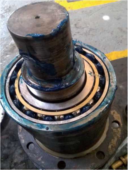
Recently, the jib crane began to malfunction in its orientation movement, apparently due to the low efficiency of the main motor, forcing the operator to provide manual support to complete the objective. After inspection, disassembly, and verification of electrical elements such as motors, wiring and control panel, it was determined that was a mechanical failure that would most likely be in the shaft. After disassembly, during the bearings inspection, it was found that, due to their deteriorated condition, the suitability of these elements for this application needed to be recalculated in order to comply with the design parameters or a solution that would provide greater reliability to the design had to be found.
At the top of the bearing housing there was a tapered roller bearing and at the bottom of the housing there was a single row ball bearing with angular contact, as shown in Fig.2 and Fig.3 respectively. According to the technical specifications both elements meet the design criteria. However, commercially there are other options that allow for optimizing the equipment, while minimizing wear and extending its useful life, such as a single row ball bearing with angular contact or a deep groove ball bearing.
Fig. 2. Upper bearing of the jib crane bracket.
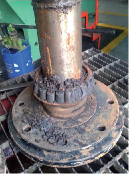
Source: Authors.
Fig. 3. Lower bearing of the jib crane bracket.
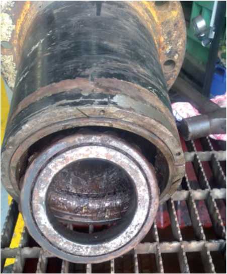
Source: Authors.
Likewise, the evidence of wear at the ends of the metal part as shown in Fig. 4, indicated the need for machining the bearing housing to eliminate the existing wear, in addition to a proposal for bearing selection through simulation based on loads and calculations of support reactions to determine the forces applied.
Fig. 4. Wear found at the base of the lower bearing.
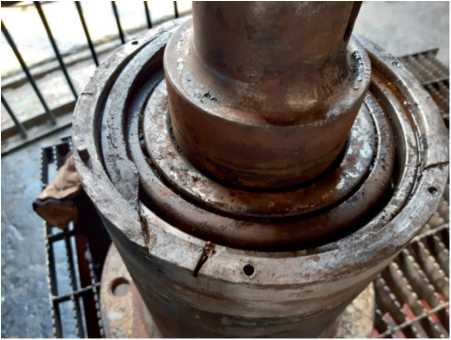
Source: Authors.
Bearings are objects designed to keep their moving parts in the proper position, decrease friction and facilitate movement. They can support axial loads or loads in the direction of the axis, tangential or perpendicular loads to the direction of the axis and combined loads. [4]
They generally consist of two rings or discs with raceways, rolling elements and a structure that keeps the rolling elements and the guides separate, called a cage. [2]
According to the SKF bearing selection manual, there are different types of bearings with characteristics that make them suitable for some applications more than others. Cylindrical roller bearings can support higher radial loads compared to a deep groove ball bearing, spherical ball bearings can allow a greater degree of freedom to the shaft, etc. Other types of bearings include spherical roller bearings, single direction thrust ball bearings, needle roller bearings, which are widely used in small spaces, and tapered roller bearings, among others. [2]
The arrangement of the bearings is very important in its properties, they can be oriented face to face or in "X" configuration, back to back or "O" configuration, and finally, in tandem. Again, each configuration increases or decreases the properties of the bearing as required. In the specific case of the jib crane, as can be seen in Fig. 5., the lower support consists of two bearings separated at a distance of 200 mm and crossed by a 100 mm diameter shaft in a 180 mm support.
Fig. 5. Isometric section view of the lower jib crane support.
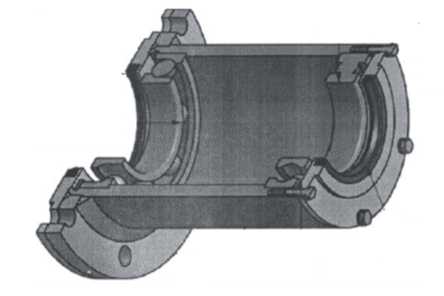
Source: Authors.
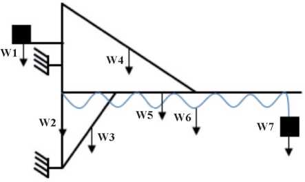
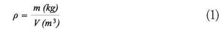
Starting the calculation phase to determine the arm loads on the bearings, it was necessary to separate the components as shown in Fig. 6, estimating the weights of some of the objects, considering that the design drawings did not include this data, and others simply do not have any drawings. For this we used the expression (1) or density formula. The counterweights were the easiest, since their volume was the only variable requiring identification (that of a rectangular prism) and the density formula of the object was used to clear its weight. In the case of more complex objects, such as the tray where the counterweights are supported, the task was more interesting, since it was necessary to divide the structure in geometric figures of known volume and add them together to use the same formula mentioned above. Other elements had the weights in the design drawings.
Fig. 6. Structural components ofthejib crane.
Source: Authors.
For the steel parts a density (p) of 7850 kg/m3 was used, and for the counterweights specifically 2400 kg/m3. [1]
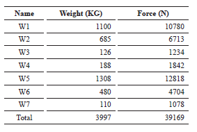
In this way the approximate weight of the structure was obtained (see Table 1) and from this data, the exercise was worked as a structure supported by two supports on which there will be some reactions or forces contrary to the forces exerted by the weights.
Table 1. Weight of the components.
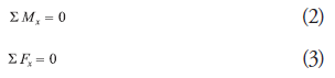
In order to get the reactions of the components of the jib crane, it was imperative to calculate the distances, so by means of the equations of moments (2) and forces (3), the desired result was achieved. [1].
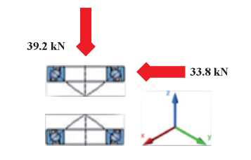
Due to the working conditions of the jib crane, emphasis was placed on the most critical case, consisting of the fully extended arm and the charging socket at the opposite end of the axis, simulating the position of the jib crane during powering of an underwater unit. Based on the traditional free body diagram, where the reactions in the supports are found, and with the help of the tool "Bearing select" of the company SKF [3], together with the existing design parameters and dimensional restrictions, a simulation was recreated to provide the optimal type of bearing to be installed in the lower support of the jib crane.
To begin the simulation, the concrete cases that complied with the established design dimensions (internal and external diameters and width of the bearing) and available in the SKF simulator were established, and directed towards five alternatives.
* Due to the condition of being a rigid ball bearing, the simulation in face to face or back to back position are equivalent.
The following parameters were considered to determine the optimal solution
Below is a description of the different parameters to be considered. The static safety coefficient, for example, allows the designer to have certain tolerance in case the operator or owner decides to vary the loads of the component without running the risk of damaging the bearings by such movements. The basic dynamic load rating is the load whose magnitude and direction are constant and under which the bearing reaches the nominal life of one million turns [2]. The lubrication interval is very important since the bearings are sealed and the structure must be dismantled to perform this operation. The minimum load is an operating restriction that indicates if the existing weight is in accordance with the bearing or is below it to exert the necessary pressure for operation. A bearing that exceeds the requirements is not desirable, since it would be assumed that the structure is over-dimensioned, affecting its functionality and efficiency.
The bearings selected for the simulations were:
Results and Analysis
The axial and radial reactions were determined by the sum of moments and forces, resulting in 39.2 kN and 33.8 kN respectively (see Fig 7). This data was required by the tool "Bearing select" of the company SKF to start the simulation work.
Fig. 7. Location of reactions in the bearings.
Source: Authors.
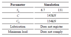
The simulation was not possible since the simulator does not allow such a configuration between different bearing classes, and this specific case includes a tapered roller bearing together with a single-row ball bearing with angular contact.
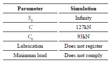
The parameters described in Table 2 show that the static safety factor tends to be infinite, it does not register any lubrication interval and does not meet the minimum load established in the design.
Table 2. Result ofthe simulation case 2.
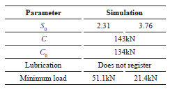
The parameters described in Table 3 show that the static safety factor varies according to the location of the bearing, with the S0 of the upper bearing 2.31 and the lower bearing 3.76, as well as, a minimum load of 51.1 kN and 21.4 kN respectively. No lubrication interval is recorded.
Table 3. Result of the simulation case 3.
It records values for all variables, so it is shown as an eligible alternative.
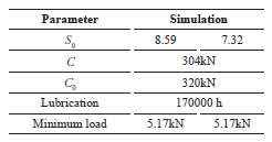
Table 4. Result of the simulation case 4.
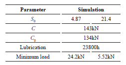
Table 5. Result of the simulation case 5.
The parameters described in Table 6 show that it does not register a lubrication interval and does not comply with the minimum load established in the design.
Table 6. Result ofthe simulation case 6.
Cases 4 and 5 were the only ones that met the requirements outlined above. Analyzing these bearings more closely, it should be noted that the static safety factor of the upper bearing is lower for case 4 and the opposite case for case 5, similar to the tapered roller bearings, where the loads are distributed equally between the two bearings, while in the angular contact ball bearing, the loads are mostly assumed by the upper bearing. This data can be directly related to the minimum load required in each location, as seen in case 5, where they are equal, as opposed to case 4, where the load for the upper bearing is almost five times the load of the lower one.
It was expected that due to the high basic dynamic and static load capacities of the tapered roller bearing, its lubrication time would be so long. However, according to the SKF bearing manual it is unreliable to have a lubrication time longer than 30,000 hours [2].
Finally, since price is one of the fundamental parameters for the decision to change the bearings of the jib crane, it is not a relevant factor in this case, since the cost of the project in general, is significantly higher than the cost of the bearings. However, if a bad decision is made, it can lead to reprocessing, which increases project costs and decreases equipment availability.
Considering the results of the simulations of the cases studied, the recommendations of the SKF company and the calculations made, it was concluded that the bearings to be selected are those of angular contact ball 7220 BECBP in a back-to-back arrangement, as indeed it was done and installed. The current state of the support with the bearings installed can be seen in Fig.8.
Fig. 8. Lowerjib crane support after maintenance.
Source: Authors.
It was very helpful to have the support of the Engineers and Technicians of the Corporación de Ciencia y Tecnología para el desarrollo de la Industria Naval, Marítima y Fluvial (COTECMAR) who showed their expertise to take on the challenge of performing the first maintenance of the jib crane in the main dock of the Caribbean Submarine Fleet and finish the project successfully.
[1] BEER, F., JOHNSTON, E. AND CORNWELL "Vector Mechanics for Engineers,"2010.
[2] SKF “Rodamientos” October 2015 [Online]. Available: https://www.skf.com/co
[3] SKF “Bearing select” October 2015 [Online]. Available: https://www.skf.com/co/support/engineering-tools/skf-plain-bearing-calculator [Accessed 4 August 2020].
[4] SENA “Mantenimiento de rodamientos y cojinetes” March 1995 [Online]. Available: https://repositorio.sena.edu.co/bitstream/handle/11404/765/mantenimiento_rodamientos_cojinetes.pdf;jsessionid=4DDB6D38F5638DEE5C8AD65B03A4E4B7?sequence=1 [Accessed 4 August 2020].