Ship Science & Technology - Vol. 14 - n.° 27 - (55-66) July 2020 - Cartagena (Colombia)
DOI https://doi.org/10.25043/19098642.205
Hugo Leonardo Murcia Gallo1
Richard Lionel Luco Salman2
David Ignacio Fuentes Montaña3
1 Escuela Naval de Cadetes “Almirante Padilla”, Colombia. Email: hugonavy@gmail.com
2 Instituto de Cs. Navales y Marítimas, Universidad Austral de Chile. Valdivia, Chile. Email: rluco@uach.cl
3 Universidad Técnica de Berlín, Alemania. Email: fuentes@campus.tu-berlin.de
Date Received: January 30th 2020 - Fecha de recepción: Enero 30 de 2020
Date Accepted: June 13th 2020 -Fecha de aceptación: Junio 30 de 2020
The main objective of this study is to analyze the structural response of a boat during a slamming event using the Finite Element Method in a Small Water Area Twin Hull (SWATH) type boat. In the mentioned load condition, the acceptance criteria established by a classification society must be fulfilled, taking into account the areas where this event affects the structure such as the junction deck, the pontoons and other structural members established by the standard, all this generated by the high pressure loads in the ship's structure in a very short period of time being an element of study in this type of vessels, as long as they are within the range of high speed vessels. Among the main results of this study were the deformations and stresses in the structure obtained under the reference parameters of the classification society [1].
Key words: Ship, Boat, Mechanical Model, Finite Element Method, Structure, SWATH.
El objetivo principal de este estudio, es analizar la respuesta estructural de una embarcación en el evento del Slamming utilizando el Método de Elementos Finitos en una Embarcación tipo Small Water Area Twin Hull (SWATH). En la mencionada condición de carga se deben cumplir con los criterios de aceptación establecidos por una sociedad clasificadora, teniendo en cuenta las áreas donde este evento incide en la estructura como lo es la cubierta de unión, los pontones y demás miembros estructurales establecidos por la norma, todo esto generado por las altas cargas de presión en la estructura del buque en muy corto espacio de tiempo siendo un elemento de estudio en este tipo de embarcaciones, siempre y cuando estén dentro del rango de embarcaciones de alta velocidad. Dentro de los principales resultados de este estudio se obtuvieron las deformaciones y esfuerzos en la estructura bajo los parámetros de referencia de la sociedad clasificadora [1].
Palabras claves: Buque, Embarcación, Modelo Mecánico, Método de Elementos Finitos, Estructura, SWATH.
The use of the Finite Element Method (hereinafter FEM) is a tool that allows to analyze and evaluate both the stresses and deformations that occurs in an element of study as a response of a load on it. This allows the Naval Design and Engineering area to perform evaluations of elements of a system, which in the case of this study, simulates the response of the structure and generates a tool for the designer to analyze the overall vessel under slamming pressures.
In this way, the aim is that the vessel to be designed complies with the requirements established in the classification regulations ensuring the structural integrity of the vessel during its life cycle in the Operation Phase. While it is true that the rules of the various classification societies are guidelines for design, these aim for the structure to support the conditions of the ocean it will face, and generates as a result the dimensions of the structural elements and all those elements that contribute to the structural integrity of the boat.
The vessel in this study was designed to comply with particular performance specifications such as speed, length and beam dimensions, for which the shapes were carried out through the use of design tools (CAD) and analysis (CAE) (Computer Aided Design- Computer Aided Engineering). This was an input in the subsequent implementation of structural analysis by the Finite Element Method with the use of numerical modeling. The process integrates the basic knowledge of surface handling and is complemented with the application of the different loads that affect the case study such as Slamming in the Wet Deck and Hull, Hydrostatic Pressure, Gravity and the Displacement of the Vessel. Within the development of this study, the mesh sensitivity analysis was carried out, which ensures the independence of the results of the mesh.
Due to the above, and in view of the fact that FEM allows the analysis of irregular geometries such as the hull of a vessel, the application of loads, the handling of the system's boundary conditions and the numerical evaluation of the materials' behavior, it can be established that it is a convenient tool to carry out the analysis of the present investigation and to observe the response of the vessel's structure.
Currently, FEM is applied to different areas of knowledge, thus becoming a functional tool for the development of any research, validation or evaluation of a physical phenomenon. Within the applications that are most used in engineering processes, we find the analysis and evaluation that allows to determine the field of displacements, deformations, stresses in any element of the system, frequency, resistance, rigidity and fatigue among others. With which, it is possible to analyze and evaluate through a study if the conditions in which a future project can become feasible from an initial design stage and make decisions that reduce time and decrease the costs associated with an engineering design and construction process.
Based on the above and in view of the evaluation and analysis capabilities of FEM which allows to analyze the mechanical behavior in a linear, nonlinear, static or dynamic way, the Naval Industry has developed the validation of its projects in the preliminary and contractual design stage with the use of these computational tools. In this way, and given the current conditions of competition in the Shipyard environment and their Design Offices, the use of FEM is a tool for the development of their activities of criteria testing and cost reduction in the Industry, with this, being able to analyze if the results obtained are acceptable against the established acceptance criteria and the products should be marketed.
An example of this application is found in the work of Numerical and Experimental Validation of Bending in a Resin Steel Sandwich Structure for bulkheads and structural members, where the real behavior is compared with the numerical one and allows according to the authors to observe the behavior curve of the material and the process of failure and subsequent cracking [4]. In the same way, in other studies observed, structures and plates of any vessel in composite material are evaluated and allow to validate the results generated by the FEM, such as the specific case of the experimental and numerical flexion analysis of steel/resin sandwich material, which looked for to confront the real results with the FEM. The result is that both are similar and arriving at the conclusion that validates any real analysis with the numerical one for the use of Bulkheads, Reinforcements or any primary member that is required in a vessel [5]in multi-hull type boats, in [6] a trimarantype vessel is designed, analyzed and optimized, scanned with different classification societies, the stress and deformation results are compared with each one and an overall reduction of the vessel's displacement is achieved.
Likewise, in [7] a SWATH type vessel, an analysis of the structure was carried out by means of FEM, with the purpose of comparing the response of the structure with transversal loads, as a reference in the use of numerical models that allow the evaluation of the real conditions of a vessel, demonstrating again, the viability of the use of the method.
For this study understanding the conditions in which the vessel would be found was fundamental, therefore, the study of the slamming event is important in understanding that it is a transitory load that affects the structure of the vessel in its operation, evaluating this throughout its entire structure and validating the calculations enhanced in the scantlings, is a fundamental tool for any design process and testing of any vessel, allowing with it to validate that the process is suitable and responds to the objective of the present study.
This process has shown that the structure supports the stresses and deformations allowed by the classification society, under real parameters that contribute to the knowledge of a design process and structural analysis of a SWATH type vessel and gives the possibility to perform other analyses in different load conditions where it is required to study elements globally or locally using the FEM.
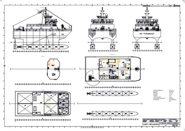
The vessel in this study has the general characteristics described in Table 1 and was designed as shown in the General Arrangement Plan Fig. 1, its mission profile is based on carrying out patrol operations in the Colombian Caribbean Island area, where the average wave height ranges from 1 meter to 5.56 meters according to statistics provided by the General Maritime Directorate [8] Table 1.
Fig. 1. General Arrangement Plan ARC ’’Yurumangui”.
Source: Authors
Tabla 1. Vessel characteristics
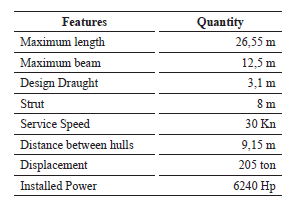
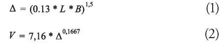
The previously described design is characterized under the displacement and speed standards for high speed craft, or HSC, where it states that it cannot displace more than 243.55 tons and must have a speed greater than 17.38 knots according to equations 1 and 2 [9].
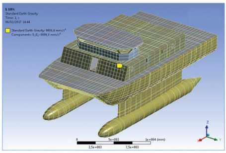
During the development of the analysis, the recommendations of the mentioned classification society were followed, for the application of the forces that act in the hull of the ship, which were divided in three different forces, characterizing the Hydrostatic Pressure with the design draught under full load (Fig. 2), the pressure during the Slamming event and the standard acceleration due to gravity, Fig. 3 [10].
Fig. 2. Hydrostatic pressure in the hull depending on the design draught.
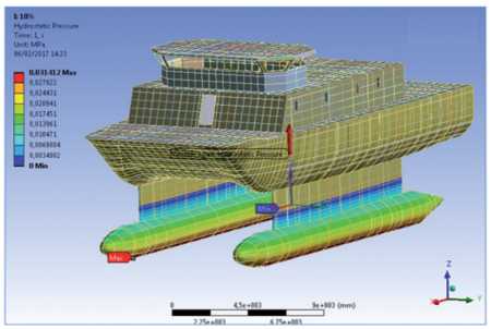
Source: Authors
Source: Authors
In this study, the effect of slamming on the structure of the boat is analyzed. [11] This effect are the pressure loads generated by the impact of the boat with the waves in short periods. Therefore, the classification society proposes as an acceptance criterion an stress value not higher than 125 MPa [10].
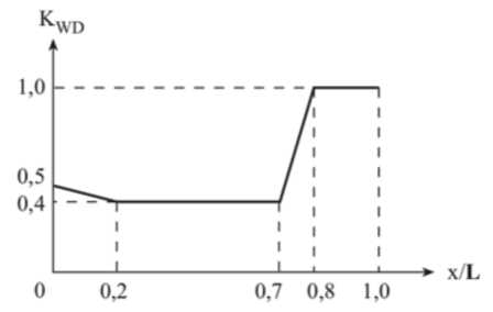
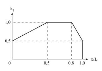
The results for the slamming load on the structure, bending moment, accelerations and others, were obtained by using the classificiation rules and construction, special vessels section 3 C 3.5.2 and C 3.5.3. of GL, which parameterize that they are a function of the dimensions of the vessel and, in the case of slamming, vary according to the length of the vessel as shown in Figs. 4 and 6.
Fig. 4. Slamming on Wet Cover.
Source: Authors
Fig. 5. Slamming Pressure on Wet Cover.
Source: Authors
Source: Germanischer Lloyd
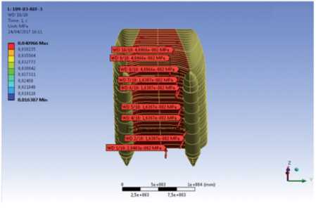
Fig. 7. Slamming pressure on the submerged hull.
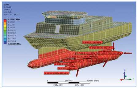
Source: Authors
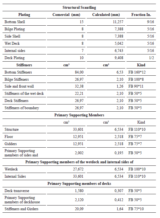
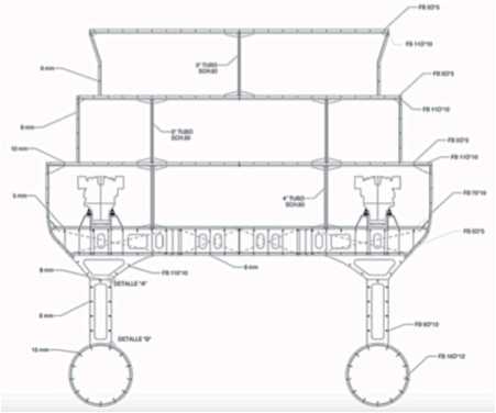
The Craft Scantling process can be seen in Figure 8 and was based on the GL classification rules, calculating the primary structural elements according to table No. 2 and Fig. 9 shows the midship section scantling drawing. For this study and for the characteristics of the patrol boat, aluminum 5083, density 2770 Kg/m3, Modulus of Elasticity 7.1 x 10¹⁰ Pa, Poisson's coefficient of 0.33, length not supported (le) 1200 mm and a space between longitudinal reinforcements (s) of 480 mm were selected as the material and parameters.
Fig. 8. SWATH Scanning Process Flowchart.
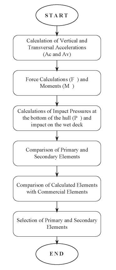
Source: Authors
Source: Authors
Source: Authors
The vessel was modeled and discretized using computer aided design software, thus modeling the hull shapes and structural elements. This process allows to materialize the project in order to export it to the finite element analysis software [12]. This allows for the analysis and observation of each of the members and their geometries so that they contribute to the structural rigidity and distribution of the loads applied to the boat [27].
For the analysis of this structure, several factors were considered: First, the selection of the type of element, which for the case study a Shell 181 element was selected for having four nodes and six degrees of freedom and admitting normal loads to its plane, bending loads, membrane loads and moments [27]. This is a tool that can analyze the Slamming loads in the structure, and giving priority to rectangular and not triangular elements, since normal displacements in the elements can occur and cause the nodes to not represent the physics of what is happening in the system, thus generating, possibly, errors. Secondly, the aspect ratio of the elements, which should predominate in values close to 1 in symmetry and allows for evaluating the physical effects that occur in the time period (Fig. 10). And thirdly, the quality of the elements (Fig. 11). All this, allows for the generation of the appropriate mesh, resulting in better analysis results. [13].
Fig. 10. Aspect ratio of the elements.
Element Metrics
In the process of generating the mesh, it was necessary to produce independent meshes for the structural members, which, due to their geometry, did not allow for the alignment of the nodes, thus achieving a correct distribution of the elements and allowing the analysis to be homogeneous with respect to the spatial distribution of the elements (Fig. 11). In order to ensure that the structure behaves as a single set, contact regions were established between the edges and faces of the different surfaces [14].
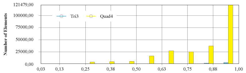
Fig. 11. Number of elements and their quality.
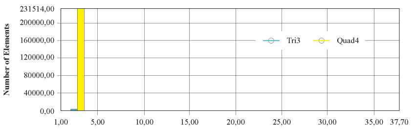
Element Metrics
Source: Authors.
In the generation of the mesh for the analysis of the loads in the structure of the ship, different refinements to the mesh were made (Table 3) in a global way for the hull, superstructure, primary and secondary members that contribute to the structural rigidity of the ship. This is a process of global and systematic refinement of the mesh that allows to determine that the results are independent of the density of the mesh. In this iterative process, it was possible to analyze and evaluate the quality of the elements and the independence of the results with reference to the density of the same. The relation of aspect of the elements in the different meshes, and the form of the elements were verified, obtaining as a result in the finest mesh, 210,300 rectangular type elements and 1,633 triangular elements, generating a percentage of 99.29% of rectangular elements.
Table 3. Project Mesh Characteristics.
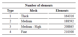
Source: Authors.
Based on the above, the quality of the elements is deemed adequate for the structure of the study obtaining a homogeneous mesh according to the proportions of the elements, having a density much higher than 50% (Fig. 12).
Fig. 12. Finite Element Model ofthe Study Vessel.
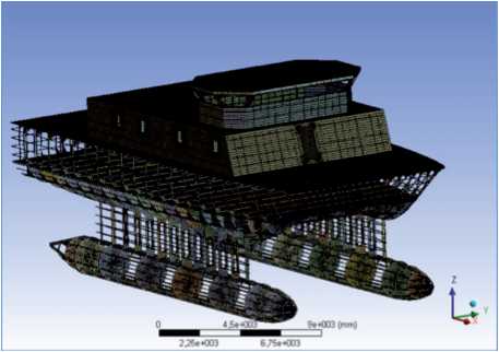
Source: Authors.
In the verification of the independence of the results with respect to the density of the mesh, in Table 4, the results of stress and deformation are presented. Finally, in Table 5 the percentage of change with respect to the previous refinement is shown. The change between mesh 2 and 3 is less than 2%, which allows us to conclude that the mesh with medium-high refinement is enough to obtain satisfactory results. However, mesh No. 4 was chosen, since it does not demand excessive computational resources, giving independence to the results with respect to the mesh.
Table 4. Stress and deformation.
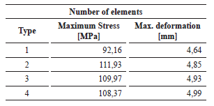
Source: Authors
Table 5. Mesh Sensitivity Analysis.
Source: Authors.
The physical phenomena that occur in the boat by the action of slamming load on the wet deck and hull, require a reliable result. It is necessary to evaluate the results of the stresses and deformations obtained and compare them with the acceptance criteria established by the GL classification society. As a condition for the system's contour, the inertial lightening function was used, which allows the system to be balanced, inducing fictitious loads that, for the case study, would be the Thrust Force, generating a static equilibrium [15] [16] [17].
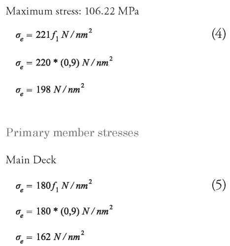
For the GL classifier, the stress acceptance criteria should not exceed 125 MPa according to Table C 3.2.1 of the GL classifier rules for welded aluminum alloy 5083. Therefore, the values should be lower in the structure.
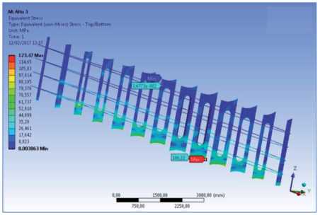
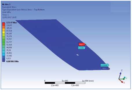
For the procedure, it becomes indispensable to use appropriate geometric shapes in the structural members that allow a homogeneous distribution of the stresses and reduce the points of concentration of stresses (Hard Points) in the development of the results. In this way, it was possible to for the stresses with the highest values to be found in the structures of the Naca profiles of the boat on the pontoons of the hull and the wet deck. This is in accordance with the distribution function of stresses in the hull by the action of the slamming load. In the case of the maximum deformation, it was shown in the wet deck in the sector of the bow with a value of 4.99 mm (Fig.14), and in the case of the maximum stress, it had a value of 108.37 MPa (Fig. 13) in the area of the structure in the Naca profiles that join the pontoon with the upper hull.
Fig. 13. MaximumVessel Stress 108.37 MPa.
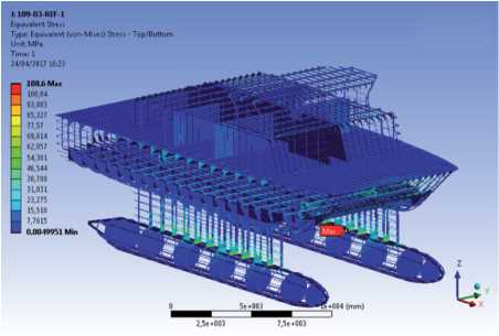
Source: Authors.
Fig. 14. Maximum Vessel Deformation 4.99 mm.
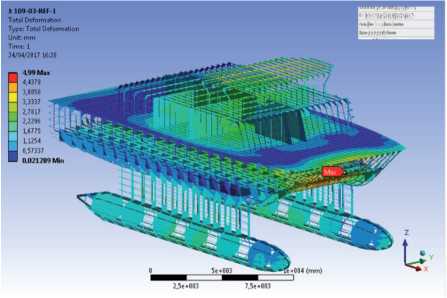
Source: Authors.
According to the classification rules for HSC type boats Part 3 Structures, Equipment, Chapter 3 Hull Design - Aluminum 2018, they cannot exceed the following permissible stresses and can be analyzed in three elements (Equations 3, 4 and 5) Sheets, Reinforcements and Primary Members, for which the validation of the results obtained in the area where the greatest stresses of the structure will be presented was made (Figs. 15, 16 and 17).
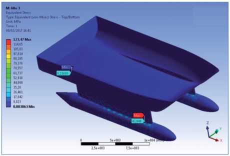
Source: Authors.
Fig. 16. Transverse Stress Pontoon Profile Structure.
Source: Authors.
Source: Authors.
Hull of the boat

Transverse reinforcement Naca profi le structure
From what was previously observed, it could be seen that the stresses on the structures was kept well below the maximum allowable stress presented by the Slamming event adequately under the parameters of the DNV GL classification society in a Conceptual Design stage.
The design and the results obtained, for the case study, comply with the criteria established by GL. This, as a result of the application of the loads to which the boat is submitted in its hull and the junction deck during the Slamming event, results in a structure that presents a maximum stress of 108.37 MPa and a maximum deformation of 4.99 mm, being 13.3% below the value characterized by GL. In future work, and to ensure the structural integrity of the ship, the events of Splitting Moment, Tortional Moment and/or any combination of the above should be analyzed.
The process developed in this study, obtained adequate results to the parameters established by the Classification society by means of the use of FEM and the integration of different computer tools, making it a reference for the application of this in any type of vessel for further study in the Slamming event, because it has allowed to evaluate the designed structure by means of the obtaining of the stresses and deformations, characterizing those structural members under superior stresses by the loads of the system and their structural response. The use of computational tools for modeling, allows to analyze, from initial stages, to the designs of any type of vessel, obtaining, in perspective, the possible failures of an engineering project, allowing for correction prior to construction of any structural optimization with the purpose of obtaining a functional design to satisfy the needs of the shipowner and the reduction of costs in a shipyard.
[1] H. EVANS, "Basic Design Concepts,"A.S.N.E. Journal, pp. 671-678, 1959.
[2] H. MURCIA, Application of the Finite Element Method in the Structural Analysis of a Swath-type Patrol Boat, Cartagena de Indias: Escuela Naval de Cadetes "Almirante Padilla",2017.
[3] GERMANISCHER LLOYD, Analysis Techniques, Hamburg: GL, 2013.
[4] P. Y. ARIANTO, A. ZUBAYDI, B. PISCESA Y TUSWAN., "Experimental and Numerical Bending Analysis of Steel/Resin-Talk Sandwich Material," IPTEK , pp. 123-128, 2019.
[5] E. ALTUNSARAY, D. ÜNSALAN, G. NEŞER, K. T. GÜRSEL Y M. TANEr, "A parametric study for static deflections of symmetrically laminated rectangular thin plates," Scientific Bulletin "Mircea cel Batran" Naval Academy, 2019.
[6] D. FUENTES , M. SALAS, G. TAMPIER Y C. TRONCOSO, Analysis and Design of Marine Structures - Guedes Soares & Shenoi, Londres , 2015.
[7] W. WU, B. LIU Y C. GUEDES, "Ultimate strength analysis of a SWATH ship subjected to transverse loads," Marine Structures, vol. 57, pp. 105-120, 2018.
[8] DIMAR, "Climatology of the Main Ports of the Colombian Caribbean: San Andres and Providencia," Dirección General Marítima Colombia, Cartagena, 2010.
[9] DNV GL, Rules for Classification High Speed and Light Craft, Part 1 General Regulations Chapter 2 Class Notations, Høvik: DNV GL, 2018.
[10] GERMANISHER LLOYD, "Classification and Construction Rules for High Speed Craft," GL, Hamburg, 2012.
[11] B. PHELPS, Determination of wave loads for Ship Structural Analysis, Melbourne Australian Departament of Defence, 1997.
[12] C. FELIPPA, Introduction to the Finite Element Method, Boulder: University of Colorado at Boulder., 2004.
[13] ANSYS, "Manual," ANSYS, 2012.
[14] T. KURKI, "Utilization of integrated design and mesh generation in ship design process," Rakenteiden Mekaniikka (Journal of Structural Mechanics) , pp. 129-139, 2010.
[15] M. COSTACHE Y G. JAGITE, "Global Strenght Analysis in Head Waves, for an Offshore Support Vessel," Asian Journal of Applied Science and Engineering, pp. 73-88, 26 septiembre 2014.
[16] L. LIAO, A Study of Inertia Relief Analysis, Denver, Colorado: ASME, 2011.
[17] DNV GL, Finite Element Analysis, Hamburg: DNV GL, 2015.
[18] A. MOLAND, Maritime Engineering Reference Book, Burlington: Elsevier, 2008, p. 46.
[19] J. BJORHUS, "Jonathan Turner, Airplane Engineer," The Seattle Times, 18 Octubre 1995.
[20] R. W. CLOUGH, "Original Formulation of the Finite Element Method," Finite Elements in Analysis and Design, pp. 89-101, 1990.
[21] J. H. ARGYRIS, Energy Theorems and Structural Analysis, New York: London Butterworths, 1955.
[22] M. M. Y.V. SATISH KUMAR, "Finite element analysis of ship structures using a new stiffened plate element," Ocean Research, vol. 22, pp. 361-374, 2000.
[23] P. PIALA Y T. KALINA, "Finite Element Method in Ship's Industry," Electronical Technical Journal od Technology, Engineering and Logistic in Transport, pp. 182-186, Diciembre 2010.
[24] D. SERVIS, G. VOUDOURIS, M. SAMUELIDES Y A. PAPANIKOLAOU, "Finite element modelling and strength analysis of hold No. 1 of bulk carriers," National Technical University Athens Magazine, 2004.
[25] A. B. TRICLAVILCA TENORIO, D. A. MESTANZA RODRIGUEZ AND F. F. RIVERA TIRADO, "Simulation of Numerical Systems through Finite Elements of a River Vessel," International Conference IDS 2013, July 17, 2013.
[26] J. F. USECHE, El Método de los Elementos Finitos en Mecánica de Sólidos: Conceptos y Formulación Basica, Cartagena: Universidad Tecnologica de Bolivar, 2006.
[27] S. KOS, D. BRČIĆ Y V. FRANČIĆ, "Comparative Analysis of Conventional And Swath Passenger Catamaran," Journal of Maritime Studies, 2009.
[28] M. SALAS, "Analysis of Mechanical Structures with the Finite Element Method," Author, Valdivia, 2014.
[29] D. SOURCES, Analysis and Structural Optimization of a multihull designed in Aluminum, Valdivia: Universidad Austral de Chile, 2014.
[30] J. T. CELIGÜETA LIZARZA, Método de los Elementos Finitos para el Análisis Estructural, San Sebastian: University of Navarra, 2011.
[31] J. E. HURTADO, Introduction to Structural Analysis by Finite Elements, Manizales: Universidad Nacional de Colombia, 2010.
[32] R. COURANT, "Variational Methods For the Solution of Problems of Equilibrium and Vibrations," Bulletin of the American Mathematical Society, 1949.