Edgar Mulford1, Jairo Cabrera2
Historically, different methodologies of experimental analysis of naval and oceanic structures oriented to the execution of controlled experimental tests in facilities capable of reproducing environmental conditions specific to their operating locations have been developed. These methodologies enable the efficient design of oceanic structures, the minimization of production costs and the generation of scientific knowledge. This article details the design of an experimental analysis methodology for semi-submersible offshore systems for deep and ultra-deep water fields, obtaining satisfactory results, and the validity of the procedure as an important contribution to the phases of semi-submersible platform design, a concept selected as appropriate for the areas of interest of the Colombian Caribbean.
Key words: Experimental analysis, offshore ocean structures, Semi-submersible, instrumentation, reduced scale model.
Históricamente se viene desarrollando diversas metodologías de análisis experimental de estructuras navales y oceánicas orientadas a la ejecución de ensayos experimentales controlados en instalaciones capaces de reproducir condiciones ambientales propias de sus localizaciones de operación. Estas metodologías posibilitan el diseño eficiente de estructuras oceánicas, la minimización de costos de producción y la generación de conocimiento científico. En este artículo se detalla el diseño de una metodología de análisis experimental de sistemas offshore tipo semi-sumergibles para campos en aguas profundas y ultra-profundas, obteniéndose resultados satisfactorios, y de validez del procedimiento como un aporte importante a las fases del diseño de plataformas tipo semi-sumergibles, concepto seleccionado como el apropiado para las áreas de interés del Caribe Colombiano.
Palabras claves: Análisis experimental, estructuras oceanicas offshore, Semi-sumergible, instrumentación, modelo en escala reducida.
The offshore industry, especially related to operations of exploration, extraction and production of oil and gas at sea, generates the need to have large oceanic structures. Colombia, as a developing country, is betting on the offshore oil industry through an aggressive exploration and production investment plan, focused mainly on increasing its reserves with new and renewed offshore exploration contracts.
This presents the need for investment in issues of technological development of the local industry through human capital, the adoption of technologies, creation of cooperation networks (university - industry - state) and increased infrastructure, among others.
In this scenario, it is especially important to strengthen local technological capabilities, encourage the transfer of knowledge and implement facilities such as tanks or experimental channels to evaluate operational restrictions according to the characterization of the physical-environmental conditions of the Colombian maritime environment in the areas of special interest.
The growing demand for the optimization of oceanic structures, whether for economic reasons (cost-benefit ratio), performance or viability, leads to the development of new experimental analysis techniques to determine their behavior, be it movements or efforts or any other phenomenon which structures are subject to. These experimental methods are used to verify theoretical predictions and / or evaluate physical conditions where mathematical approximations are very complicated.
The particularity of each naval or oceanic structure, depending on its geometric dimensions, the physical-environmental conditions of operation and the specific criteria established by norms and classification societies, makes the construction of prototypes and the development of real scale tests economically unfeasible.
Methodologies of the experimental analysis of naval and oceanic structures are being developed using reduced scale models, and scenarios able to reproduce the conditions of marine environments under controlled environments under the context of making the efficient design of structures viable, minimizing production costs and generating scientific knowledge.
Therefore, in order to prepare ourselves to face these challenges, to obtain the best advantage and future opportunities in the industry with the aim of contributing to offshore development in the country, this work focuses on the presentation of an experimental methodology such as a validation tool in the structural design of offshore ocean systems. A Semi-submersible floating platform is selected for validation purposes of the proposed methodology.
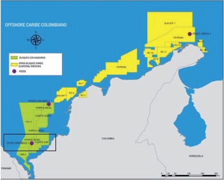
In recent years, the global trend of the development of the hydrocarbon exploitation industry has been shifting towards deep and ultra-deep waters. Situation that is not exempt to Colombia. According to recent findings, the Orca-1 Well (Tayrona Block) and Kronos-1Well (South Fort Block), in deep and ultra-deep waters respectively, (see figure 1), show the Colombian Caribbean as the newest and most promising exploratory boundary of hydrocarbons, but with great challenges (Cabrera, 2016).
Fig. 1. Blocks of interest in the Colombian Caribbean (Source: ECP)
The development of offshore activities in deep and ultra-deep waters depends on a variety of physical and environmental conditions, representing a great challenge given the technological complexity of producing hydrocarbons in these depths.
One of the main implications of these exploratory fields is that for these regions of interest the installation of fixed platforms is technically and economically unfeasible, resorting to the need for floating production systems. The naval engineering competencies are the selection of the concepts and the design of the necessary infrastructure for these developments, giving special importance to systems of semi-submersible platforms and FPSO (Floating Production Storage and Offloading), among other alternatives.
The process of selecting the type of floating ocean platform to operate in these areas of interest in the Colombian Caribbean depends directly on the initially established functional requirements. Considering especially the physical-environmental conditions present and the operational restrictions that this area supposes, the selection of systems, subsystems and the definition of a matrix of influence and quality, where the physical factors of the structure are related to facilitate the perception of how these factors influence one another, and how they are influenced.
Through preliminary studies it has been concluded that in the Colombian Caribbean, and in deep and ultra-deep waters, a semi-submersible platform system would provide all the operational characteristics to cover the present needs in the areas and fields of interest. However, a detailed analysis is necessary to select the most efficient configuration for said application.
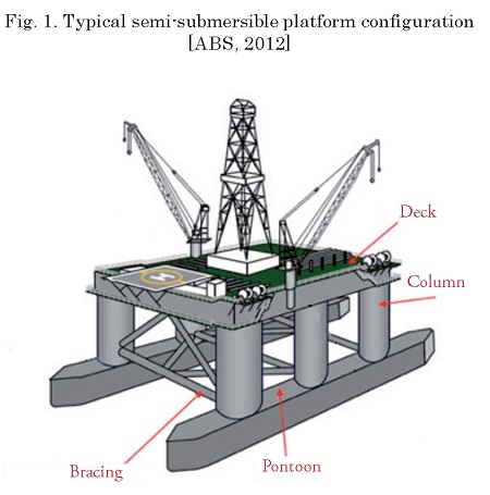
According to (Chakrabarti, 2005), semisubmersibles consist of structures with one or more decks, supported by submerged columns and floats called "pontoons". This type of structure is also called a "stabilized column", which means that the center of gravity is above the center of flotation and stability is determined by the moment of restoration of the columns. An example of the various components of the structure of a conventional semi-submersible type platform is presented in Fig. 2 (ABS, 2012).
Independent of the mission of the platform, there are two essential functions, which establish the size of the structure (Chakrabarti, 2005):
• To provide stable support for the loads on the deck under the action of the waves;
• To present minimal movements under the action of waves.
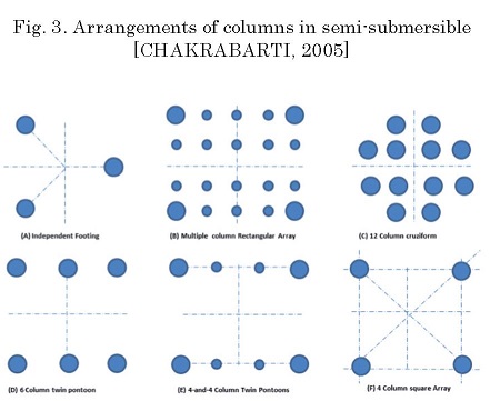
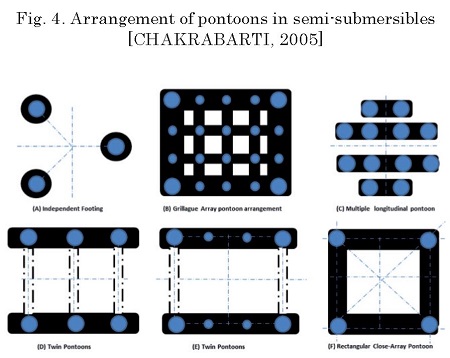
Figs. 3 and 4 illustrate a series of typical arrangements of columns and pontoons. Just as the parallel and closed pontoon arrangements are currently used, the configurations of 3 columns and closed pontoon (triangular) are used in semi-submersible applications offering a timely reduction of steel, but greater complexity in the roof.
The arrangement of closed pontoon or ring has greater resistance to the advance and therefore less push mobility, but is often preferred for a permanent fixed system, because it offers superior resistance. Follow the typical design methodologies for floating ocean systems below.
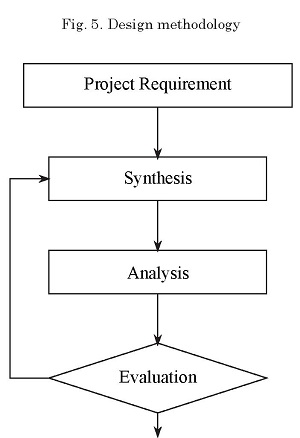
The method commonly used in the design of oceanic structures is based on concepts of synthesis, analysis and evaluation (see Fig. 5). Where the design requirements imposed by the client and the physical-environmental and operational conditions present in the area of action are defined. Based on these requirements, an initial hypothesis is proposed, to define the systems and subsystems inherent to the design process and the relationship between them. After a recommendation for solving the problem, an analysis is carried out where it is verified that the design object meets the imposed restrictions and rules (restrictive or acceptance criteria). Once the analysis process is finished, decisions are made to evaluate what was done according to the criteria established by the designers, where it is determined if the solution obtained can be improved or not, until reaching admissible values within the initial parameters of the project planned in a global evaluation.
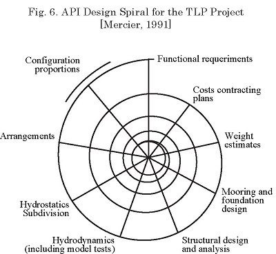
Similarly, the preliminary design of oceanic structures in many cases are based on the classical design spiral (Evans, 1959), where criteria are presented in various phases that lead to the optimization of design in terms of costs especially. Although the sequence shown in Fig. 6 is based on the experience acquired through the design of oceanic platforms, it is not considered definitive. Depending on the type of project, the criticality of each phase can be different, causing the sequence to be altered so that the most critical and critical aspects are analyzed first.
The design spiral is frequently used in the naval industry and allows an integrated and global vision of the project as a whole, highlighting the interconnections between the various phases, which has been adopted as an application model.
The experimental analysis of scale models (similar to real structures in terms of geometry and dynamics) during the design phase, in addition to allowing the reduction of costs when executing tests, in essence, allows the behavior of the original physical system to be predicted. This prediction is especially important in the operation in adverse environmental conditions, where the main natural agents (waves, wind and currents) act in a severe manner. Both (Kure, 1981) and (Chakrabarti, 1994), proposed that the design of the structure be verified by testing the model in scale in a simulated oceanic environment.
Due to the costs of the experiments and the important decisions that derive from the experimental results, it is not advisable to look for solutions to a specific problem relying only on intuition. Therefore, the design of experiments allows a sequence of tests to be structured in the form of translating the pre-established objectives by the researcher and obtaining efficiency in terms of information. Thus, the planning of the design of experiments must be carefully schematized to minimize the time and costs of the test, while maintaining reliability (Duarte, 2011).
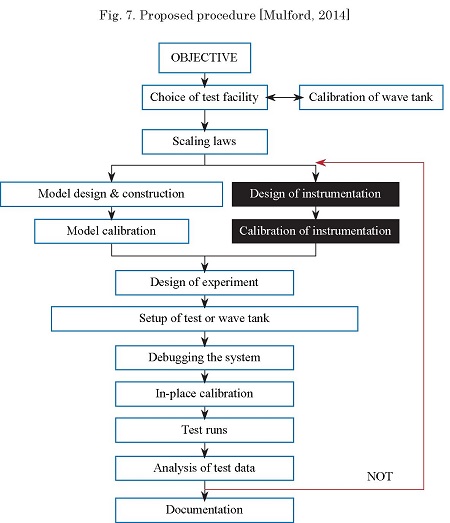
Referencing the works of (Tachibana, 1994), (Cardoza, 2002), and giving special emphasis to the research of (Chakrabarti, 1994-1998-2005) and (Steen, 2014), due to its direct connection with naval and oceanic applications in wave tanks; a methodological proposal represented in the diagram shown in Fig. 7 was established.
This proposal consists of a synthesis of recommendations, norms and rules established by authors, classification societies (DNV, ABS, BV), results of international conferences (ITTC, OTC) and research laboratories (NTNU, IPT), among others, which has been planned and coordinated efficiently and accurately to evaluate the objective problem.
The procedure consists initially of defining the type of structure (platform) and variable or physical phenomenon of interest to be evaluated.
The effective selection of the tank is based not only on the physical tank where the tests are executed. The facilities must cover different additional functions such as laboratories for building models, instrumentation, environmental simulation by computer, and also monitored data storage tools (Steen, 2014).
Regardless of the type of tank, each laboratory has a programmed calibration program. Likewise, before the execution of an assay, calibrations are carried out to guarantee the quality of the results. In the case of wave calibration, consider not using the model to ensure that calibrated waves do not contain effects associated with the model / fluid interaction (Steen, 2014).
The scale of the model is chosen as a compromise between the cost of the design and the technical requirements for similarity. In addition, the definition of the scale is directly associated with the infrastructure of the available test tank, seeking to avoid the problems of wave reflection in the walls of the tank and the blocking and repositioning of the model when carrying out the tests.
The selection of the scale factor starts from the definition of the laws of similarity, which quantify the response of the scale model in relation to the real structure. For the study of the phenomenon of fluids, there are three basic laws: Geometric, kinematic and dynamic similarity.
Scale factor
Where the relationship between the scale model (LM) and the real model (LF) is constant (Chakrabarti, 1998).
The Froude number is defined as follows:
Where l is length parameter [m]; v is velocity parameter [m/s]; and g is the acceleration of gravity [m/s2].
When it is not possible to recommend an optimal scale factor for a structure without investigating all the parameters of importance, a common scale factor used in effect of water waves in a tank is 1:50. For towing tanks a typical range of scales is between 1:10 and 1:100 (Chakrabarti, 1994).
According to (Harris, 1999) the design of the model suggests:
Some typical materials used for the construction of these models are: para ffin wax, wood, foam, reinforced fiberglass.
Commonly additional internal reinforcements are used to ensure structural rigidity and behavior similar to that of the actual structure.
Within the model, weight is placed on lead or steel as a ballast method used for load monitoring. The exterior of the model is prepared and coated with high visibility inks (Steen, 2014).
According to the same author, for dynamic tests where the model presents free movement and the forces of inertia are important, the distribution of mass must be appropriate. In practical termsthe following calibration requirements must be met:
In cases where the elasticity is not important, the built model must be "sufficiently" rigid to avoid any artificial hydro-elastic effect on the structure.
In (Malta, 2010) and (Steen, 2012) the main instruments and measuring equipment used in laboratory tests are highlighted, for the structural analysis of different types of reduced scale models are used, such as: inductive transducers, angular and linear potentiometers, accelerometers, pressure gauges, extensometers, load cells, wave sensors (elevation), optical systems (cameras) for motion monitoring, etc.
Just as important as the careful planning of the test, is the appropriation of electronic tools and instruments for post-processing or manipulation of the data obtained in the tests.
In most simple applications the transducers are manufactured to have a linear relationship between the load and the output signal. The calibration of each transducer is carried out before the execution of the tests. It is advisable to perform a calibration review after the execution of the tests to ensure that the calibration factors do not have significant changes in the assemblies and to verify that all connections are correct.
The test matrix defines the formal plan constructed sequentially to conduct the experiments. Control factors are included in this matrix together with the levels and the treatment of the experiment (Fraden, 2003).
International conferences such as the ITTC (International Towing Tank Conference) and the OTC (Offshore Technology Conference) present recommendations as experimental procedures that should be considered when carrying out the tests to guarantee the veracity of the results.
The instrumentation required to measure responses must be installed in the model. Instruments not associated with the model, as in the case of wave sensors, must be installed in the tank, calibrated and adjusted.
The environmental conditions must be calibrated in advance to guarantee the execution of the tests. The model must be positioned in the specific place for the test, in an area where the minimum reflection and distortion of the waves prevails. In addition, decay tests (free oscillation) must be carried out in the model, with or without anchoring, to determine natural frequencies.
Once the model is ballasted, instrumented, calibrated and adjusted in the position, the test matrix must be executed. The data should be stored digitally if possible. The sampling frequency must be high enough to capture the physical phenomenon analyzed.
In engineering applications the results must be presented in dimensional form. To evaluate the results and compare them with databases, it is advisable to present the answers in a dimensionless way.
The analysis procedure must be fully documented to ensure reproducibility
The ITTC (ITTC, 2014) provides recommendations for the development of uncertainties analysis and argues that most sources of error in model tests are in:
It is important to document the results of the test to highlight important observations and present conclusions. The type of documentation depends on the requirements of the requestor and the characteristics of the tests.
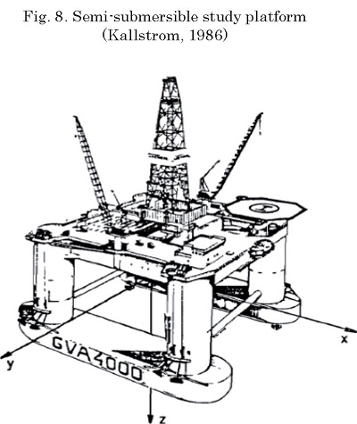
For validation purposes of the proposed methodology, the hydrodynamic study of the semisubmersible platform GVA 4000 was carried out, which is a four-column floating offshore structure in a square arrangement, with two parallel pontoons and a main deck (see Fig. 8).
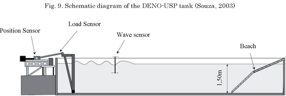
Due to availability and costs, the wave tank (DENO-USP) was used, which has the following characteristics:
This platform has a composite wave generator (with single tilting plate flap). The waves can be generated in a range of 0.5 to 3.0 Hz. (See Fig. 9).
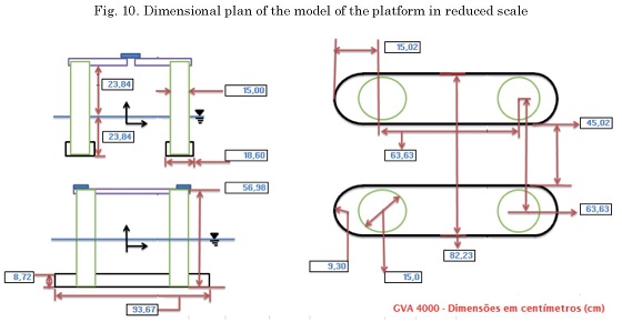
Considering the physical characteristics of the tank, a scale factor of the 1:86 model was established.
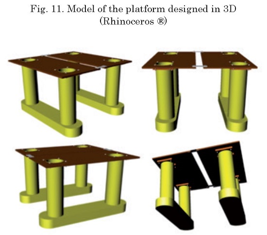
The model in dimensional plane (see Fig. 10) and in 3D was designed with the use of commercial computational tools (see Fig. 11) directly considering the main dimensions of the real structure given by the manufacturer.
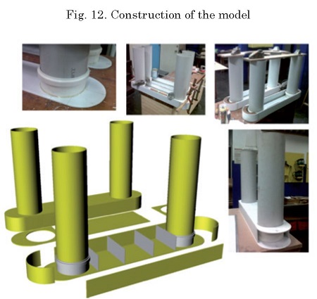
The pontoons and the columns were constructed with PVC and the deck with compensated wood. The use of epoxy resin and PVC reinforcements was crucial to give rigidity to the structure and guarantee the water tightness of the model once it is floating in the water (see Fig. 12).
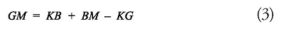
As a calibration process of the model, analytical calculations of static behavior (stability criteria) were carried out
where GM is the metacentric height, KB is the center of submerged volume (center of gravity), BM is the metacentric radius and KG is the center of gravity (see Fig. 13).
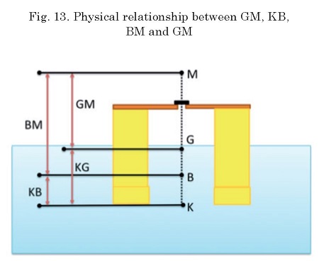
The dynamic calibration of the model began with the determination of the mass distribution, that is computationally simulated and experimentally validated, considering the center of mass in the geometrical center of the platform and the inertia of the radii of rotation (Kxx, Kyy and Kzz) given by the manufacturer of the real structure (see Fig. 14).
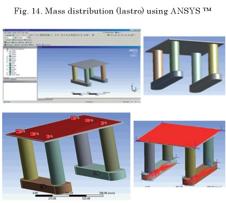
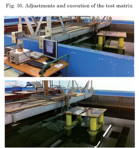
Figs. 15 and 16 shows a diagram of the assembly, positioning and calibration of the model in the wave tank and the final adjustment respectively.
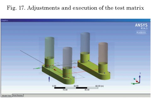
The computationally designed and simulated model for determining the natural frequency parameters of the structure and RAO response in the different degrees of free movement of the platform is represented in Fig. 17.
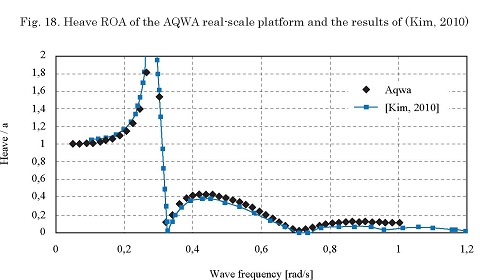
It is important to consider the peak frequency (see Fig. 18) best known as the natural frequency of the system, to avoid resonance effects by trying to keep the structure away from the oscillation frequency of the fluid medium.
The experimental response of natural frequency obtained by the model is equivalent to approximately 0.4 Hz according to the analytical calculations (2.52 Rad / s « 0.401 Hz) which represents concordance with the constructed physical model.
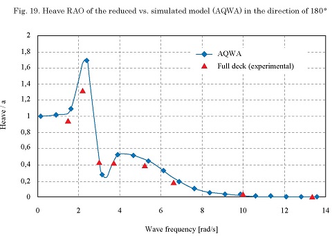
This simplified form of obtaining RAO is only possible in tests with regular waves where the excitation frequency is approximately the same as the response.
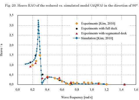
In Figs. 19 and 20 the constructed model validates the hydrodynamic behavior obtained in computational simulation, especially in relation to natural frequency.
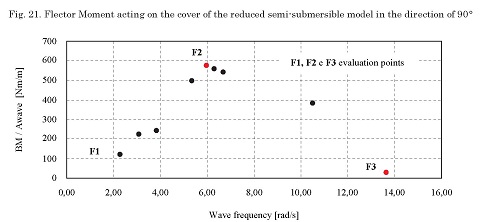
In Fig. 21 it is verified that the highest Bending Moment experimentally measured on the deck is presented for the case of wave frequencies of 5.97 rad / s (0.95 Hz). Such that compared to the estimate of critical wave condition given by the DNV (2B = 6.1 rad/s), it is possible to validate the efficiency of the experimental procedure carried out.
The experimental procedure developed was validated through comparison with experimental results presented in the literature. Additionally, the experimental results were also used in the evaluation of the quality of the results obtained through computational simulation, usually used in the initial phases of the design and analysis of offshore floating platforms.
The proposed procedure always sought, as far as possible and due to the available equipment to follow the recommendations and rules established by the literature.
In this sense a model capable of faithfully representing the hydrodynamic behavior of the real platform was successfully obtained. The geometric and dynamic similarity, especially with reference to the equilibrium criteria, was guaranteed.
API-RP 2T, Recommended Practice for Planning, Designing, and Constructing Tension Leg Platforms, American Petroleum Institute, April 1987.
CABRERA. J. - Nuevas fronteras y desafíos tecnológicos en aguas profundas y ultra-profundas en el caribe colombiano - DIMAR OFFSHORE CARIBE, Pag, 65 - 67, 2016
CARDOZA, E.V., Aplicação das técnicas de planejamento e análise de experimentos na melhora da qualidade de um processo de fabricação de produtos plásticos, 2002. Dissertação (Mestrado). Universidade de São Paulo, São Carlos. São Paulo. 2002. 121p.
CHAKRABARTI, S.K. Offshore Structure Modeling, Advanced series on Ocean Engineering — Volume 9, Chicago Bridge & Iron Technical Service Co., World Scientific, Plainfield, Illinois, USA. 1994. 470p.
CHAKRABARTI, S.K. Physical Model testing of Floating Offshore Structures. Marine technology Society, Dynamic Positioning Conference, October 13-14, 1998. 33p.
CHAKRABARTI, S.K. Handbook of Offshore Engineering — Offshore Structure Analysis, Inc. Plainfield, Illinois, USA. Elsevier Vol. 1 — Cap. 1,7,13. 2005. 1268p.
DUARTE, J. L. SCHWENGBER, C. Série Monográfica Qualidade — Projeto de experimentos - Universidade Federal do Rio Grande do Sul, Escola de Engenharia -Programa de Pós Graduação em Engenharia de Produção Porto Alegre, RS, Brasil. 2011
EVANS, J. H. Basic Design Concepts, ASNE Journal, American Society of Naval Engineers, 1959.
FRADEN, J., Handbook of Modern Sensors — Physics, Designs, and Applications — Cap 1 — Data Acquisition - Third Edition — Springer — San Diego, California USA. 2003. 608p.
HARRIS G., HARRY, S M., GAJANAM, Structural Modeling and Experimental Techniques, Second Edition, CRC Press LLC, USA. 1999. 808p.
ITTC, Recommend Procedures and Guidelines, International Towing Tank Conference, 2014.
KALLSTROM, C. G. AND BYSTROM, L. Dynamic Positioning of a Semi-Submersible: Results of Scale Model Tests and Computer Simulations - Society for Underwater Technology (Graham & Trotman. 1986) -SSPA Maritime Consulting AB, Goteborg, Sweden. 1986. 14p.
KIM, J., KIM, Y., SHIN S. Experimental study of motion & wave load response on semisubmersible — Ocean Engineering Research Department, MOERI/KORDI, Daejon, Korea. 2010. 4p
KURE, K. Model tests with ocean structures - Danish Ship Research Laboratory, Hjortekaersvej 99, DK-2800 Lyngby, Denmark. 1981. 6p.
MALTA, E.B. - Métodos e processos para a análise experimental de sistemas oceânicos de produção de petróleo e gás. 2010 — Dissertação (Mestrado) Universidade de São Paulo — São Paulo, Brasil. 2010. 218p.
MERCIER, J. A. Tension Leg Platforms - Progress and Prospects. Vol. 99; 1991; pp. 249-279
MULFORD, E. — Dissertação (Mestrado), Procedimento para determinação experimental de carregamentos externo para o projeto estrutural de uma plataforma semi-submersivel — Escola Politecnica da Universidade de Sao Paulo — Departamento de Engenharia Naval e Oceãnica, 192p, 2014.
SOUZA, C.A.G. Projeto, implantação e análise de um gerador de ondas - Departamento de Engenharia Naval e Oceânica, Escola Politécnica da Universidade de São Paulo — São Paulo — SP — Brasil. 2003. 10p.
STEEN, S. Experimental Methods in Marine Hydrodynamics — TMR7, Lecture notes — Faculty of Engineering Science and Technology - NTNU 'TRONDHEIM, Norwegian University of Science and Technology. 2014. 183p.
TACHIBANA, T. Método de avaliação do desempenho dinâmico de uma plataforma semi-submersível, concurso livre-docência EPUSP, São Paulo, Brasil. 1994.