Mehdi Chamanara1, Hassan Ghassemi2, Manouchehr Fadavie3, Mohammad Aref Ghassemi4
In the present study, the effect of the duct angle and propeller location on the hydrodynamic characteristics of the ducted propeller using Reynolds-Averaged Navier Stokes (RANS) method is reported. A Kaplan type propeller is selected with a 19A duct. The ducted propeller is analyzed by three turbulence models including the k-ε standard, k-ω SST and Reynolds stress model (RSM). The numerical results are compared with experimental data. The effects of the duct angle and the location of the propeller inside the propeller are presented and discussed.
Key words: Kaplan propeller, 19A duct, Turbulent models, Hydrodynamic analysis.
En el presente estudio se reporta el efecto del ángulo de ducto y la ubicación de la hélice sobre las características hidrodinámicas de la hélice con ducto, usando el método RANS (Reynolds-Average Navier Stokes). Una hélice de tipo Kaplan es seleccionada con un ducto tipo 19A. La hélice con ducto es analizada por tres modelos de turbulencia, incluyendo k-ε standard, k-ω SST y el modelo de esfuerzo de Reynolds (RSM - Reynolds Stress Model). Los resultados numéricos son comparados con datos experimentales. El efecto del ángulo de ducto y la ubicación de la hélice son presentados y discutidos.
Palabras claves: Hélice Kaplan, ducto 19A, modelos de turbulencia, análisis hidrodinámico.
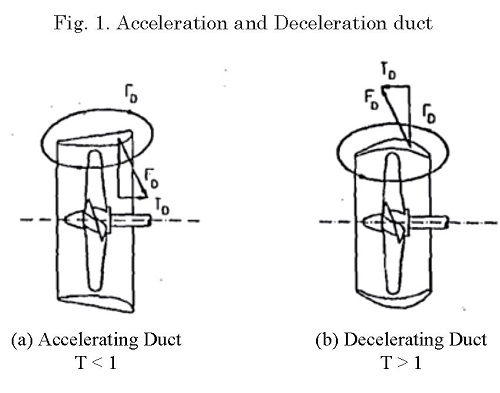
In recent year, considerable efforts have been made to improve the propulsive efficiency of the propeller on the ships. One of these propulsors is called a ducted propeller found as widespread application. The duct is generally used to obtain augment thrust, but it is also used to minimize cavitation and underwater noise or to protect the propeller from damage. There are two types of duct, the first type is called an acceleration duct or Kort nozzle and the second type is a deceleration duct. Fig. 1 shows both types of the ducted propeller. The Acceleration duct has a flat surface on the outside of the curve in the inner area. The outer surface is high-pressure surface and the inner surface is low-pressure surface (or suction). The suction allows more current to be directed into the duct and thus increase the flow rate. The increased inflow velocity causes a decrease in the thrust and torque of the propeller. At the same time, a circulation develops around the duct section resulting in an inward directed force which has a forward component, the duct thrust. The duct also has a drag directed aft. The efficiency of the ducted propeller is therefore greater than of the open propeller (Ghose, Kogarn, 2004).
In recent years, computational fluid dynamics (CFD) have been extensively used for the analysis of marine propellers. Due to the complex shape, flow turbulence, flow separation and the possibility of cavitation, the analysis of marine propellers is a difficult task; however, some works have been done in the field of ducted propellers. For example, (Taketani et al., 2009) presented the advanced design method of a ducted propeller which has high bollard pull performance. A nozzle section shape and a propeller have been designed according to a parametric study of the numerical simulation in order to have higher performance than a conventional ducted propeller. The optimum arrangement between nozzle and propeller combination is also studied. The open water tests are carried out in a towing tank of Akishima Laboratories. (Tadeusz et al., 2009) have completed the design for ducted propellers using the new computer systems. In this paper, the performance of the five different ducts are compared and the result show that in most cases only the 19A duct was considered, and that this duct was designed for low speed and high bollard pull conditions. (Celik et al., 2010, 2011) presented a design methodology for the operation of ducted propellers in a non-uniform wake field. They also presented an investigation of optimum duct geometry for a passenger ferry. The numerical effect of duct shape on the propeller performance was presented by (Caldas et al., 2010).
(Baltazar et al., 2012) predicted the thrust and torque of a ducted propeller using a panel method to improve the accuracy of the calculated shape of wake panels and the flow behavior in the tip gap region. The numerical analysis employed to the ducted propeller performance under open water test condition (Yu et al., 2013). They also investigated the open water performance of the Ka-series propellers at various pitch and expanded area ratios in combination with the 19A duct by employing the panel method PAN-MARE and the RANSE code ANSYS-CFX. (Krzysztof et al., 2014) presented four diff erent geometries ducts to get better thrust characteristics in medium and high advance velocity ratio. (Xueming et al., 2015) analyzed the hydrodynamic performance of the ducted propeller by different turbulent models. They presented the pressure distribution on the propeller surfaces, the pressure and the velocity vector distribution of the flow field around the ducted propeller. They showed that the Reynolds stress model (RSM) is better that the k-ε standard model.
The hydro-acoustic characteristics of the ship propeller in uniform and non-uniform flow were determined by (Gorji et al., 2016). (Majdfar et al., 2015 and 2017) presented the numerical results of the hydrodynamic characteristics of a ducted propeller operating in oblique flow. Hydrodynamic characteristics of the Kort-nozzle propeller by different turbulence models carried out by (Chamanara and Ghassemi, 2016).
Various studies have been done on a ducted propeller, but analyzing a ducted propeller by using different turbulence models and comparing them with each other, studying the effects of propeller position along the duct and duct angle relative to propeller on hydrodynamic characteristics have not been studied. In this paper, a Kaplan propeller with a 19A duct is used for CFD analysis. First, 19A duct data, especially data on the beginning and end of the duct which do not find in any references, are provided to model the duct geometry. Then, the ducted propeller is analyzed by using three different turbulence models including k-ε standard, k-ω SST and RSM and the results are compared with experimental data. Furthermore, the effects of the propeller position along the duct on hydrodynamic characteristics are investigated and the position in which the maximum thrust is produced will be determined. Finally, the effects of duct angle relative to propeller on hydrodynamic characteristics are studied.
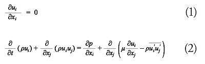
In the present study, it is assumed that the fluid is incompressible. The governing equations consist of the mass and momentum conservations. Using the Reynolds averaging approach, the Navier—Stokes equations can be stated as:
where  is the Reynolds stresses.
In many important engineering flows, we deal with rotating or swivel flows. Rotating flows occur in turbo machinery, mixing tanks, marine propellers and a variety of other systems. Equations (1) and (2) are solved in a stationary coordinate system but sometimes it is useful to be solved in a moving coordinate system. When we are looking at moving parts from the stationary coordinate system, the flow zones result in a stability problem, but with a choice of rotating reference frame around the moving parts, the stability problem is solved. For simple problems, if we do not have any stationary zone, the single rotating reference frame (SRF) method can be used. For complex geometries, using the SRF is not possible. In this case, the problem is divided into several zones and two methods of MPM and MRF can be applied. The MPM method, despite being more accurate, due to the inclusion of interactions between the stationary and moving zones, requires a high computational time. In this paper, the MRF method is used, because not only does it need low computational time but it also has acceptable accuracy levels.
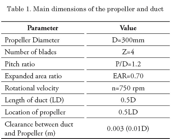
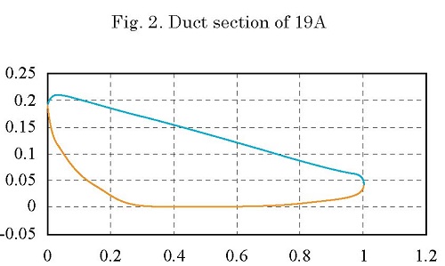
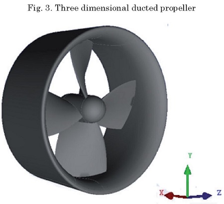
The ducts are mostly used with 19A and 37 in ships with the Kaplan propeller. So, here we employed Kaplan propeller with a 19A duct for the analysis. The main dimensions of the ducted propeller are shown in Table 1. The duct section is shown in Fig.2. The three dimensional 19A duct model with a Kaplan propeller is created using CATIA software as shown in Fig. 3
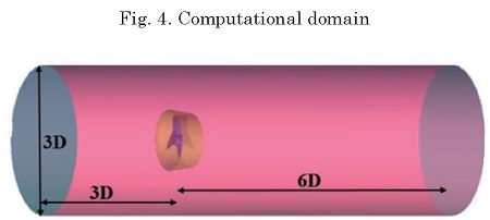
The computational domain is required to be discretized to convert the partial differential equations into a series of algebraic equations. The ICEM software is used for mesh generation. Fig. 4 shows the computational domain of the ducted propeller. The upstream part is considered to be 3D (where D is diameter of the propeller) from the mid-point of the chord of the root section. The downstream part is considered at a distance of 6D. In radial direction, the domain is considered at a distance of 1.5D from the axis of the hub.
The method of tetra/mixed type is used for mesh generation in ICEM software. The maximum size of mesh elements is 0.2 and to make better meshing in the curved parts (such as the leading edge) it is necessary to enable curvature/proximity based refinement option and to set the minimum size limit at 0.00175. The blade section is an airfoil with a sharp edge so in order to preserve the airfoil form after the mesh generation, it is necessary to set the edge criterion value in the volume meshing parameters tab to 0.08. The split wall option of a rotating zone in the partial mesh setup should be checked to create an interface between the rotating and stationary zones.
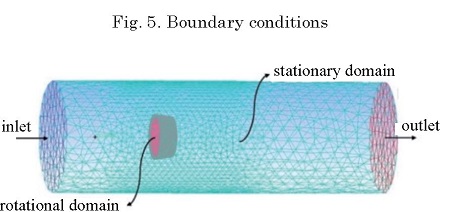
We used the MRF method which means that the computational domain is divided into two zones. The zone around the propeller is a rotational area and the other is a stationary area. The velocity inlet is changed to find the different advance coefficient. The inflow and outflow boundaries were set to velocity inlet and pressure outlet boundary conditions, respectively. The far field boundary was taken as the wall. The boundary conditions are shown in Fig. 5.
Calculations are carried out by the “Fluent software” to solve the three-dimensional viscous incompressible flow. The steady state pressure-based solver in a segregated mode was implemented using the MRF technique.
To find a proper turbulence model, the k-ε standard model, which has been used in most articles for ducted propeller analysis, is applied first. Then the results of this model are validated against the experimental results. In the next stage, the k-ω SST and RSM turbulence models are used and the results of these three models are compared. As a result of this comparison, the k-ω SST turbulence model is used as an appropriate model for investigating the effects of propeller position along the duct and also the effects of duct angle relative to propeller on hydrodynamic characteristics.
The number of mesh elements is checked to match the numerical results. In general, the mesh size should be small enough so that the results are not changed by increasing the number of elements. Finally, we observed that if the number of elements is equal to 2.5 million, the results will be independent of the mesh number.
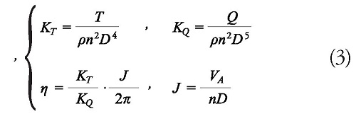
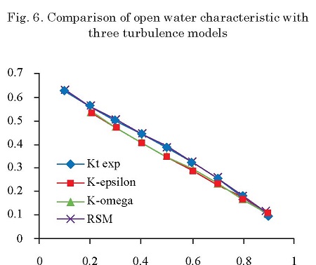
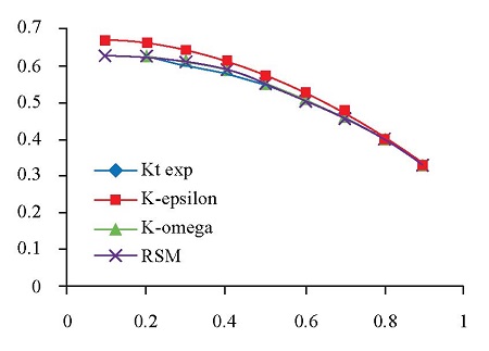
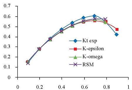
The open water characteristics of a propeller are usually given in terms of the advance coefficient (J), thrust coefficient (KT), torque coefficient (KQ) and open water efficiency Those coefficients are defined as follows:
Assuming constant rotational speed, advance velocity is changed until the advance coefficient of 0 to 1 is found and then, the hydrodynamic characteristics (KT, Kq, q ) are calculated.
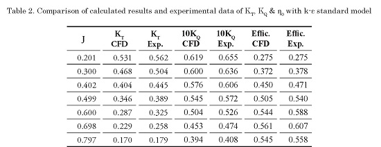
Firstly, we use the k-ε standard model for the analysis of ducted propeller. The trust coefficient, torque coefficient and efficiency are calculated and validated against the experimental. Table 2 is compared the calculated results and experimental data of Kt, KQ & η0 with the k-ε standard model.
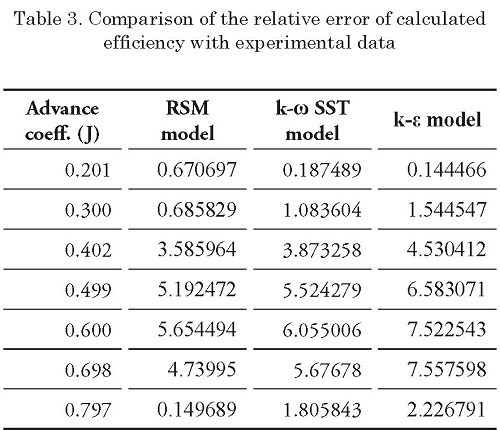
Other turbulent models like the k-ω SST, k-ε standard and RSM are also employed. Table 3 compares the relative error of calculated efficiency with experimental data for three turbulent models. As can be seen, the relative error for RSM model is smaller than the two other models. The maximum relative error is less than 6%. The k-ω SST model is better than k-e standard model. The y+ value for all models is less than 30. It should be mentioned that very fine meshes are needed near the blades to achieve the less y+.
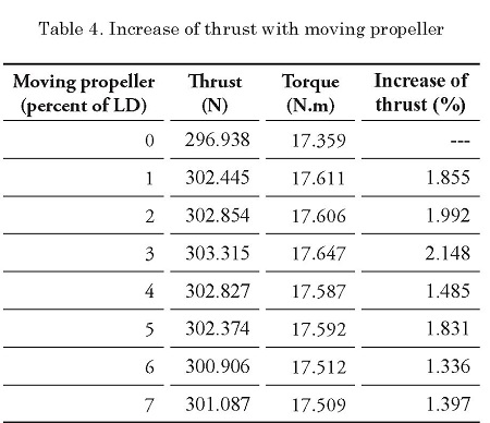
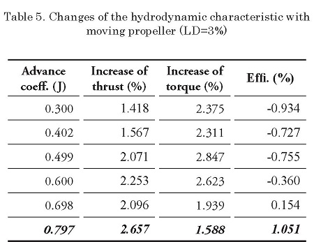
Here, the propeller is moved to the outlet direction as a percent of the duct length (LD%). The results of the thrust and torque are determined at various locations (0<LD%<7%). The thrust, torque and the percentage of the thrust is shown in Table 4. It is concluded that when LD is 3% the thrust increases about 2.148%. For other advance coefficients (when the LD% is 3), the results are given in Table 5. When the advance coefficient is 0.797 the efficiency is increased by approximately 1.05%.
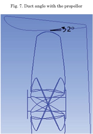
Another important point is the effect of the duct angle. The gap between the blade tip and the inner surface of the duct is 3 mm (0.001D where D is the propeller diameter) and a rotational zone is defined at this distance, so the duct or propeller cannot easily be rotated due to the duct angle. The maximum possible rotation of the duct relative to the propeller is 2 degrees counter-clockwise (CCW). Fig. 7 shows the duct angle with the propeller.
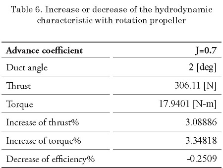
The results of the thrust and torque and their incremental are presented in Table 6. Thrust and torque are increased about 3 and 3.35% respectively. Efficiency is diminished about 0.25%.
In this study, a Kaplan propeller with 19A duct was numerically analyzed using RANS solver. Three turbulent models were studied, and the effect of propeller location and duct angles were investigated. Based on the results, the following conclusions may be drawn:
GHOSE J.P., GOKARN R.P.; "Basic Ship Propulsion”; Allied Publishers Pvt. Limited, 2004.
TAKETANI T., KIMURA K., ISHII N., MATSUURA M. and TAMURA T. “Advanced design of a ducted propeller with high bollard pull performance”, First International Symposium on Marine Propulsors smp'09, Trondheim, Norway, June 2009.
KORONOWICZ T., KRZEMIANOWSKI Z., and TUSZKOWSKA T., “A complete design of ducted propellers using the new computer system”; Polish Maritime Research, 2(60) Vol 16; pp. 34-39 10.2478/v10012-008-0019-3. 2009.
CELIK F., GUNERAND M. EKINCI S.; “An approach to the design of ducted propeller”; Transaction B: Mechanical Engineering Sharif University of Technology, Vol. 17, No. 5, pp. 406-417; October 2010.
CELIK F., DONGULAND A. ARIKAN Y.; "Investigation of optimum duct geometry for a passenger ferry”; IX HSMV Naples; May 2011.
CALDAS ALEJANDRO, MEIS MARCOS and SARASQUETE ADRIÁN; “CFD validation of different propeller ducts on open water condition”; 13th Numerical Towing Tank Symposium; Duisburg/Germany; October 2010.
BALTAZAR J., FALCÃO. DE CAMPOS and BOSSCHERS J.; “Open-water thrust and torque predictions of a ducted propeller system with a panel Method”; Hindawi Publishing Corporation International Journal of Rotating Machinery; Article ID 474785, 11 pages doi:10.1155/2012/474785,2012.
YU L., GREVE M., DRUCKENBROD M., ABDEL-MAKSOUD M.; “Numerical analysis of ducted propeller performance under open water test condition”; Springer, J Mar Sci Technol, DOI 10.1007/s00773-013-0215-4; 24 February 2013.
KRZYSZTOF SZAFRAN, OLEKSANDR SHCHERBONOS, DARIUSZ EJMOCKI; “Effects of duct shape on ducted propeller thrust performance”; transactions of the institute of aviation; no. 4 (237), pp. 84-91, Warsaw 2014.
XUEMING HE, HECAI ZHAO, XUEDONG CHEN, ZAILEI LUO, YANNAN MIAO; "Hydrodynamic performance analysis of the ducted propeller based on the combination of multi-block hybrid mesh and Reynolds stress model”; Journal of Flow Control, Measurement & Visualization, 3, 67-74; April 2015 in Sci Res.
GORJI M., GHASSEMI H., MOHAMMADI J., “Determining the hydro-acoustic characteristics of the ship propeller in uniform and non-uniform flow”, International Journal of Engineering (IJE), Transactions A: Basics Vol. 29, No. 4, (April 2016).
CHAMANARA M., GHASSEMI, H., “Hydrodynamic characteristics of the Kort-nozzle propeller by diff erent turbulence models”,American Journal of Mechanical Engineering, Vol. 4, No. 5, 2016, pp 169-172.
MAJDFAR S., GHASSEMI H., FOROUZAN H., “Hydrodynamic Effects of the length and angle of the ducted propeller”, Journal of Ocean, Mechanical and Aerospace -Science and Engineering-, Vol.25, 2015.
GHASSEMI H., MAJDFAR, S., FOROUZAN H., Calculations of the hydrodynamic characteristics of a ducted propeller operating in oblique flow, Ship Science & Technology, Vol. 10, no 20, (31-40) January 2017.
MAJDFAR S., GHASSEMI H., FOROUZAN H., ASHRAFI A., “Hydrodynamic prediction of the ducted propeller by CFD solver”, Journal of Marine Science and Technology, Vol. 25, No.3, pp. 268-275, 2017.