Luis Leal 1, Edison Flores2, David Fuentes3, Bharat Verma4
The resistance of a ship is of vital importance in giving greater viability to the development of a design project, since at lower ship resistance, the power demand to achieve a desired design speed will be lower which will reduce the amount of power to be installed in the ship resulting in lower fuel consumption. The use of computational fluid dynamics to analyze and optimize hull form and its appendages permits the hydrodynamic performance of the ship to be improved from the early design stages, allowing improvements to the hull shape and appendages. This paper shows a qualitative analysis which was performed to reduce the resistance of the OPVMKII (Second Generation Offshore Patrol Vessel) in its preliminary design stage by means of designing and integrating three types of bulbous bow with the ship's hull and analyzing the resistance curves obtained using computational fluid dynamics.
Key words: Computational Fluid Dynamics (CFD), Appendages, bulbous bow, Ship Resistance, Offshore Patrol Vessel.
La resistencia al avance de un buque, es de vital importancia para dar mayor viabilidad al desarrollo de un proyecto de diseño, puesto que a menor resistencia al avance, la demanda de potencia para alcanzar una velocidad de diseño deseada será menor y con esto disminuir la cantidad de potencia instalada en el buque, lo que se traduce en menor consumo de combustible. El uso de la dinámica de fluidos computacionales para analizar y optimizar las formas del buque y sus apéndices permite, desde tempranas etapas del diseño, mejorar el desempeño hidrodinámico del buque, permitiendo generar mejoras a las formas y apéndices del casco. El presente trabajo muestra en su etapa preliminar, el proceso de análisis cualitativo de la reducción de la resistencia al avance del proyecto OPVMKII (Patrullero Oceánico de Segunda Generación) mediante diseño e integración al casco del buque con tres tipos de bulbos de proa, y el análisis de los resultados obtenidos en las curvas de resistencia al avance usando dinámica de fluidos computacionales.
Palabras claves: Dinámica de Fluidos Computacional (CFD), Apéndices, bulbo de proa, Resistencia al avance, Buque Patrullero Oceánico.
The Corporation for Science and Technology for the Development of the Maritime and River Naval Industry, Cotecmar has built 3 oceanic patrol vessels (OPVs) that are operated by the Navy of the Republic of Colombia. To comply with new requirements in missions, capacities and growth margins, a design was started from scratch of a second generation OPV type vessel. The preliminary design phase of this vessel is currently under development.
Within the development in the design spiral, this phase of the project seeks to optimize the resistance to the advance of the vessel that as mentioned above, influences the amount of installed power, the weight of engines and fuel consumption. The CFD (Computational Fluid Dynamic) tool is of great importance for the development of analysis of this type of vessel, thanks to the advance in the processors and current computational capacities that allow more accurate simulations to be performed with greater precision. The CFD workshops in Gothenburg, 2010 (Larsson et al., 2010) and Tokyo, 2015 show that the CFD methods developed can achieve good results compared to experimental results. RANS methods are currently a common tool used in design departments to support the design process. The accuracy of the CFD analysis is proven to be accurate, and most naval architects use this method for initial design phases instead of channel testing that is tedious, expensive and time consuming.
The analysis of advance resistance is a fundamental initial step in the design of a new vessel, these analyzes are regularly made in a channel of test experiments to refine aspects of resistance reduction, the analysis of the behavior of the ship at sea, optimization of the shape lines of the hull itself, but a good approximation can also be obtained by simulating the aforementioned analyzes through calculations using the CFD tool, although the admissible results of this method is in the order of 5-10% when compared with the results of channel tests. It will always be necessary to confirm these data with a channel test, so this computational analysis provides sufficient information for a good qualitative analysis and can present approximate values.
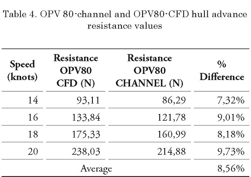
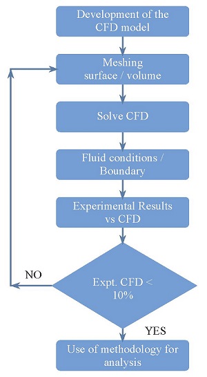
Initially, the validation of the computational model will be carried out with a channel tested model and CFD model, with which resistance to advance results will be obtained and the percentages of difference will be compared to the point of having maximums of 10% for the case of qualitative analysis as it is the object of study of this document.
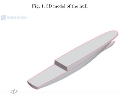
For the correct validation of the model, the hull of the OPVMKII vessel will be analyzed at a design speed of 20 knots as the maximum speed (real scale). The analysis will be carried out in calm and deep waters. 4 speeds were simulated to recreate a curve of advance resistance, this for the bare hull (without appendages). After this 3 types of bulbs will be designed and simulated under the same conditions. At the end we will obtain results of 4 models, for each model a resistance curve with 4 points will be charted and it will be defined if it is efficient to place a bow bulb and if so, which of the 3 types of designed appendages present lower results of advance resistance.
To address the steps considered for the simulation of the computational model, it is necessary to describe some items that are a fundamental part in the construction of the model as follows.
The governing equations are the RANS equations and the continuity and momentum equations for the average speed of the unstable, threedimensional and incompressible flow.
To model the fluid flow, the solver used a finite volume method that uses the integral formulation of the Navier-Stokes equations. The RANS solver uses a predictor-corrector approach to link the equations of continuity and momentum.
The turbulence model selected in this study was a standard k-ε model. The use of the turbulence model formulation of the standard k-E equation is reasonably robust and reliable near solid boundaries and recirculation regions such as ship boundary layers.
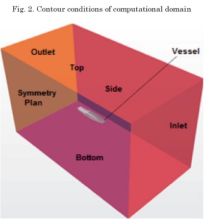
The height of the computational domain is 3.5 Lwl and its width is taken as 2 Lwl due to the symmetry of the problem. The entry limit of the domain is at a distance of 1 Lwl in front of the vessel, while the exit limit is 3 Lwl from the stern of the vessel. ITTC recommends that the entry limit should be 1- 2 Lpp and the exit limit should be 3-5 Lpp away from the hull to avoid wave reflections [2].
Inlet
The domain entry was defined as a type of contour; velocity speed (Velocity Inlet) and is the part where the flow will pass from the beginning (direction to the bow of the hull) to the end (aft direction of the hull).
Outlet
The output of the computational domain represents the place where the flow leaves it, this was defined as contour type; Pressure Outlet, represents the plane that is towards the stern of the vessel and with normal in the direction of the negative "x" axis.
Bottom, Side and Top
The bottom, side and top of the domain in this case was defined as contour type; Wall with a sliding option that works allowing the flow of water or air to pass through.
Symmetry Plane
The plane of symmetry works for the cases in which, when simplifying the problem, only half of the computational domain can be used for the symmetry of the model, if the physical phenomenon allows it. In this case the physical model obeys the interaction of the dragging pressures of the ship element and the free surface of the sea, so that having certain assumptions as the condition of the sea that for the model is of calm waters there are no reflections or sums of waves that can change the result of the calculations of the equations in this part of the domain (free surface), which is why the declaration of domain symmetry works. Then the symmetry plane condition only reflects the results of half of the analyzed or simulated domain.
Vessel-Wall
The ship in this case is represented by a wall type element (Wall) that prevents the passage of the flow through it and that has the shape of the vessel, which allows the fluid that passes outside it to be analyzed but not the ship element.
Free Surface
The free surface is the center of attention of the hydrodynamic study, since it captures the effects of the conditions already mentioned in the computational domain that was defined as a free sliding wall. This means that the velocity component parallel to the wall has a finite value (which is calculated), but the normal wall velocity and the shear stress of the wall are set to zero.
A mesh has been configured for the validation case of approximately 1.8 million cells with 6 control volumes, each with at least 2 levels of refinement, on the other hand, for the case study of the vessel OPVMKII, a mesh of approximately 2.1 million was configured with the same control volumes, except for the aft appendages, since the geometry of the model does not include them for this analysis.
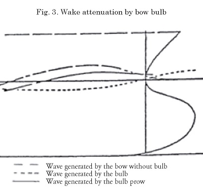
The main objective of the bow bulbs is to reduce the height of the waves caused by the local disturbance of pressures that form in the bow of the ship during its progress as indicated in Fig. 3.
The applicability of the bulb is initially defined in a Froude number range for relatively high speeds:
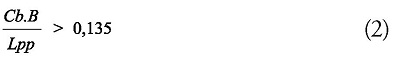
But because the Fn range is very wide, other factors that can affect the adoption of a design bulb are estimated. The global tuning parameter of the vessel indicates that the bulb is not recommended if:
Where:
Fn = Froude number
Cb = block coefficient
B = beam [m]
Lpp = length between perpendiculars [m]
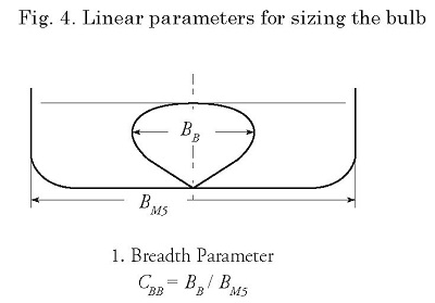
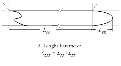
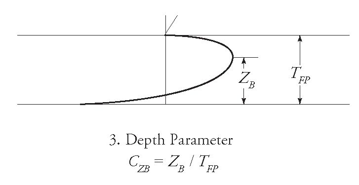
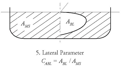
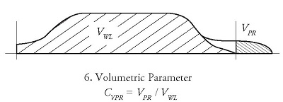
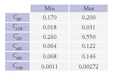
The method to identify the dimensions of the bulb once the adoption of bulb is feasible is performed by linear parameters:
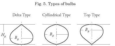
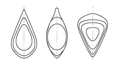
There are several types of bulbs such as those indicated in Fig. 5.
Not all the types of bulbs indicated in Fig. 5 are suitable for the OPV MKII project, since each one has a specific function, according to the hull shapes and type of service.
The research shows there are indications that the delta and cylindrical bulbs are more susceptible to suffering "slamming" due to their lower flat part and as a vessel with restricted navigation suitable for rough seas they would not be able to be used, therefore top type bulbs that maintain their fine entry angle and higher center of gravity will allow the boat to improve its performance at maximum load and make sure that the "slamming" water impacts are kept to a minimum as it is a vessel with a large number of people aboard.
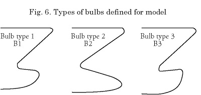
With this type of bulb selection approach, three types of variations to the bulb type B1, B2 and B3 as indicated in Fig. 5 are analyzed, where basically it is based on varying the height ZB (see Fig. 3) of bulb bulge and to verify how the dissipation of the wave train generated by the hull improves.
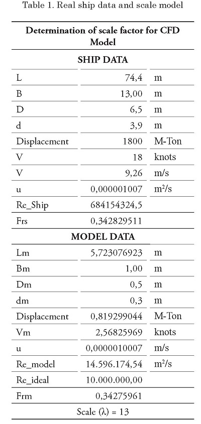
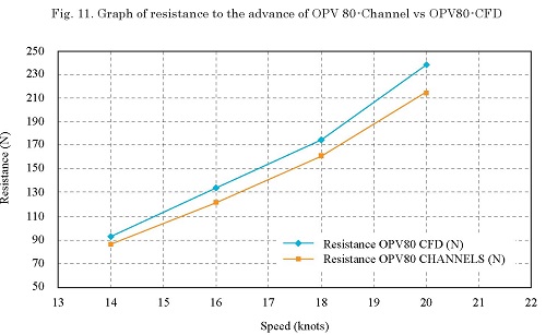
The standard vessel used for the validation of the model is the first oceanic patrol boat built in Colombia by Cotecmar OPV 80 or ARC 20 de Julio, which is currently in service, of this vessel there are accurate data of the channel tests, for hull with appendices (without propellers) and with which the comparison was made.
Ship and model data:
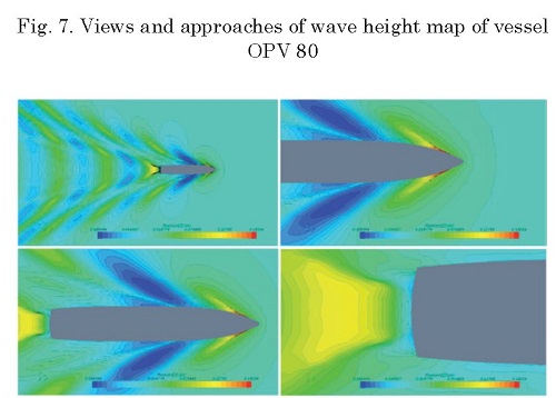
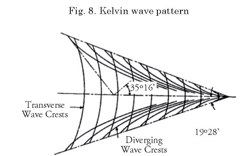
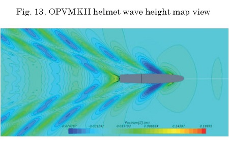
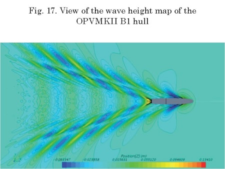
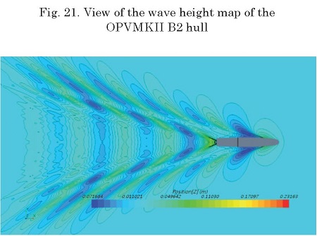
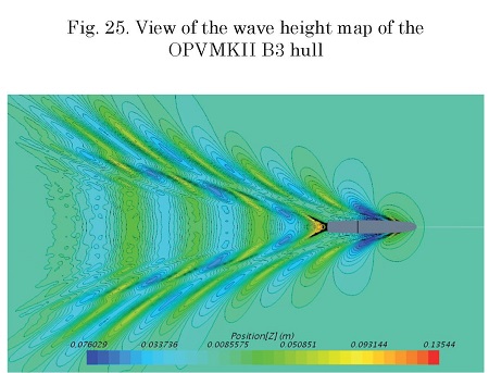
In the case of the wave map, it is necessary to compare the pattern with what is usually presented in the Kelvin wave pattern, where factors such as the angle of departure of the wave generated and the differentiation between the transversal and divergent waves are highlighted at the time of identifying computational errors of the simulation, this means that the physical phenomenon does not represent reality as it should.
As can be seen in Fig. 7 [1], the wave pattern thrown by the CFD analysis obeys the behavior shown in Fig. 8, which shows that the analysis is adequately representing the physical phenomenon.
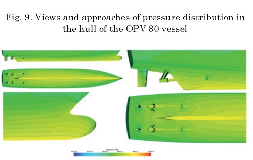
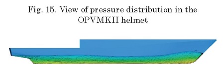
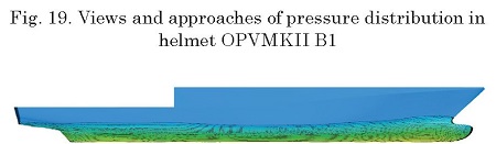
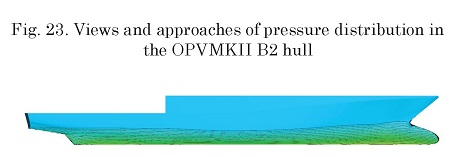
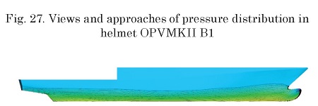
Fig. 9 shows a distribution of hydrostatic pressures in the hull of the vessel, which behave well, do not show high pressure concentration and no abrupt disturbances of the pressure lines are observed.
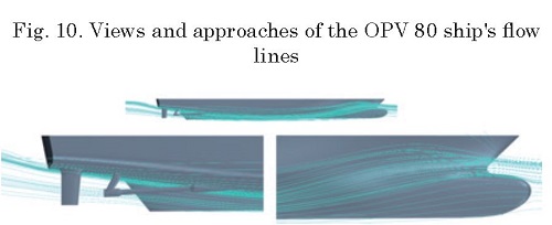
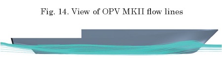
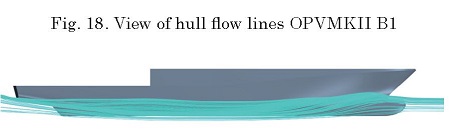
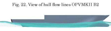
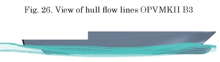
In the flow lines of Fig. 10 the most important thing is to appreciate that there is no turbulence in the middle of the flow through the hull, the height reached by the wave generated in the bow is of vital importance, because the objective of the analysis of the optimization of the resistance to the advance is to reduce as much as possible this effect to reduce the resistance to the advance of the ship.
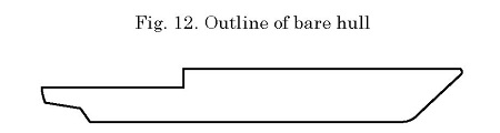
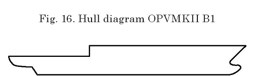
Bare hull
The bare hull is the geometry of the appendix-free model and is the starting point of the analysis, since with this first simulation it will be possible to compare whether the use of a bow bulb is efficient and functional.
Helmet with bulb type B1:
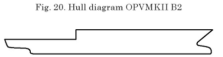
Helmet with bulb type B2:
Helmet with bulb type B3:
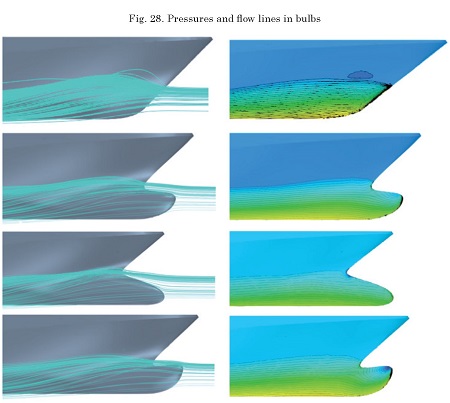
After obtaining the results of the 4 cases studied, there are no cases or models with problems of flow distortion or pressure concentration, but to appreciate a little what happens between one bulb and another, we turn to the Fig. 28
It can be see that from one bulb to another the flow lines vary, the bare hull (to the upper left) presents a wave in the bow, this is because the flow is separated by the hull and tends to form a wave that starts what we know as kelvin wave pattern, which is the cause of a greater resistance to advance, so the bulbs tested should reduce this phenomenon and effectively they do so. Bulb 1, 2 and 3 reduce the wave formed in the bow, this is because this appendage causes the flow to separate before the water touches the hull, so that it no longer opens a high resistance to the advance and with each bulb there is a defined behavior, the important thing for this case was that there was a positive effect on the flow that passes through the hull and there are no vortices or turbulence due to the shapes of the appendages or the hull.
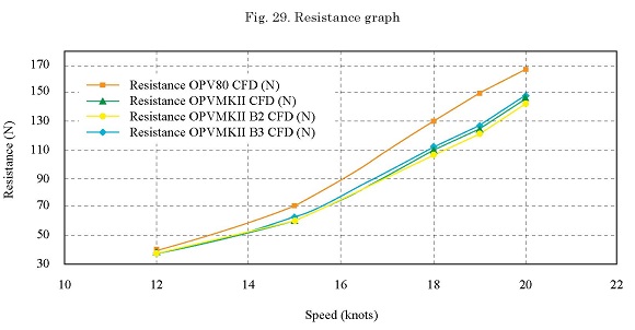
In Fig. 24 the gap between the curve of resistance to the advance of the bare hull and the 3 bulbs is notable, which denotes a clear need for the use of bow bulbs in the design of the OPVMKII hull. It can be seen that for the case of the bulbs the panorama of thedecrease in the resistance to the advance in the hull is closed, however there are considerations that can influence the use of one bulb and another, as is the case of the pitch of the vessel and the percentage of time in the life cycle that the ship will operate at certain speeds.
• Validation of the computational model was carried out, achieving a difference of less than 10% compared to the OPV80 hull channel tests, which allows us to make a qualitative analysis of the hydrodynamics of the OPVMKII hull.
• The influence of the bow bulb on the reduction of the resistance to the advance for this type of vessel was confirmed with results of around 16%.
• Comparing the 3 types of bow bulbs. The bulb that behaves best according to the graph of resistance to advance is the bulb type 2 for speeds over 18 knots, however the vessel will operate most of the time at 12 knots.
• Optimization of the hull with the inclusion of stern appendages type interceptor or wedge using CFD methodology.
• Dimensioning and selection of the anti-casting systems from the roll decay test using the CFD methodology.
• Study of behavior in the sea and maneuverability using CFD methodology.
ODD M. FALTINSEN. Hydrodynamics of HighSpeed Marine Vehicles. Norwegian University of Science and Technology. Cambridge University Press, 2005.
INTERNATIONAL TOWING TANK CONFERENCE (ITTC): Practical guidelines for ship CFD applications. Proceedings of the 26th International Towing Tank Conference, Brazil, 2011.
JEFF W. HOYLE. A Bulbous Bow Design Methodolgy for High-Speed Ships. SNAME. Vol 94, 1986.
ALFRED M. KRACHT. Design of Bulbous Bows. SNAME. Vol. 86, 1978.