Juan A. Ramírez-Macías1, Persijn Brongers2, Rafael E. Vásquez3
Designing a Remotely Operated Vehicle (ROV) is a complicated task in which the design team deals with a considerable amount of uncertainty before the device is able to be tested at full scale. A way to cope with such uncertainty is to use simulation software to evaluate design concepts along the different levels of abstraction of the process. In this work, the use of aNySIM, the Maritime Research Institute Netherlands (M AR IN) multibody time-domain simulation tool, as a part of the design process of an ROV is addressed. The simulation software is able to solve the equations of motion of the vehicle based on rigid body dynamics, including features such as hydrodynamics, hydrostatics, thrusters, thrust allocation, and PID control. Different simulation scenarios are proposed to evaluate different concept solutions to the design, including thruster parameters and distribution. The results are further used to select the concept solutions to be implemented in the final design.
Key words: Remotely Operated Vehicle Design, Time-domain simulation.
El diseño de vehículos operados remotamente (ROV) es una tarea complicada en la cual el equipo de diseño trabaja con una cantidad importante de incertidumbres antes de que el dispositivo pueda ser probado a escala real. Una forma de reducir esta incertidumbre es usar software de simulación para evaluar conceptos de diseño a lo largo de los diferentes niveles de abstracción del proceso. En este trabajo se usa aNySIM dentro del proceso de diseño del ROV; esta es una herramienta de simulación multicuerpo en el dominio del tiempo desarrollada por el Maritime Research Institute Netherlands (MARIN). El software de simulación es capaz de resolver las ecuaciones de movimiento del vehículo con base en la dinámica del cuerpo rígido, incluyendo elementos de hidrodinámica, hidrostática, propulsores, distribución de fuerza de propulsión y control PID. Se proponen diferentes escenarios para evaluar diferentes conceptos en las soluciones de diseño, tales como los parámetros y distribución de los propulsores. Estos resultados son usados luego para para seleccionar las soluciones que son implementadas en el diseño final.
Palabras claves: Diseño de Vehículos Operados Remotamente, Simulación en el dominio del tiempo.
Because of the importance of the ocean for several industries such as fisheries, transportation, tourism, and offshore industry, among others, there is an increase on the use of marine-related technologies around the world. Among such technologies, different crafts and vessels are used to perform several operations, including underwater remotely operated vehicles (ROVs) that allow people to stay safe on the surface while surveying the seabed, for instance [1].
There are works in the specialized literature regarding the design and development of underwater vehicles which state that during the early stages of the design process information is scarce [2][3][4]. As in any other marine craft design process, assessing that the designed vehicle will be able to withstand the operational conditions is of paramount importance. There are multiple interactions between subsystems, hence, the naval design process of an ROV requires several iterations and has to be done considering interdisciplinary team work [4].
The design spiral is a classical empirical approach that proposes a sequence for the design of the different subsystems. For instance, for a manned submersible [5], the sequence starts with the mission and performance requirements and then the different subsystems are approached in the following manner: component arrangement, geometry and displacement, hull and structure, propulsion plant, electrical plant, command and surveillance, auxiliary systems, outfit and furnishings, energy summary and energy storage system, weight displacement centre summary, and cost estimate summary. Once this sequence is finished, a new loop must be followed with greater level of detail. This is repeated until the design is su fficiently detailed.
Using computational tools allows the marine craft design process to be speeded up, at early stages when there is no detailed information about components and geometry or when it is not possible to perform experiments. For instance, Toxopeus et al. [6] developed tools to simulate the manoeuvrability and seakeeping of sea vehicles. Wang et al. [7] obtained the mathematical model for an underwater vehicle based on CFD calculations. Ramírez-Macías et al. [8] performed the hydrodynamic modelling of the ROV Visor3 using a viscous flow solver for the accurate prediction of manoeuvring coefficients needed for the development of control algorithms.
In this work, we address the use of aNySIM, a multibody time-domain simulation tool developed by the Maritime Research Institute Netherlands (M AR IN), as a part of the design process of an ROV when the geometry is not well known but choices must be made regarding motion-related components, focusing on the features of the ROV. The first section contains the design problem statement. Then the simulation software is described and the simulation framework is explained. After, the use of the software is exemplified using different scenarios to evaluate different concept solutions to the design of an observation class for remotely operated vehicle. Finally, some conclusions are stated.
The design problem stated here focuses on the propulsion subsystem. Here, it is assumed that there is knowledge about the ROV's overall geometry and component distribution; it is desired to make decisions on propulsion and motion-related components; and further information about other components such as the power plant is not taken into account. More specifically, the propulsion subsystem is considered as the one responsible for transforming available power into motion. Furthermore, at the stage design in question, decisions about the components involved such as thrusters and control system are to be taken.
This problem is relevant because for ROVs ocean currents impose important operational limitations. Commonly, given that the operational envelope is small, ROVs are to be operated only at calm or near to calm water conditions. If the operational envelope is to be assessed and/or optimised, during this design stage, for instance, it is convenient to perform comparison and evaluation of different propulsion system alternatives. These alternatives may include the selection of thruster's particulars such as propeller diameters, thrusters' configuration, and control strategies.
In this work, it is proposed to use time-domain simulation as a virtual prototyping tool where many features of the ROV can be modelled and nonavailable features can be implemented. The simulation results, then, can be used to make design decisions. For instance, a CAD 3D modelling tool allows the geometry and component distribution to be foreseen, to predict interferences, and calculate mass and volume properties. Here, aNySIM is proposed to be used to foresee the performance of the propulsion system and predict the operational envelope.
Different simulation scenarios to test variation of performance indices are proposed. These scenarios correspond to evaluating full thrust surge, sway, heave and yaw, forward and backward. And, for each scenario, it is proposed to test the performance of the ROV in terms of efficiency, power consumption, and operation speed. The scenarios are proposed to evaluate the following designs parameters:
aNySIM is a modular time-domain simulation program able to compute the behaviour of multiple (floating) bodies under the action of combined environmental loads such as swell, wind seas, current and wind and operation-related loads. It is used for offshore applications including coupled mooring analysis, Dynamic Positioning, multiple-body lifting operations, riser dynamics, offloading operations, etc. For instance, in [9] the positioning capabilities of a DP-controlled mono-hull deepwater drillship including a Kalman filter, PID controller and thruster interaction effects were studied. The program integrates the equation of motion for multiple bodies taking into account their own inertia, added inertia, wave loads, damping loads and hydrostatic restoring forces, as well as loads due to interactions, actuators and other mechanical components.
The simulation tool has been developed and validated over years at MARIN, and its capabilities can be extended using Lua. Lua is an extension programming language, developed at the Pontifical Catholic University of Rio de Janeiro (PUC-Rio) in Brazil that functions embedded in a host [10]. In this case aNySIM works as the host and can invoke functions to execute pieces of Lua code, as well as writing and reading Lua variables and writing and reading aNySIM's objects properties.
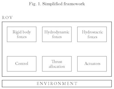
In order to develop a virtual representation of the motion problem, a framework including the building blocks, illustrated in Fig. 1, is proposed. It includes a representation of the ROV and its surrounding environment. The ROV is modelled as a rigid body, defined by its mass, moments of inertia, and centre of mass. Other components of the simulation model are: hydrodynamic forces such as displacement and restoring moments; hydrodynamic forces such as drag and added mass; control algorithms; thrust allocation strategies; and actuator forces and moments. The environment representation mainly includes current effects, but effects such as waves may be included as well.
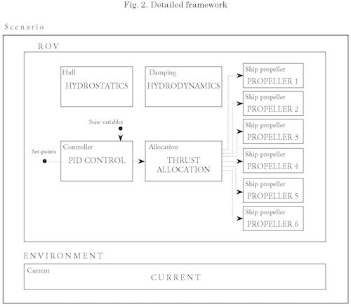
When the motion problem is implemented in aNySIM a more detailed framework may be described (see Fig. 2). Here, each model feature is represented by an object inside the aNySIM simulation scenario. The simulation scenario includes two main objects: the ROV and the environmental conditions, as well as the parameters of the numerical solver such as time step, integration algorithm, and variables to register in the file of simulation results.
The simulation framework uses an inertial Earth-fixed (EF) global system of coordinates, with an East-North-Up convention. The origin of the system coincides with the waterline. The x-direction is coincident with the initial heading of the ROV and the y-direction is directed towards portside. The z-direction is positive upwards and all rotations are right handed [11].
In aNySIM each defined body has a body-fixed frame where the x-direction, surge, is directed from stern to bow, the y-direction, sway, is directed from starboard to portside, and the z-direction, heave, is directed downwards. Roll is the rotation around the surge axis and is starboard down positive. Pitch is the rotation about the sway axis and is bow down positive. Yaw is the rotation about the heave axis and is bow to portside positive [11].
In this framework the ROV is the main body and is represented by a BodyOde rigid and defined by its mass, moments of inertia, and centre of mass. This object also wraps the objects which represent the remaining model features such as hydrostatics, hydrodynamics, actuators, and control. W hen parametrising the body, the position of the centre of mass is given in the body-fixed frame using the previously stated convention. The moments of inertia could be defined either by a full 6x6 matrix or by 6x1 vector that represents a diagonal inertia tensor.
Hydrostatic loads are defined using a hull object whose volume creates a neutrally buoyant submersible at the specified water density. Using these conditions, the object calculates non-linear hydrostatics from a water-tight 3D model (e.g. a geometry specified by a .3ds file). This captures the effects of the restoring moments produced by
the relative position of the centre of buoyancy and centre of mass.
Hydrostatic loads include drag and added mass. The added mass is directly added to the mass matrix. Drag can be defined as linear or quadratic damping objects. These objects require the definition of a matrix of coefficients which relate velocities to forces and moments, i.e.
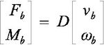
where D is a 6x6 constant matrix in the linear damping case, Fb is the body-forces vector, Mb is the body-moments vector, vb is the linear velocity vector, and cp is the angular velocities vector. In the quadratic damping case the velocity vector is replaced of an element-wise multiplication between the velocity vector and a vector of its absolute values.
The propulsion system requires the definition of two features: the thrusters' configuration and the propeller properties. This is modelled by a propeller object. Here, the configuration is parametrised by the position and orientation of the propeller. These use the X-Y-Z position and roll-pitch-yaw orientation convention previously stated. The propeller is parametrised using the diameter, diameter-pitch ratio, and number of blades.
The control system uses PID algorithms for the control of surge, sway, heave and yaw motions. Given that an ROV's motion is always pilot-assisted, the level of automation is variable among different systems. This means that at its minimum only the thrust allocation algorithm is required and more advanced algorithms are not included. In this case, yaw and heave positions and surge and sway velocities are controlled using PID controllers. It is desired to keep constant heading and depth; surge and sway control function in a fly-by-wire fashion.
For a ROV current is the most relevant environmental variable. Two options for modelling current are considered: constant current and current layer objects. The former is useful when ignoring cable effects; the latter is useful when drag accumulation along the cable is to be considered. For each case current magnitude and orientation parametrise the object. If the cable effect is to be included a dynamic line object may be defined.
In this section model particulars are considered. Parameters related to the ROV's geometry and component distribution are obtained from existing information. Parameters related to the propulsion system are assumed unknown but bounded. How these parameters are included into the model is presented in the following paragraphs.
Rigid body properties such as mass, moments of inertia and centre of mass and hydrostatics properties such as displacement and centre of buoyancy are known in this problem. The values are calculated from the available data of mass, volume and distribution of the different ROV components. It this case, a database of the different components, including their mass, volume and position in the ROV, is used to estimate the overall mass, moments of inertia, volume, centre of mass, and centre of buoyancy. These are calculated using conventional mechanics principles; details of these calculations are outside the scope of this paper.
It is assumed that the hydrodynamic loads follow Morison's equation structure, similarly as in [12]. This means that the in-line force due to hydrodynamic forces is given by
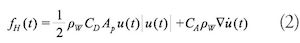
where CD is the drag coefficient, CA is the added mass coefficient, Ap is the projected area, pw is the water density, V is the volume, u is the velocity, and U is the acceleration. This means that quadratic drag is assumed. It is also considered that the added mass is frequency independent and may be added to the ROV's mass matrix. The drag coefficients are obtained from [1], assuming the drag coefficient of a cube.
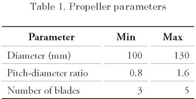
The propulsion system forces are obtained from the four-quadrant propeller theory, where ambient flow and propeller rpm determine the hydrodynamic pitch angle. This is used for table interpolation to determine non-dimensional thrust and torque coefficients. The propeller tables are dependent of the propeller's diameter, pitch-diameter ratio and number of blades. These parameters are design unknowns. The ranges shown in Table 1 are considered for these variables.
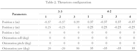
Regarding the thrusters' configuration, two different six-thruster configurations are studied: 1) three thrusters for horizontal and three for vertical movement, and 2) four thrusters for horizontal and two for vertical movement. In this study only the horizontal plane motion is considered. The position and orientation considered for horizontal motion thrusters at each configuration are shown in Table 2.
For the environmental conditions only current is considered. Here, a depth-independent generic condition where current is assumed as a constant in magnitude and orientation is used throughout all simulations. Regarding wave conditions, usually wave-effects are not considered because usually ROVs work below the wave zone. Nevertheless, if the ROV is set to work in the wave zone, these effects should be considered; this is out of the scope of this paper.
To select an adequate set of propeller parameters, full forward thrust was simulated under the assumption that only two thrusters aligned with the direction of movement were used, and the propeller speed can go up to 3000 rpm. The evaluated parameters are as follows:
All possible combinations were simulated and data at 3000 rpm are used for evaluating the parameters. Preliminary results showed that the most sensitive variable is the diameter, and the least sensitive variable one is the number of blades. Some results, as a function of diameter, are shown in Fig. 3; here, each line represents a different pitch-diameter ratio. From the plots it is apparent that higher velocities are attained for higher values of the diameter; nevertheless, higher values of power are consumed as well. If a restriction of 1 kW is enforced, an adequate value of the diameter is 120 mm.
Supposing that the diameter is 120 mm, the behaviour of the remaining variables is analysed as a function of the P/D ratio. The results are shown in Fig. 4, where different lines are plotted representing different number of blades.
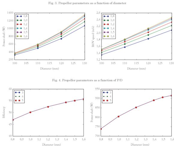
From Fig. 4 it is apparent that efficiency increases with the P/D ratio; however, the increase ratio of this efficiency decreases above 1.4. It could be theorised that it is desirable to continue increasing the P/D ratio, but, given that consumed power increases as well, a value of 1.5 is chosen. The number of blades does not modify the behaviour significantly.
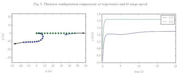
To illustrate the two proposed thruster configurations a simple scenario is proposed. Here, full forward thrust in open-loop control conditions is evaluated when a 0.6 m/s current is at 10 degree relative to the surge direction. From the results in Fig. 5 a) it can be seen that the 4-4 configuration keeps its course and the 3-3 configuration does not. There, the black arrow represents heading, the blue arrow the direction of current, and the dots different ROV positions; green dots represent the 4-2 configuration and blue dots the 3-3 configuration. It is apparent that the 3-3 configuration may work better with closed-loop control e.g. yaw control. Also, from Fig. 5 b) it can be see that, because the 4-4 configuration uses one more thruster for horizontal plane motion than the 3-3 configuration, there is a difference of 0.4 m/s in surge speed.
This paper addressed the use of a multibody timedomain simulation tool for the design process of an ROV. aNySIM was used in different scenarios to evaluate full thrust in different directions in order to test the performance of the ROV in terms of efficiency, power consumption, and operation speed. The proposed scenarios allowed the designers
to evaluate different design propeller parameters: diameter, pitch-diameter ratio, and number of blades, as well as different propeller configurations. Using simulation tools such as aNySIM allows the marine crafts designers and naval architects to speed-up the design process, when the geometry is not well known but choices must be done regarding motion-related components.
This work was developed with the funding of the Fondo Nacional de Financiamiento para la Ciencia, la Tecnología y la Innovación (National Financing Fund for Science, Technology and Innovation), Francisco José de Caldas; the Colombian petroleum company, ECOPETROL; the Universidad Pontificia Bolivariana —Medellín Campus, UPB; the Universidad Nacional de Colombia — Medellín Campus, UNALMED; through the Strategic Program for the Development of Robotic Technology for Offshore Exploration of the Colombian Seabed, project 1210-531-30550, contract 0265 - 2013.
[1] R.D. CHRIST and R.L. WERNLI, The ROV Manual, a user guide for Remotely Operated Vehicles. Oxford: Butterworth-Heinemann, 2014.
[2] S. COHAN, “Trends in ROV development”, Mar. Technol. Soc. J., vol. 42, no. 1, pp. 38-43, 2008.
[3] A.Y. MARTIN, “Unmanned maritime vehicles: Technology evolution and implications”, Mar. Technol. Soc. J., vol. 47, no. 5, pp. 72-83, 2013.
[4] J.C. CORREA, R.E. VÁSQUEZ, J.A. RAMÍREZ-MACÍAS, E.A. TABORDA, C.A. ZULUAGA, N.L. POSADA, and J.M. LONDOÑO, “An Architecture for the Conceptual Design of Underwater Exploration Vehicles”, Ingeniería y Ciencia, vol. 11, no. 21, pp. 73-97, 2015.
[5] E. ALLMENDINGER, “Chapter 1: The basic design process”, in: Submersible Vehicle Systems Design, SNAME, 1990.
[6] S.L. TOXOPEUS, C.D. SIMONSEN, E. GUILMINEAU, M. VISONNEAU, T. XING, and STERN, F. (2013). Investigation of water depth and basin wall effects on KVLCC2 in manoeuvring motion using viscous-flow calculations, Journal of Marine Science and Technology, 18(4), pp. 471-496.
[7] C. WANG, F. ZHANG, and D. SCHAEFER, “Dynamic modeling of an autonomous underwater vehicle”, J. Mar. Sci. Tech.-Japan, vol. 20, no. 2, pp. 199-212, 2014.
[8] J.A. RAMÍREZ-MACÍAS, P. BRONGERS, S. RÚA, and R.E. VÁSQUEZ, “Hydrodynamic Modelling for the Remotely Operated Vehicle Visor3 Using CFD”, IFAC-PapersOnLine, vol. 49, no. 23, pp. 187-192, 2016.
[9] J.J. SERRARIS, “Time domain analysis for DP simulations”, Proc. ASME 28th International Conference on Ocean, Offshore and Arctic Engineering OMAE2009, 2009.
[10] R. IERUSALIMSCHY, L.H. de FIGUEIREDO, and W.C. FILHO, “Lua-An Extensible Extension Language”, Journal of Software: Practice and Experience, vol. 26, pp. 635-652, 1996.
[11] MARIN, “ANYwiki: coordinate systems”, [Online]. Available: https://wiki.marin.nl/index.php/ANYwiki, [Accessed: Dec, 2016].
[12] J.P.J. AVILA, and J.C. ADAMOWSKI, “Experimental evaluation of the hydrodynamic coefficients of a ROV through Morison's equation”, Ocean Eng., vol. 38, no. 17-18, pp. 2162-2170, 2011.