Ricardo A. Lugo-Villalba1, Mario Álvarez Guerra2,Bienvenido Sarria López3
The development of ship propulsion in the areas of Economic Operation, Environmental Protection and Ship Efficiency (Triple E - Economy, Environment, Efficiency) is the comparison standard of the manufacturers of contemporary ships. The standard is based on the application of a more modern design of the diesel engines, the wide use of waste heat and the efficient operation of the ship. In accordance with the Economic Operation, the need to evaluate the design of air conditioning systems has been identified in order to determine the possible savings, which are represented by a decrease in fuel consumption, as a result of: the significant impact of this consumption in the operation of the ship, the current high costs of this energy, the periodic increase in the price of the same, and the international policies for the reduction of emissions to the atmosphere and preservation of the environment. By means of the energy diagnosis of the air conditioning system it is possible to determine the possible opportunities of energy saving during the operation of the ship. The results indicate that the thermal load and the cooling capacity required by the air conditioned spaces have a difference between their maximum and average value of 14%. This justifies the need to use a conditioning system with a variable volume of air supplied to the air conditioned space.
Key words: Thermal load, solar radiation, life cycle cost, marine air conditioning.
El desarrollo de la propulsión de los buques en los aspectos de Operación Económica, Protección del Medio Ambiente y Eficiencia de la Propulsión del buque (Triple E- Economy, Environment, Efficiency) constituye el estándar de comparación de los fabricantes de buques contemporáneos. El estándar está basado en la aplicación de un diseño más moderno de los motores (máquinas) diésel, en la utilización amplia del calor de desecho y en la operación eficiente del barco. En correspondencia con la Operación Económica se ha identificado la necesidad de evaluar el diseño de los sistemas de aire acondicionado con el objetivo de determinar los posibles ahorros, que se vean representados en disminución del consumo de combustible, dado por: el significativo impacto de este consumo en la operación del buque, los altos costos de este energético en la actualidad, el incremento periódico en el precio del mismo, y las políticas internacionales para la reducción de emisiones a la atmósfera y preservación del medio ambiente. Mediante el diagnóstico energético del sistema de aire acondicionado se puede determinar las posibles oportunidades de ahorro energético durante la operación de la embarcación. Los resultados indican que, la carga térmica y la capacidad de enfriamiento requerida por los espacios acondicionados tienen una diferencia entre su valor máximo y medio del 14 %. Esto justifica la necesidad de utilizar un sistema de acondicionamiento con volumen variable del aire suministrado al espacio acondicionado.
Palabras claves: Carga térmica, radiación solar, costo de ciclo de vida, climatización marina.
Most of the ships that are built today are based on traditional design concepts. Improvements are observed in simple components such as the engine and the propeller; but this does not apply to the ship as a complete system. Many shipbuilders concentrate and make efforts to improve capacity but, unfortunately, they still consume a lot of fuel unnecessarily.
The shipbuilding industry makes very little effort to reduce operational costs for new vessels or for repaired vessels, as the builder is not responsible for the fuel bill; in general, little time and resources are devoted to monitoring and controlling the use of energy on board ships.
Poor energy knowledge and the absence of a systematic control are the two main barriers to improving energy efficiency in ships. An important tool to overcome this barrier is the conversion of energy flow into monetary flow (money).
On the other hand, the International Maritime Organization (IMO) has established several levels of emissions to the environment. According to IMO, NOx emissions from 2016 should be below 3 g / kWh. CO2 emissions should be reduced by 30%.
Together with the requirements of the IMO for the protection of the environment, as a result of the increase in the price of crude oil, there has been an increase in the application of technologies and measures that result in fuel savings on ships
The air conditioning systems installed in the frigate units of the Colombian Navy were selected according to the initial cost, with technical capacities similar to those installed in the 1980s when these vessels were acquired, which is why it has technological equipment from 2000 but with energy consumptions similar to those originally installed.
The energy demand for air conditioning systems, for frigate type units, when in operation, on average, is above 40% of total demand. Working to increase energy savings in these systems not only improves fuel economy and economic effectiveness; it also decreases the emission of harmful substances to the environment.
This paper presents the results of applying the energy analysis to the entire air conditioning system. It shows the actual consumption and the potential energy savings that can be achieved during the daily operation of the ship.
For the calculation of the thermal load in ships, methodologies have been developed by entities such as the Society of Engineers and Naval Architects of North America (SNAME) who in the technical bulletin T & R 4-16 published the methodolog y under the name "Calculations for Merchant Ships Heating, Ventilation and A ir Conditioning Design" as well as some standards of the International Organization for Standardization (ISO) which will be taken as reference for this paper.
The methodology applied in the energy evaluation of the air conditioning system is summarized below.
The components of the thermal load are as follows:
The load components of the system are:
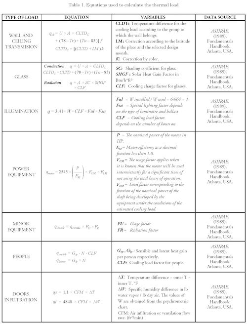
The calculation equations used are shown in Table 1.
Each frigate has an air conditioning system composed of two chiller plants of 457.2 kW (130 TR) each; one in operation and the other as
backup, this value corresponds to the hottest time of the day. The cold water is sent to six (6) handling units denominated Z which air-conditioning the residential zones and they have capacity to renew and recirculate the air. The cold water is also sent to one (1) handling unit denominated L and eight (8) handling units denominated U for workshops and warehouses; the L and U type units have recirculation capacity. The thermal load of 457.2 kW was calculated under the following conditions:
Dry Bulb Outside Temperature: 35 C Wet Bulb Outside Temperature: 27.7 C Dry Bulb Inside Temperature: 25.5 CWet Bulb Inside Temperature: 18.3 C (50% RH) Temperature of the horizontal sheet exposed to the sun: 63 CTemperature of vertical blade sheet exposed to the sun: 52 CSea Water Temperature: 29.5 C
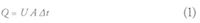
The calculation of heat transfer through bulkheads and decks exposed to the sun is performed according to the following formulation,
where U is the total heat transfer coefficient, A is the area exposed to the sun and At is the difference between the surface temperature of the sheet and the indoor temperature of the heated area.
The value of U varies depending on the external material (steel or aluminum), the structural arrangement, the thickness and type of insulation and the interior finish.
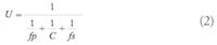
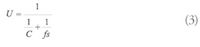
The value of the transfer coefficient U for air-air is calculated by means of the equation:
where C is the thermal conductivity of the structure material, fp is the film coefficient of the structural sheet and fp is the film coefficient of the structural reinforcements.
By means of the measurements performed in this investigation, the surface temperatures of the sheets or casings of the ship that are exposed to the solar radiation are obtained. These temperatures vary according to the position of the sun (time of day) as shown in Table 2. These values were measured in Cartagena, with the sheets painted and installed.
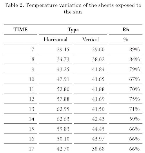
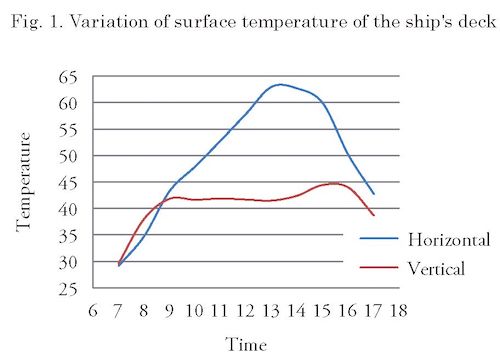
Fig. 1 shows the variation of the surface temperature of the ship's deck. Using the data in the above table, the thermal load is recalculated according to the time of day, keeping the thermal loads due to personnel, equipment, lighting, etc. constant. The results are presented in Table 3.
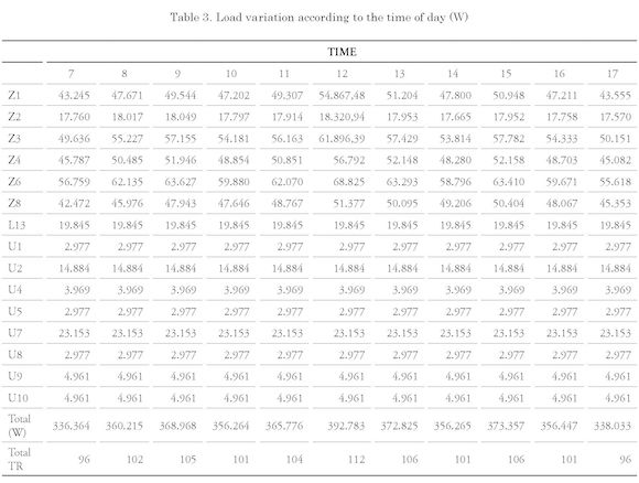
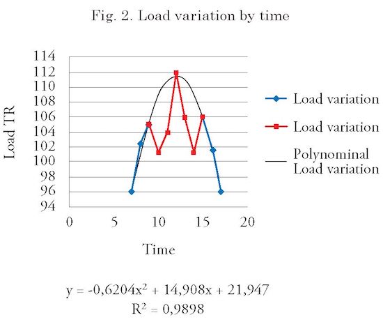
From the above table it is evidenced that at midday a maximum cooling capacity is required with 392 kW (112 TR), which is in accordance with the highest temperature of the sheet 60 C. In Fig. 2, the variation of the total thermal load is observed according to the time, in tons of refrigeration (TR).
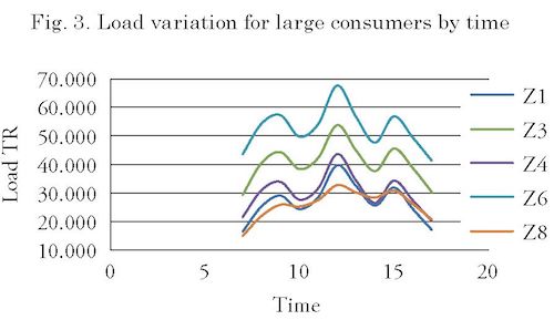
It is observed that the Zs exhibit significant variations in the thermal load, with the exception of Z2. Likewise the U and L do not present significant variations. For large consumers, the load varies according to Fig. 3
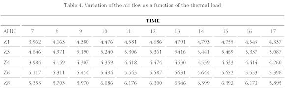
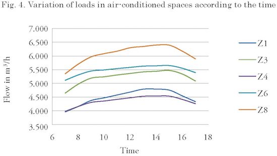
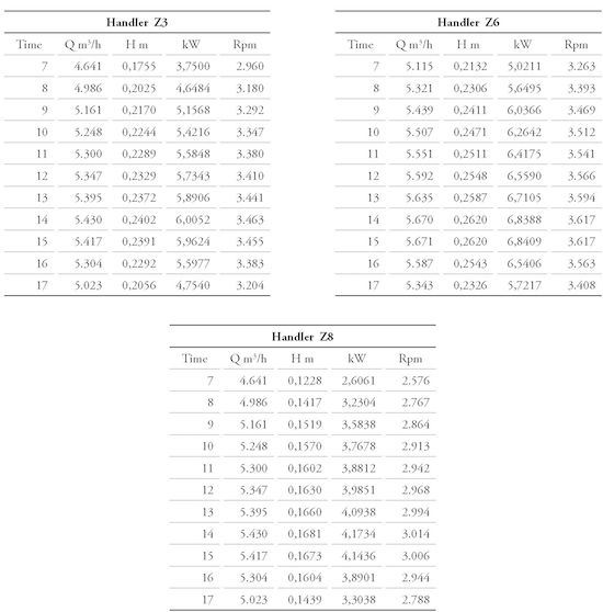
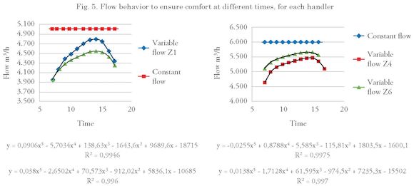
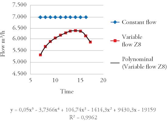
When calculating the air flow rate as a function of the variation of the thermal load, the air flow values for this condition are found, as shown in Table 4 and Fig. 4.
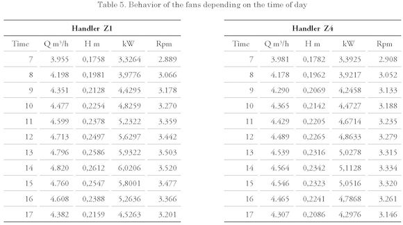
By similarity laws the velocities, powers and the results shown in Table 5 are calculated for discharge pressures of each of the fans and each handler.
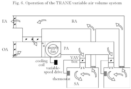
Based on the above results, a system is recommended to vary the airflow of each fan, such as a speed variator for the electric motor and to complement it with variable air flow distribution boxes which operate with sensors that open or close depending on the temperature of each conditioned room, as shown in Fig. 6. An example of the above can be seen in the catalog of the brand TR ANE VariTrane TM Products Single Duct/Dual Duct Units VAV-PRC011M-EN
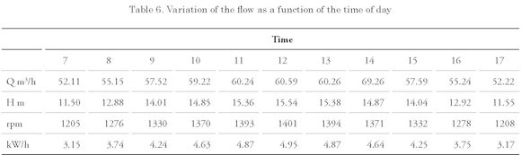
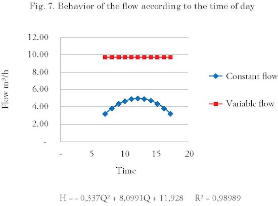
Taking into account that the thermal load varies according to the time of day, the water flow required by the Z must vary according to this load. Therefore, the calculation is performed by finding the results shown in Table 6 and comparing them with the currently installed pump as shown in Fig. 7. Therefore a system is recommended which varies the water flow of the pump, such as a speed variator for the electric motor.
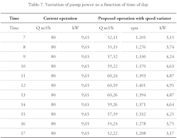
Electrical power will also vary. This variation is observed in Table 7.
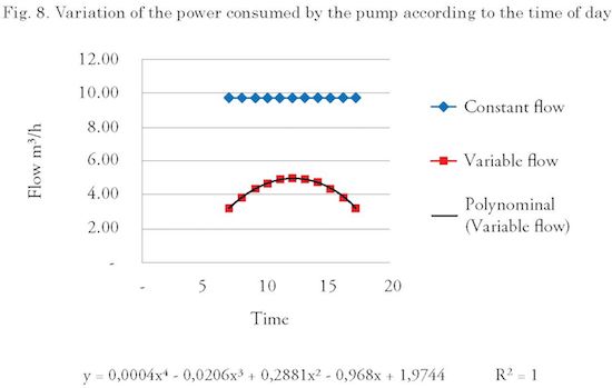
To estimate the energy savings at night, it is assumed that the pump operates the minimum flow calculated on the day, ie at 52.11 m3/h. Taking into account that the pump operates 100% of the year, current demand is estimated at 84 534 kWh year, with the speed variator, demand is estimated at 31 840 kWh year, saving 52 695 kWh year, which means savings with the proposed system are around 62.3% of current consumption. This variation is shown graphically in Fig. 8.
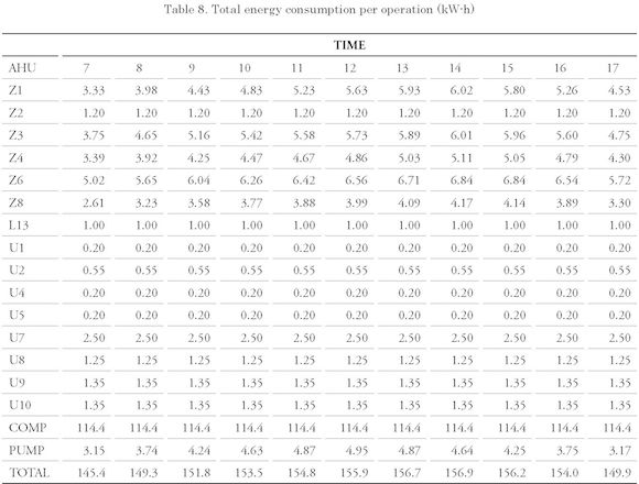
Based on the above, it is possible to estimate the total consumption per hour of the day, taking into account the consumption of the compressor, cold water pump and handlers, as shown in Table 8.
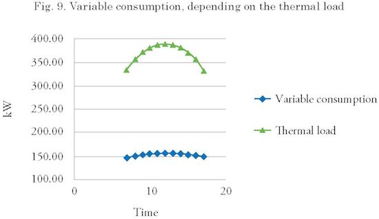
These consumptions are related to the variation of the total load due to the solar radiation on the outer sheets of the boat. For the night an average constant demand of 145 kW-h is estimated, as shown in Fig. 9.
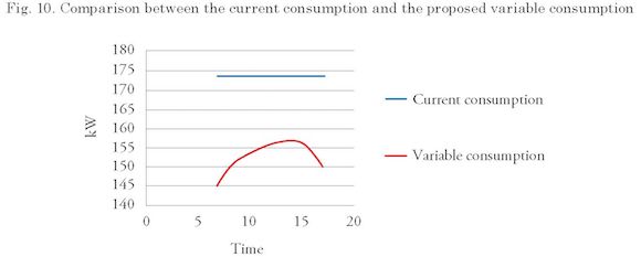
Currently the ship has a constant and independent demand of the variation of the load due to the action of the sun; the estimated value of current consumption is equal to constant 174 kW-h. Fig. 10 shows the current consumption comparison curves for the proposed variable energy consumption.
Based on the information in Table 8, consumption is estimated at 3576kWh/day for the complete system with the proposed modifications, assuming that in the hours without solar charge the demand is equal to the lowest with solar load, which means 145.4 kW-hr. Currently, the system consumes 4180 kW-h/day, which is why energy savings of 14.5% are estimated.
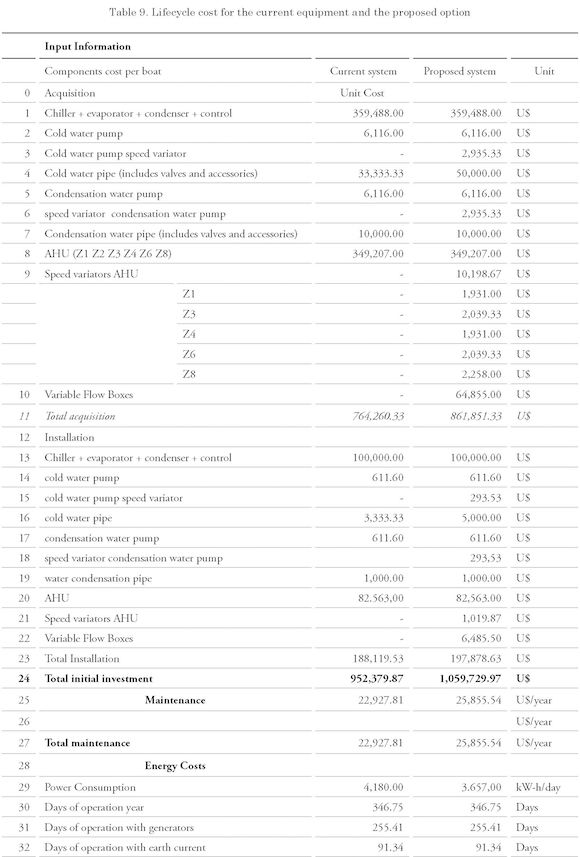
Based on the above analysis, the life cycle cost of the asset is projected from its acquisition to decommissioning taking into account installation, maintenance and operation to determine the total cost of the asset. Therefore, the life cycle cost of an asset can be calculated by the following equation:
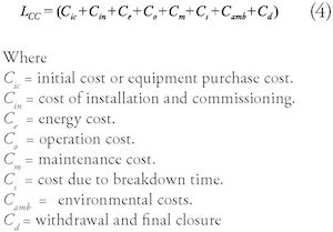
In this case, the useful life of the asset is projected in 20 years and the study is conducted in US dollars under the Net Present Value (NPV) methodology, an increase in the cost of energy and spare parts of 8% per annum, no funding is sought for the additional equipment to be installed, as shown in Table 9.
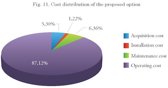
As shown in Table 9, the proposed option will save 10.17% in 20 years of operation. The distribution of costs is shown in Fig. 11.
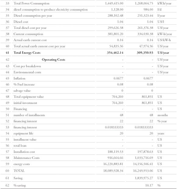
Environmental impacts are measured in accordance with the International Maritime Organization (IMO), which regulates emissions to the environment by marine diesel engines for Nitrogen Oxides (NOx) in g / kWh according to the following equation:

Where n is the engine speed equal to or greater than 130 rpm but less than 2,000 rpm. Therefore, NOx emissions generated by generators, which operate at 1800 rpm are estimated at 214 586 Ton over 20 years of equipment life for the current system and 187 377 Ton over 20 years of equipment life for the proposed system, which means avoiding the emission of 26 849 Ton NOx, (12.67%) over 20 years, with the proposed system.
The currently used thermal load calculation methods do not take into account the actual changes in temperature of the outer sheet of the vessels as a function of the time and place of operation, and therefore the result of the calculation will have constant and oversized consumption.
The operating costs of the asset correspond to 87.12% of the total costs in the life cycle, so the savings in operation will have significant impacts on the life cycle cost.
There are opportunities to save on the operation of the fans in the handling units Z and the cold water pump passing from a constant energy consumption to a variable consumption depending on the load, which varies with the time of day.
By integrating the proposed savings measures to the fans, pipes and pumps, savings of 10.17% are estimated in the life cycle of the asset.
Due to fuel savings, the environmental impacts would reduce NOx emissions by 12.6% compared to the current system.
COLOMBIA, Armada Nacional. Fragatas Clase Padilla. Manual 460 Sistema Técnico de Ventilación. 1982. [250] p.
INTERNATIONAL Organization for Standardization. ISO 7547 — Ship and marine technology - Air conditioning and ventilation of accommodation spaces - Design Conditions and basis of calculations. Geneva, Switzerland: 2002. 13 p.
ORGANIZACION Marítima Internacional. Convenio Marpol Anexo VI 73/78 - Reglas para prevenir la contaminación atmosférica, ocasionada por buques, regla 13 óxidos de nitrógeno. Londres, Inglaterra: 2002. 553 p.
OROZCO C., y CASTAÑO J. (2008). Optimización financiera de sistema de aire acondicionado para cuartos limpios. Scientia et Technica [en línea]. Año XIV, no. 39. Septiembre 2008 [Fecha de consulta: 11 de abril de 2016]. Available en: http://www.redaluc.org/articulo.oa?id=84920503034ISSN:0122-1701
RAMIREZ Carlos [et al]. Fundamentos de Matemáticas Financieras [en línea]. Cartagena de Indias, Colombia: Editorial Universidad Libre sede Cartagena, 2009 [fecha de consulta: 8 de abril de 2016. Available http://www.uv.mx/personal/cbustamante/files/2011/06/MATEMATICAS_FINANCIERAS.pdf ISBN: 978-958-8621-03-6
RODRIGUEZ Carlos [et al]. Diagnostico energético del sistema de aire acondicionado y refrigeración de un buque tipo nodriza fluvial. Ciencia y Tecnología de Buques, 1 (1): 27 — 41, Julio 2007. ISSN 1909 8642
SNAME. Technical & Research Bulletin 4-16 -Recommended Practices for Merchant Ship Heating, Ventilation and Air Conditioning Design Calculations. Jersey City, NJ, USA. 1980. 75 p.
SNAME. Technical & Research Bulletin 4-7 -Thermal Insulation Report. Jersey City, NJ, USA. 1963. 129 p.
UNIVERSIDAD de Cienfuegos. Maestría en Eficiencia Energética - Máquinas de flujo, eficiencia en su aplicación. Cienfuegos, Cuba. 2003. [100] p.