Cornelis J.J. van der Ven1, Frank Leferink2
Price development of naval ships has forced the industry to search for smarter solutions. Until recently this was not possible because the rule based approach demanded the use of maritime Eletromagnetic Compatibility Standards (EMC) that focused on equipment level. With the new Lloyd's Naval Register EMC Rules (Register, 2016), a modern risk-based approach can be followed. This enables the use of commercial Off-the-Shelf (COTS) equipment, which is more cost-effective than dedicated maritime equipment, by using the ship's structure and the installation as protection. This paper explains how these new Lloyd's Naval EMC rules can be applied for modern naval shipbuilding.
Key words: Risk based EMI approach; naval ships; Lloyd's Register; EMC management; EMC control.
La evolución de precios de los buques navales ha obligado a la industria a buscar soluciones más inteligentes. Hasta hace poco lo anterior no era posible debido a que el enfoque basado en reglas exigía el uso de Estándares Marítimos de Compatibilidad Electromagnética (EMC, por sus siglas en inglés) los cuales se centraban en la maquinaria. Con las nuevas reglas EMC de Lloyd's Naval Register (Register, 2016), es posible seguir un enfoque moderno basado en el riesgo. Esto permite el uso de equipos comerciales de venta libre (COTS, por sus siglas en inglés), lo que resulta más rentable que el equipo marítimo dedicado, utilizando la estructura del buque y la instalación como protección. Este documento explica cómo estas nuevas reglas EMC Lloyd's Naval pueden aplicarse a la construcción naval moderna.
Palabras claves: Enfoque EMI basado en el riesgo; buques navales; Lloyd's Register; Gestión de EMC; Control de EMC.
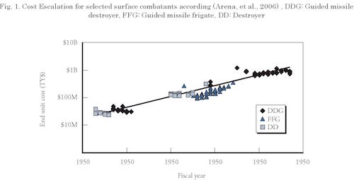
The costs for naval ships are escalating at an unsustainable rate as can be seen in Fig. 1. The data in this figure shows the price development of surface combatants of the US Navy between 1950 and 1999. If the estimated combined procurement costs of the DDG1000, DDG1001 and DDG 1002 in 2017 are added, it turns out that these ships will cost 12,738.2 M US $ (O'Rourke, 2016), which is well over 4 Billion US $ a piece. This is in line with the logarithmic price development between 1950 and 1999. Several factors contribute to this rapid increase in procurement costs of ships, but according to (Neradka, et al., 2010), 3 of them out of the top 10 of cost-drivers are EMC related standards being:
According to IEC (Electropedia, 2017) EMC stands for:
"The ability of an equipment or system to function satisfactorily in its electromagnetic environment without introducing intolerable electromagnetic disturbances to anything in that environment”
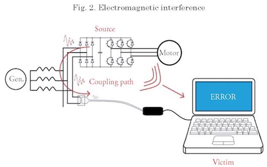
On board ships there is a range of sources generating high levels of ElectroMagnetic (EM) emission, such as radio transmitters and radar systems, for which the emissions are integral to their function. However, there are also many systems that produce EM emissions as a side effect of their functions, examples are LED-drivers and Variable Frequency Drives (VFDs). These emissions require additional mitigation measures, which increase the overall cost. If appropriate measures are not taken, the EM-emissions may cause Electromagnetic Interference (EMI) in susceptible systems such as radio receivers or sensor systems. An important aspect of EMI is the coupling path between the disturbance source and the susceptible victim, which can be through air (magnetic coupling, electric coupling or EM waves) or conductive materials (voltages and currents). Fig. 2 shows a schematic representation of how EMI may occur.
Three options are available to prevent EMI:
The traditional approach focuses on limiting EM emission levels and establishing minimum EM (ElectroMagnetic) immunity levels. The high-tech defence and space industry has developed products suitable for naval ships and meeting these emission and immunity levels. These products are robust, produce little unintentional emission and comply with military EMC standards such as MIL-STD-461-F (MIL-STD-461F, 2007) or NATO AECTP 500 series (NATO, 2016). Over time, the cutting edge electronics from this high-tech industry have also become available outside the military domain: COTS products. Because of the legal requirements posed worldwide on electronic products, like the EMC Directive in Europe (Council, 2014), the EM quality of COTS is much, much better than ever before, without any additional measures, or costs. But also, today's civil development has led to rapid mass production of reliable new technology at a much faster pace than in the defence industry. As a result of this reversal, military grade equipment today is often outdated, expensive and difficult to obtain. However, these COTS products are not designed for naval applications, and consequently could cause problems, producing higher levels of unintentional EM-emissions and may not have the immunity required by naval EMC standards. As a result, and in line with the traditional approach, today's COTS equipment is hardened to allow its use on board naval vessels. This is expensive, requires extensive testing and causes problems when equipment has to be replaced and the same type of COTS equipment is no longer available. The same applies for equipment specifically developed for the maritime market in compliance with IEC 60533 (IEC, 2015).
Until last year, if a ship was built under Lloyds Register Naval rules, only two options to comply with the EMC requirements were available (“IEC 60533” or “a naval EMC standard”), as stated in the Lloyd's Register Rulefinder (Lloyd's Register, 2015) Volume 2, Part 1, Chapter 3, Section 4.13.2.:
“An EMC test plan is to be established, an EMC analysis carried out and a test report produced in accordance with the requirements and guidelines of IEC 60533 Electrical Installations in Ships, Electromagnetic Compatibility or equivalent requirements of the Naval Administration as defined in a specified standard.”
With this requirement shipbuilders were forced to apply difficult to obtain, expensive, and often outdated equipment, because equipment which complies with IEC 60533 (IEC, 2015) is rare. The hardening of COTS equipment to have them fulfill the specific requirement at equipment level is costly, while not adding quality to the EMC performance at platform level. However with the updated Lloyd 's Register Naval Rules a third option becomes available, as can be read in Notice No.4 (Register, 2016). This option has been effected as from January 1, 2017 and includes EMC related clauses in Volume 2, Part 1, Chapter 3, Section 3.3 and section 4.13 of the Lloyd's Register Naval Rules.
Apart from following military or maritime EMC standards it is now also allowed to use a risk based ElectroMagnetic Interference1 (EMI) approach. This gives the possibility to focus less on emission and immunity levels and more on interruption of / attenuation by the coupling path. The Rules give some guidance on how this should be done and this paper will elaborate on it.
A couple of years ago several companies, knowledge institutes and the government decided to tackle the challenge of high EMC-related costs on board Naval Vessels together. This resulted in the “EMC for Future Ships” consortium which incorporated: • a navy (Royal Netherlands Navy),
Together they could optimize on ship level instead of on equipment level and substantiate this approach with thorough research which is summarized in the PhD thesis: “Requirements with rationale and quantitative rules for EMC on future ships” (Leersum, 2016). A major aspect of the thesis is the substantiation of attenuation of interference that can be obtained by proper installation methods. This was an important precondition for Lloyd's Register to allow a Risk based approach.
The risk based approach makes it harder for Lloyd's Register to validate compliance. In the past they just had to check if all equipment complied with the proper EMC standards, but now they need to make an assessment if the EMC engineering was done properly. In summary: Risk Management, instead of the Risk Avoidance when following the Rule-Based approach. To overcome this disadvantage Lloyd's Naval Rules requires at least the following documents:
The following four paragraphs will elaborate on these plans.
EMC Management plan
The EMC management plan has two important goals. The first one is to define the electromagnetic environment (EME) in which the ship will operate. In other words what does the customer want with his ship and what kind of EM threats follow from these requirements? Examples are: Impact from direct or indirect lightning strikes, Emcon2 requirements, Nuclear ElectroMagnetic Pulse3 (NEMP), Skyline4, Will the ship be sailing in convoys, Intentional ElectroMagnetic Interference (IEMI). What requirements does the customer have, for example:
The second goal is to share the responsibilities between all parties involved: the contractor, subcontractors, and suppliers. EMC can be obtained at almost any level. The component producer can make sure the components can withstand all the disturbances to which they will be exposed, for example by filtering on the printed circuit boards or proper conductive enclosures. The same applies for the equipment manufacturers. If these parties make sure their delivery complies with IEC 60533 or naval standards, a rule based approach is chosen. However, companies that integrate equipment into systems and the electrical / combat system integrators can take measures to make sure the systems run satisfactorily. For example by applying cable segregation, using power filters, using shielded cables etc. Even the yard can do a lot to reach EMC. E.g. a proper top deck design, shielded windows, and di fferent EM-zones separated with bulkheads.
If all contractors, sub-contractors, system-and equipment suppliers, and component manufacturers take all necessary steps that whatever purchased parts they use, their delivery is completely suited to be used in a Naval environment, the ship will be too expensive. If none of these parties take these steps, there is a high risk on interference resulting in malfunctions. The challenge is to make sure that the party that can prevent EMI in the naval environment against the lowest overall costs, will do so. The problem is that in practice parties often assume that one of the other parties will take the necessary steps and at the end of the day nobody did it. In the management plan responsibilities are designated to the different contracting parties to make sure one of the parties is responsible for this job. Examples of these kinds of tasks are: writing an EMC control plan, creating a top side design, performing an THD (Total Harmonic Distortion) calculation, define the earthing philosophy and so on.
Other topics to be dealt with in the EMC management plan are the legal and contractual EMC obligations. If there are standards to be adhered to, what kind of standards are they and under what conditions are they applicable. Since cooperation between all partners is important to reach EMC and a reliable ship at the lowest costs, it is important to facilitate this cooperation for example by means of an EMC team. Several procedures need to be established, for example how to deal with differences in insights between the involved companies and how to record why certain decisions were taken or solutions were chosen. Finally some thought should already be given on what kind of inspection, verification and validation is required to convince classification society and customer of the reliability of the delivered installation. Inspection, verification and validation can be real cost drivers so all involved parties should roughly know what is expected from them if they make their offer.
To summarize the management plan defines the EM-threats that follow from the requirements of the customer and states who is responsible for what.
EMC control plan
The EMC control plan is all about: controlling the identified risks, defining measures (best practices 5) to mitigate those risks, and translating them into purchase specifications for sub-contractors and system- / equipment suppliers.
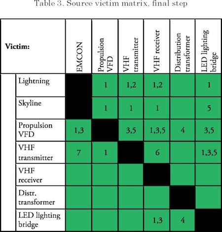
The input of the EMC control plan consists of the EM-threats and operational requirements from the customer combined with the equipment that will be used on board. An easy tool to identify the risks is a “source victim matrix”. In a source victim matrix interference risks are identified and mitigated with best practices. On the right side of the page a simplified example is given which consists of a few best practices and Table 1 up to Table 3.
If a mitigation measure is not recognized as “best practice”, proof will need to be delivered with respect to the effectiveness of the mitigation measure. However, once this is done this mitigation measure can be used in future projects.
In Table 1 the risks are identified. This is done by placing all potential disturbance sources on the left side and all possible victims on the top side. At the cross section of victim and disturbance source
Table 1. Source victim matrix, step 1
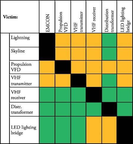
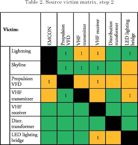
The idea is to mitigate risks so the orange cells should disappear and become green. This can be done by applying best practices, for instance a metal hull is used with EMC Multi Cable Transits (MCTs). This will prevent that currents induced by a lightning strike can reach the propulsion VFD which is placed deep within the ship. So a “1” is added to the cell at the intersection of lightning and propulsion VFD and it turns green, see Table 2. This best practice will also help to protect the VHF transmitter so a “1” is also added to that cell, but it stays orange because not all risks are mitigated. There is still an antenna sticking out of the hull which is exposed to lightning and through the antenna cable the transmitter can be exposed to high currents. However by adding surge arrestors (best practice 2) it is also possible to mitigate this risk and the cell at the intersection of lightning and VHF receiver becomes green and a “2” is added to this cell as shown in Table 3. This process can be repeated until all cells become green.
Based on the risk analysis the output of the control plan will be a number of documents and instruction which can contain, but are not limited to:
Implementation
The control plan states “what needs to be done to prevent interference”, but not in detail “how this should be done”. This subject will be dealt with in the implementation plan. An implementation plan gives, for example, information about: how to arrange cables into different groups with roughly the same disturbance levels, separation distances between those cable groups, preferred communication busses and so on. With this information installers / system manufacturers can create electrician's manuals / instructions. An electrician's manual states in detail “how the components that will be used need to be installed”. Items to be discussed: whether earth connections should be made inside or outside a cabinet, how an EMC gland needs to be mounted, where to earth cable screens and so on. It is important that requirements are specific and measurable, so it is easy to verify whether the work has been performed correctly.
The equipment manufacturer's installation instructions can conflict with the requirements from the EMC control plan. In this case a memo will be added to the implementation plan. This memo explains: how the conflict is to be dealt with, what the chosen solution is, what the consequences are and who is responsible for implementing the solution. An example is when the equipment manufacturer requires the earthing of the cable screens at only one point, whilst the EMC control plan states that they are to be earthed at multiple points.
EMC test plan
The test plan exists of two major parts a verification part, primarily performed during construction phase and a validation part, primarily performed during harbor acceptance and sea acceptance trials. The verification is all about checking if the best practices are implemented correctly and if the instructions from the electrician's manual are lived up to. This needs to be done during the construction phase because for example: “after an EMC gland is mounted, it hard to see if this was done properly”. The same applies for topics like: creating earth connections, cable separation and so on.
The validation is performed to check if the best practices are as effective as expected. Simple tests can determine this like checking the goodput of data busses, checking reception of radio signals, measuring noise levels in the VHF band, and things like that.
Time schedule
If the risk based approach is chosen it is important to do this very early in the project. The management plan needs to be created immediately after the moment the contract is signed since many aspects will be part of the contract negotiations. In an early stage of engineering the control plan needs to be created. This is necessary because the engineering department needs to know which best practices to apply and the information from the control plan is required in order to purchase systems and equipment. Then, before the detail engineering starts, the implementation plan needs to be available. Finally the verification and validation plans need to be ready before the building phase starts, since part of the verification is for example checking if the right type of frames (sta inless steel) are mounted for MCTs.
This paper explains how the new Lloyd's Register Naval Rules with respect to EMC can help to reduce EMC related costs and use state of the art technology, by applying a risk based EMI approach instead of a rule based EMI approach. A rule based EMI approach requires expensive dedicated equipment, while a risk based approach allows the use of COTS equipment if the correct ship building process is chosen. An EMC management-, control-, implementation-, verification- and validation plan combined with source victim matrices and other documents will help to implement the risk based approach properly in the ship building process.
The authors would like to thank: Lloyd 's Register of Shipping , Netherlands Defence Materiel Organisation (DMO), University of Twente (the Netherlands), Thales Nederland, Damen Shipyards (the Netherlands), and RH Marine (the Netherlands) for making resources available and provid ing back ground knowledge to perform the research that enabled the modification in the Lloyd 's Naval Rules with respect to EMC.
ARENA, MARK V., et al. 2006. A Macroscopic examination of the trends in U.S. Naval ship costs over the past several decades. Arlington : R AND Corporation, 2006.
Council, The European parliament and the. 2014. DIRECTIVE 2014/30/EU. 2014.
Electropedia. 2017. The World's Online Electrotechnical Vocabulary. [Online] 2017. [Cited: January 5, 2017.] http://www.electropedia.org/. IEC 60050.
IEC. 2015. IEC 60533: Electrical and electronic installations in ships — Electromagnetic compatibility (EMC) — Ships with a metallic hull. Geneva : IEC, 2015. IEC 60533.
LEERSUM, BART VAN. 2016. Requirements with rationale and quantitative Rules for EMC on future ships. 2016.
LLOYD'S REGISTER. 2015. Rulefinder. s.l. : Lloyd's Register, 2015. Version 9.23.
MIL-STD-461F. 2007. Requirements for the control of electromagnetic interference characteristics of subsystems and equipment. 2007.
NATO. 2016. Electromagnetic environmental effects tests and verification. s.l. : NATO standardization office, 2016. AECTP-500.
NERADKA, VINCENT F., KONEN, THOMAS R. and COLEMAN, JOSEPH W. 2010. Specification Innovation as a part of building a affordable fleet. s.l. : NAVSEA, 2010.
O'ROURKE, RONALD. 2016. Navy DDG-51 and DG-1000 Destroyer Programs: Background and issues for Congress. s.l. : Congress Research Service, 2016.
REGISTER, LLOYD'S. 2016. Notice No.4 Rules and regulations for the classification of Naval ships. s.l. : Lloyd's Register, 2016.
STANAG. 2004. 1008: (Edition 9) Characteristics of shipboard electrical power systems in warships of the north Atlantic treaty navies. 2004. STANAG 1008.