Increasing the Reliability of a Naval Tactical Data Link through the Design and Implementation of Automatic Mechanisms for Failure Recovery
Incremento en la fiabilidad de un enlace táctico naval mediante el diseño y la implementación de mecanismos de recuperación automática ante fallas
Gustavo Pérez Valdés 1, Stefany P. Marrugo Llórente 2, Eduardo Gómez Vasquez3
1 COTECMAR. Cartagena de Indias, Colombia, e-mail: gustavoperezv@gmail.com
2 COTECMAR. Cartagena de Indias, Colombia, e-mail: smarrugo@cotecmar.com
3 Tecnológica de Bolivar University. Cartagena de Indias, Colombia, e-mail: egomez@unitecnologica.edu.co
Date Received: March 20th 2016 - Fecha de recepción: Marzo 20 de 2016
Date Accepted: June 14th 2016 - Fecha de aceptación: Junio 14 de 2016
Abstract
This document describes the design and implementation process of an automatic failure recovery system on a tactical data link, with the purpose of increasing its reliability during the execution of command and control naval operations. This effort is part of a project that seeks to create a Command and Control System at an operational level. The design of the recovery mechanism begins with the state analysis of the data link system under study, it then, continues with the identification of possible “dead states” and finally, turns to the development of software solutions for each identified failure. This solution considers the communication infrastructure capabilities currently available in the Navy units, so its implementation costs are reduced. This paper also presents the results obtained from the tests carried out in the system, which show that the average failure recovery time was reduced by 50%, increasing the reliability of the analyzed data link.
Key words: Tactical Data Link, Automatic Failure Recovery, Command and Control, Communications network.
Resumen
Este documento describe el proceso de diseño e implementación de un mecanismo de recuperación automático ante fallas, en un enlace de datos tácticos, con el fin de incrementar su fiabilidad durante la ejecución de actividades de mando y control de operaciones navales. Este trabajo es parte de un proyecto que pretende crear un sistema de comando y control a nivel operacional. El diseño de los mecanismos de recuperación inicia a partir del análisis de los estados del sistema data link bajo estudio, continúa con la identificación de posibles estados muertos y finalmente, se presenta el desarrollo de las alternativas de solución por software para cada falla detectada. Esta solución contempla las capacidades de infraestructura de comunicaciones disponibles actualmente en las unidades de la Armada, por lo que sus costos de implementación son reducidos. Este documento también presenta los resultados obtenidos a partir de las pruebas efectuadas al sistema, con las cuales se evidencia que el tiempo promedio de recuperación ante una falla se redujo en un 50%, lo que incrementa la fiabilidad del data link analizado.
Palabras claves: Enlace de datos tácticos, recuperación automática de fallas, comando y control y red de comunicaciones
Introduction
Currently, when the units of some military components operate in groups/task forces, tactical information transfer among them is crucial, in order to provide a common tactical view that enables real time coordination of operations.
This information exchange must be executed through a system that ensures privacy, that is reliable, user friendly and that, because of bandwidth constraints in the available means of communication (HF - V/UHF), does not overly increase message size.
However, failures that reduce system reliability may occur during the operation. These failures may be attributed to system design issues (dead states), physical network problems (equipment failure, unit disconnection), or electronic warfare technologies used to interfere and override these types of systems.
In order to ensure the reliability of this type of system, we must thoroughly study the media access control mechanism of the tool and the system states, and identify possible failure conditions. The above, in order to be able to design automatic recovery mechanisms suitable for the analyzed system, with minimum investment in specialized hardware and applying solutions from the software component, using system synchronization as a starting point.
This work describes the methodology used to design and implement an automatic recovery system for failures detected in a tactical data link system and how this will increase the systems reliability by reducing average recovery times.
Characteristics of the system under study
The system under study is the prototype version of a Tactical Data Link developed by COTECTMAR for the Colombian Navy.
A Tactical Data Link is a tactical communication system based on radio communications that enables running the tactical information of a force or task force and improve decision making and command and control functions through information exploitation tools (COTECMAR, 2011).
Tactical Data Links (TDL) enable radio data exchange between platforms, in order to minimize voice communications that may be critical in action or combat environments (CPT/CIA, 2008). Its basic operating principle is to provide a real time link between subordinate units and their corresponding operational command. Currently, a large portion of military communications (voice and non-voice) are transmitted as data, making it easier for the military forces to coordinate their land, sea, and air-based operations (Asenstorfer, Cox, & Wilksch, 2004).
Technically, TDLs define a family of protocols known as Links, that have broadened military communication coverage through wireless networks that connect vessels, submarines, tanks, land bases, etc. These protocols lie within the physical and link layers (one and two, respectively) of the OSI reference model, defining aspects regarding Media Access Control (MAC) and information transmission on the radio links (Benavides & Montanez, 2008).
Technical characteristics of the system under study:
Functional characteristics of the system under study:
Hardware components of the system under study:
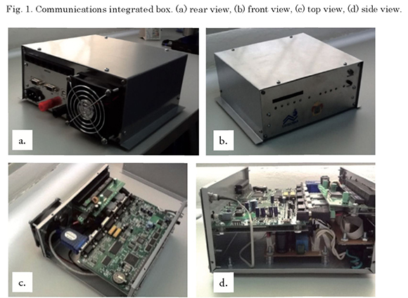
The described system is accompanied and complemented by a hardware component that ensures integration of all the system functionalities with the radio communication equipment required to carry out the information exchange in the network.
System hardware consists of a communications integrated box, which incorporates COTS1 components, such as: a multi-modem card to modulate and demodulate FSK data in the communication channels, a switch card with 8 ports to connect the on-board devices, an internal 12V and 5V DC source to power the cards and adaptors for all internal connections.
The box has an external 115VAC and 12VDC supply. It has a universal USB port for PC connection and serial ports to connect radio equipment.
Fig. 1 shows images of the communications integrated box.
Fig. 2 shows the process followed in managing the system network. Basically, the Data Link is seen as a tactical data link between the participating units in a specific operation.
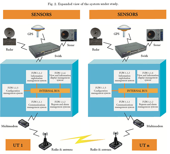
During the process of exchanging tactical information to support decision making while performing the operation, the following resources are involved:
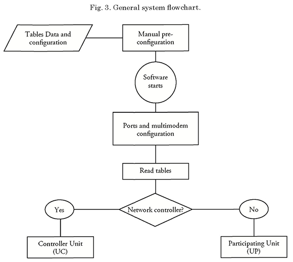
Fig. 3 shows the flowchart for the system under study for the “Normal” operation mode.
During system operations, failures may occur in some participating unit due to internal or external factors, which would cause such unit to involuntary lose connection or a significant disturbance in communications.
Below are these type of situations, for which the recovery processes of the system have been taken into consideration.
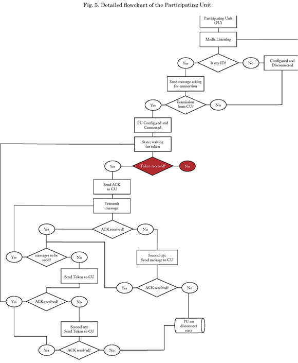
Visualization of these failures in a more detailed system scheme is shown in Figs. 4 and 5, for the CU and PU roles, respectively. Failure situations are shown in red in the schemes.
Fig. 4 shows two possible failures, seen from the CU:
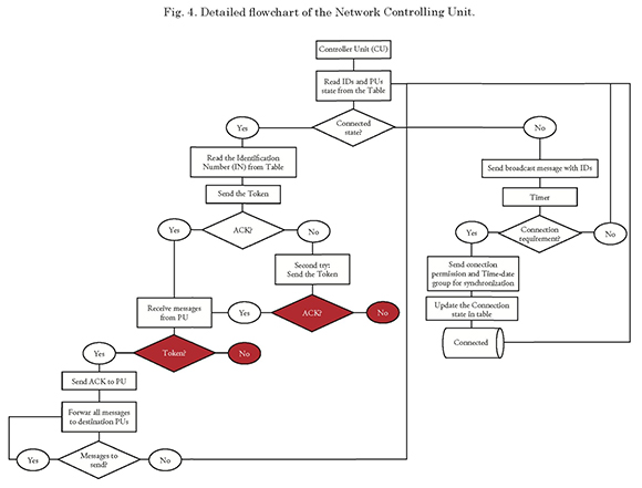
The first one (from top to bottom) is the dropout of a PU. The controlling unit sends the token to the PU and since no ACK is received, it repeats the attempt; however, the design of the system considered only the possibility of the PU reconnecting during that second opportunity, ruling out the option of voluntary or accidental disconnection of the PU; therefore, upon reaching this point, the system fails and it cannot find a state in which to operate, thus completely disconfiguring the network.
The second failure is the dropout of a PU with token. In this case, the participating unit receives the token sent by the PU, replies the ACK, and therefore the CU sent all the information available to the PU and also receives all the information coming from it, but in the end it does not receive the token. This option was not considered during the design of the system, and therefore upon reaching this point, it fails and cannot find a state in which to operate, thus completely disconfiguring the network.
Below, Fig. 12 shows the moment (seen from the PU) that generates two of the most complex failure situations:
In the current system design, it is assumed that once connected to the network, the PU will always receive the token from the CU; however, whenever the controlling unit voluntarily or involuntarily disconnects, there is no way to generate a token in the network or to manage the information exchange between the units, and therefore the system will enter into an infinite silence or the network will disconfigure since the ID of the controller unit authorizing connections will not be detected.
Now, given the naval environment in which this type of systems are used, it is possible that both the PU and the CU are connected but fail to communicate because the communication channel is blocked or disturbed (electronic warfare techniques); in this case, the PU will also assume that the CU is not connected, and therefore the point of origin of the failure is assumed to be the same one.
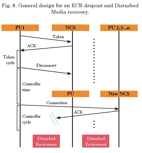
General design - failure recovery
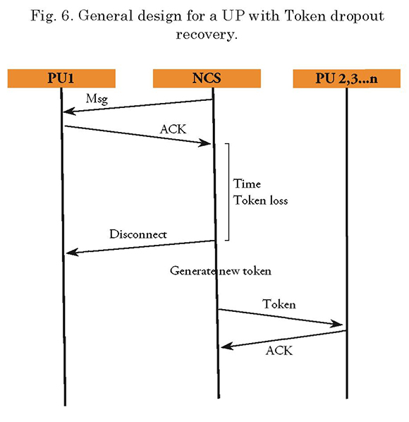
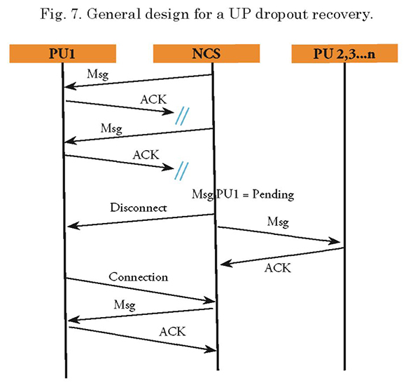
The sequence diagrams (Figs. 6-8), show an overview of the recovery mechanism to be implemented in each case.
Detailed Design - Failure Recovery
Considering the media access control of the system, and knowing that the main issue is to reduce recovery times, timers are implemented in the system as mechanisms to activate identification and fail recovery routes.
These timers will be based on the times designed for system synchronization; such times are listed and described below:
It is noteworthy that during the token cycle, wait for a Tc time so that such unit may have a time frame to connect to the network. TC is equivalent to 2To.
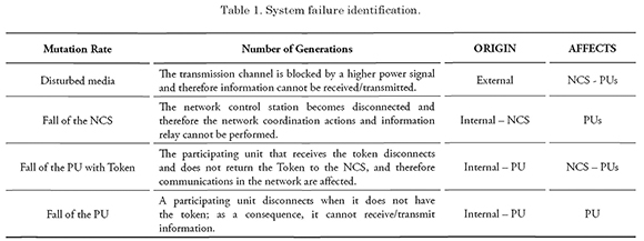
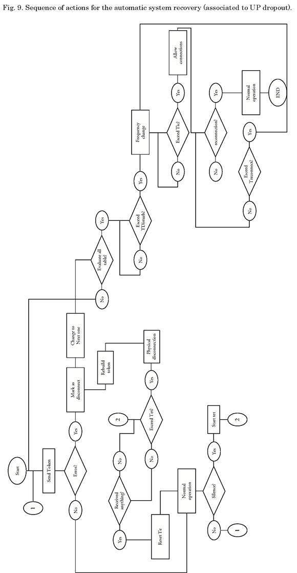
The “Disturbed media”, “fall of the PU with Token”, and “Fall of a PU” failure situations described in Table 1, will have a network recovery procedure seen from the CU or NCS as shown in Fig. 9.
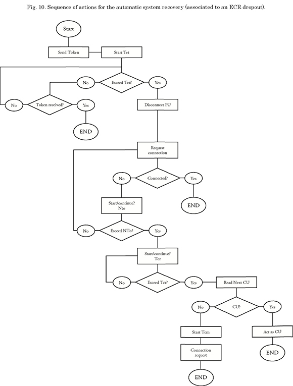
The “fall of the NCS” failure situation shown in Table 1, shall have a network recovery period seen from the PUs, as shown in Fig. 10.
Generally, the recovery mechanisms are explained as follows: in CU a timer (te) is triggered as soon as the unit receives the token ACK message, i.e. as soon as token delivery to a PU has been confirmed.
In the case of fall of the PU failure, this timer is not triggered, since the PU does not receive the token message. The proposed solution in this situation is disconnecting the unit after the second attempt to deliver the token, and to continue monitoring the connected PUs sequence to send the token. Thus, the affected PU may detect its inactivity and request a new connection in a subsequent token cycle. With this solution, the network will not lose its configuration and only the unit with problems will be affected.
For the fall of the PU with token, the CU must verify the “expiration” of the timer time (te). The purpose of this is to provide a reasonable time frame for the PU that has the token to transmit information or to reclaim the token. Once this time is exceeded, the CU will disconnect the PU and invalidate the previous token, generate a new one, and continue with the token sequence. Thus, there will be no two tokens in the network and only the failed PU is affected.
From the PU perspective, the two above mentioned procedures are not detected, unless it is the PU that had to be disconnected from the network, i.e. the failed PU. In this case, once each unit is connected and configured in the network, the timer (tet) that allows it to remain in a token-standby status is triggered. If such timeframe is exceeded, the PU shall check if it remains in a connection state; if so, it shall automatically disconnect from the network and trigger a second timer (ter). During this time frame, the PU shall remain in a “listening” mode. If it hears its ID (which is sent off by the CU) within this timeframe, it automatically sends its connection request message to the network again.
If, given the final condition set forth in the previous paragraph, the environment is still silent and the (ter) time is exceeded, the PU will automatically recognize that something happened to the CU, and it will therefore proceed to verify if it is its turn to assume CU functions. If so, the unit will auto-reconfigure and assume the CU functions. If not, a third timer (tdisturbance) will trigger. If this timer is exceeded, the PU shall interpret that it is being disturbed and will check the configured frequency table to suggest the operator switching to a secure
frequency.
Failure identification and design of recovery mechanisms
The simulation model made for the system is shown below. The entry variables for the simulation are read from an Excel spreadsheet with the entry values for the simulation. The purpose of this model is to assess how entry variable variation affects output, in order to select the values that yield the best performance, for implementation in the system.
For the simulation, a failure in the system is assumed, using a random value distribution module of values ranging between 0 and 3. Said values lead the system to a failure (according to the details in Table 1). For each type of failure, a timer is activated and the recovery actions are taken, according to the figures shown in the previous section.
Fig. 11 shows the general layout and some subprocesses of the simulation model made with the ExtendSim 8 computing tool.
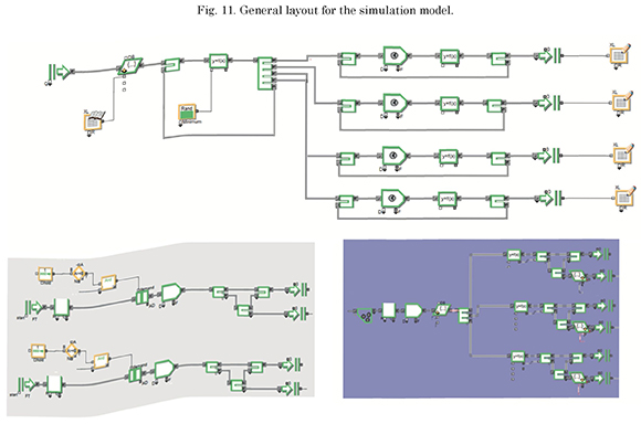
In order to simulate the recovery mechanisms, the times that the system takes to perform certain actions during experiments, such as table reading, ID identification, among others, to achieve admissible ranges in the model were taken as model input.
The simulation was ran 1000 times, and the first 100 results of the recovery time for each type of failure were taken as study data.
The simulation model was implemented for the
following input conditions:
Simulation Results
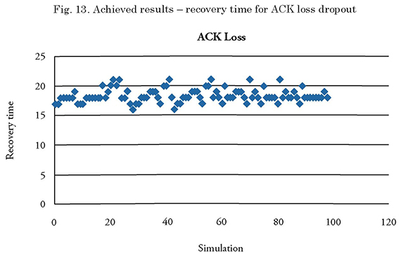
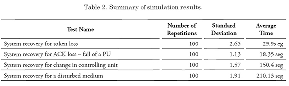
The results obtained from the simulations are shown below.
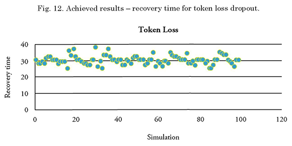
The minimum recovery time of the simulation was 25 seconds, while the maximum time was 38 seconds.
The minimum recovery time in the simulation was 145 seconds, while the maximum time was 154 seconds.
The minimum recovery time in the simulation was 16 seconds, and the maximum time was 21 seconds.
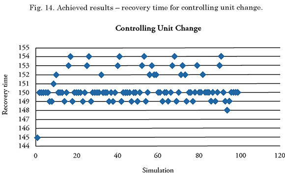
The minimum recovery time in the simulation was 145 seconds, while the maximum time was 154 seconds.
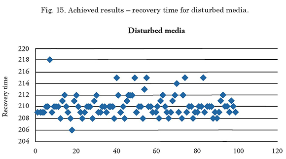
The minimum recovery time in the simulation was 206 seconds and the maximum time was 218 seconds.
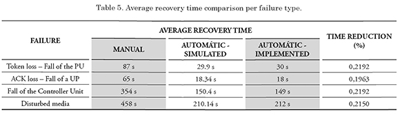
The table below summarizes the recovery times measured in the system simulation. As a result of the simulation process, we verified that the recovery times associated to each failure dropped in over 50% as compared to the times measured in manual system recovery; therefore, we confirm the feasibility of implementing the proposed mechanisms.
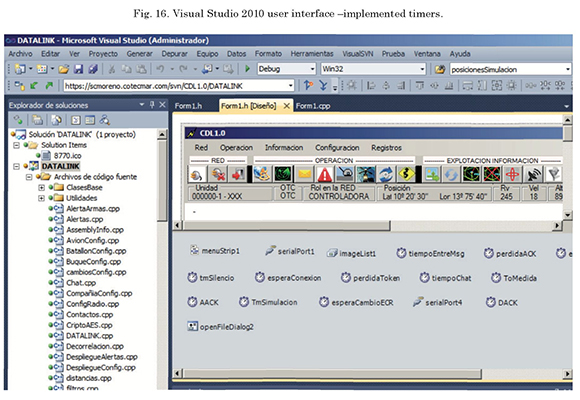
The programming language used to implement these mechanisms is C++, and the work environment was Visual Studio 2010. We used a licensed version of this tool, property of COTECMAR.
The timers implemented in the system as a comprehensive part of the proposed failure recovery model are shown in Fig. 16, which presents, in the Visual Studio 2010 graphic interface, the corresponding icons and names assigned to each one of them in the system.
Tests and implementation results
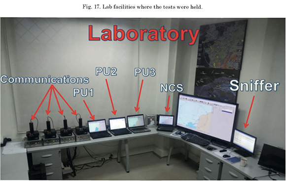
In order to verify the lab performance of the automatic fail recovery mechanism implementation, we drew a test plan consisting of four (04) packages (1 for each type of failure). The devices and/or tools considered to run the Test Plan are:
Fig. 17 shows a picture of the laboratory where tests were held. This lab is located in the COTECMAR facilities in Cartagena, and its use was authorized to runt the testing protocol of the system under study, with the implemented automatic failure recovery system.
The summary of the results obtained in the lab tests is shown in Tables 3-4. Table 3 shows the operating results, i.e. if after the failure, the network could be returned to an operating state. On the other hand. Table 4 shows the average recovery times for each one of the 50 tests ran for each type of failure.
The summary of the results obtained in the lab tests is shown below. Table 3 shows the operating results, i.e. if after the failure, the network could be returned to an operating state. On the other hand, Table 4 shows the average recovery times for each one of the 50 tests ran for each type of failure.
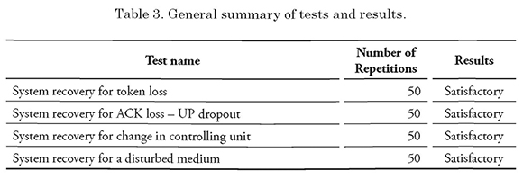

Table 5 shows the summary of the above presented results, including the reduction in the recovery time (as a percentage) between manual recovery (whose data was taken prior to the beginning of this project and the implemented automatic recovery.
System reliability
According to the specifications in Applied R&M Manual for Defense Systems Part D - Supporting
Theory, section 2.6 (page 3)2, system reliability does not have a unique measurement procedure or criteria, but it can be compared to its availability.
The authors of the article named Measuring Software Reliaibity in Practice: An Industrial Case Study3, section 2.3 “Measurement and tracking practices”, support this statement by indicating that “three (03) parameters may guide service availability/reliability measurements: failure rate (mean time to failure - MTTF), Failure coverage (for the case of hardware components — probability of detecting and correcting a hardware failure), and mean recovery time - MTTR” (Benlarbi and Storte, 2007).
Generally, in a simplified manner, the reliability of a system may be measured by the mean time between failures MTBF or MTTF, as indicated by companies such as EventFFelix4 and Vinci Consulting5, which use system availability measurements to refer to reliability.
An intuitive way to measure system reliability/ availability is by measuring the time the system is out of service.
During the initial testing stage of the Data Link system under study, the perspective of EventHelix was used to determine its reliability (when failure event recoveries were manual). In order to preserve the same measurement reference and to make valid comparisons, table 16 was also used, which has the values used by said company to measure the Data Link system reliability/availability, including the automatic failure recovery mechanisms.
The validity of the information provided by EventHelix was confirmed by comparing the data shown in Table 6 with the one provided by IBM for the same type of measurement. The availability/ reliability matrix supplied by IBM6 was extracted from their RedBook “IBM High Availability Solution for IBM FileNet P8 System .
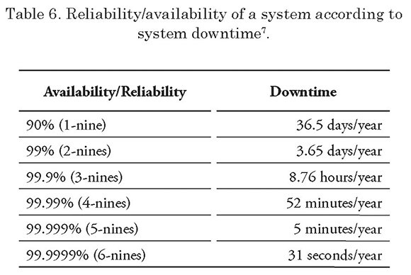
The comparison allowed for confirmation that EventHelix uses valid information to perform its measurements, since its variations do not exceed 3% as compared to the information supplied by IBM.
After validating the reference information for the specific reliability measurement experiment for the system under study, two continuous assessment periods of three (03) months (equivalent to 2160 hours) were considered.
Table 7 shows the conversion information used for periods of less than one year, equivalent to the data contained in Table 6.
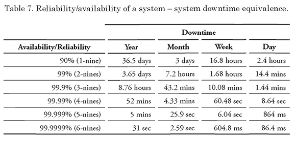
Table 8 was drawn from the information gathered during the three (03) months of testing, which summarizes the measured “downtimes”. These values correspond to the average obtained during the testing period.
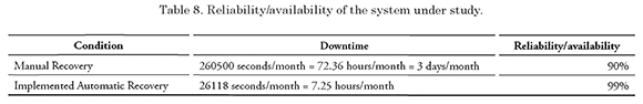
The measurements taken correspond to two conditions: manual recovery mode (data gathered between June - September, 2012) and the implemented automatic recovery mode (data collected between October 2014 — January 2015).
In general, four (04) types of failures were detected in the system under study. 50% of the failures detected were due to Token loss, whether because the NCS or the CU lost connection or because a PU left the network while holding the token. The other 50% of the failures was distributed as follows: 25% due to PU disconnections and 25% due to external factors (electronic warfare techniques).
75% of the failures detected in the system are a result of dead states in the system, while the remaining 25% are due to external factors. In the naval operating environment, direct energy radiation is the most commonly used electronic warfare technique (external factor - from the operating environment).
With the implementation of the automatic failure recovery system, the following can be affirmed:
1 Commercial Off-The-Shelf. Non-developing element (NDI) for supply, which is also commercial!.
2 Online document, available at: http://www.sars.org.uk/oldsite-archive/BOK/Applied%20RM%20Manual%20for%20Defence%20Systems%20(GR-77)/p4c06.pdf
3 Taken from the IEEE database. Drafted by officials of the Alcatel-Lucent - IP Division.
4 Online article, available at: http://www.eventhelix.com/realtimemantra/faulthandling/system_reliability_availability.htm#.VOiMnPmG9e8
5 Online article, available at: http://vinciconsulting.com/blog/-/ blogs/%E2%80%9Cthe-table-of-nines%E2%80%9D-and-highavailability
availability
6 IBM. Eligh Availability Solution for IBM FileNet P8 System. Online book, available at: http://www.redbooks.ibm.com/redbooks/pdfs/sg247700.pdf
7 Fuente: EventHelix. http://www.eventhelix.com/realtimemantra/faulthandling/reliability_availability_basics.htm#.VOiORPmG9e8
References
ALMEIDA, J.P.A.; M. Wegdam; M. van Sinderen; and L. Nieuwenhuis. Transparent dynamic reconfiguration for corba. In: Proceedings of the 3rd International Symposium on Distributed Objects and Applications, pages 197—207. IEEE Computer Society, 2001.
ARSHAD, N. A planning-based Approach to Failure Recovery in Distributed Systems. [Online]. Available at: http://www.doc.ic.ac. ukAalw/edu/theses/arshad-phd-0506.pdf. Páginas 32 -65. 2006.
ASENSTORFER, J.; T. COX and D. WILKSCH (2004). Tactical Data Link Systems and the Australian Defense Force (ADF), Technology Developments and Interoperability Issues. Edinburgh: DSTO Information Sciences Laboratory.
BERGHOFF, J.; Oswald Drobnik, Anselm Lingnau, and Christian Monch. Agent-based configuration management of distributed applications. In: Proceedings of Third
International Conference on Configurable Distributed Systems, 1996, pages 52-59- IEEE Computer Society, 1996.
BROWN, A. and Patterson, D. To err is human, 2001.
CHEN, X. and Martin Simons. A component framework for dynamic reconfiguration of distributed systems. In: Proceedings of the IFIP/ACM Working Conference on Component Deployment, pages 82-96. Springer-Verlag, 2002.
FEILER, P. and Jun Li. Consistency in dynamic reconfiguration. In: Proceedings of the Fourth International Conference on Configurable Distributed Systems, pages 189-196, 1998.
JOINT-STAFF (2001). Tactical Data Link Standarization Implementation Plan. Washington.
KAISER, G.; Phil Gross; Gaurav Kc; Janak Parekh; and Giuseppe Valetto. An approach to autonomizing legacy systems, in workshop on self-healing, adaptive and self-managed systems. In: Workshop on Self-Healing, Adaptive and Self-MANaged Systems, June 2002.
KEPHART J. y David M. Chess. The vision of autonomic computing. Computer, 36(l):4l— 50, 2003.
NORTHROP-GRUMMAN (2002). NATO Improved Link 11 NILE [online], available at http://www.ms.northropgrumman.com/ solutions/data_link_processing/data_link_ processing.html, recovered on May 2009.
PARK, J. and Pratheep Chandramohan. Static vs. dynamic recovery models for survivable distributed systems. In HICSS, 2004.
SOULES, C.; J. Appavoo; K. Hui; D. Silva; G. Ganger; O. Krieger; M. Stumm; R. Wisniewski; M. Auslander; M. Ostrowski; B. Rosenburg; y J. Xenidis. System support for online reconfiguration, 2003.
TICHY, M.; Giese, H.; Schilling, D. and Pauls, W. Computing optimal self-repair actions: damage minimization versus repair time. In WADS ’05: Proceedings of the 2005 workshop on Architecting dependable systems, pages 7-6, New York, NY, USA, 2005.
TORRES, W. Software fault tolerance: A tutorial. Technical report, 2000.
VALETTO, G.; Gail E. Kaiser; and Gaurav S. Kc. A mobile agent approach to process-based dynamic adaptation of complex software systems. In: Proceedings of the 8th European Workshop on Software Process Technology, pages 102–116. Springer- Verlag, 2001.