Evaluation of Medium Speed Diesel generator sets and energy storage technologies as alternatives for reducing fuel consumption and exhaust emissions in electric propulsion systems for PSVs
Evaluación de generadores diesel de media rotación y tecnologías de almacenamiento como alternativas para reducir consumo de combustible y la emisión de gases en sistemas de propulsión PSVs
Cristian A. Morales Vásquez1
Abstract
The use of electric propulsion systems in PSVs in Brazil has recently increased, leading to be the standard for most support vessels. In those ships, the common arrangement uses high-speed Diesel generator sets for power generation and induction motors driving propellers, reporting significant reductions in the fuel consumption and exhaust emissions compared with mechanically propelled PSVs. However, further abatements in these parameters could be achieved by implementing other technologies for power production. In this work, the use of mediumspeed Diesel generator sets and energy storage technologies in electrically propelled PSVs is evaluated. For the above, the fuel consumption, exhaust emissions, mass, volume and acquisition costs of four arrangements are estimated and compared. Two of the arrangements are equipped with medium-speed Diesel generator sets, two with energy storage units and one with high-speed Diesel generator sets. Energy storage appears as interesting alternative for decreasing fuel consumption and emissions by optimal loading of Diesel engines. Medium speed generators also showed reductions in fuel consumption, but highest emissions. The arrangements with high-speed generators presented the lowest mass, volume and acquisition costs.
Key words: Electric Propulsion Systems, Energy Storage Technologies, Platform Supply Vessels, Diesel Generator Sets.
Resumen
El uso de sistemas de propulsión eléctricos en PSVs en Brasil se ha incrementado recientemente, tendiendo a ser la norma en la mayoría de los barcos de apoyo. En dichas embarcaciones, el arreglo más común utiliza generadores Diesel de alta rotación para generación de energía y motores de inducción accionando propulsores. Tal arreglo ha reportado reducciones significativas en el consumo de combustible y en las emisiones contaminantes, comparado con los PSVs con propulsión mecánica. Sin embargo, disminuciones adicionales en estos parámetros se podrían lograr implementando otras tecnologías para la producción de potencia. El uso de generadores Diesel de media rotación y de tecnologías de almacenamiento de energía en PSVs con propulsión eléctrica, es evaluado en este trabajo. Para lo anterior, el consumo de combustible, las emisiones contaminantes, la masa, el volumen y los costos de adquisición de cuatro arreglos son estimados y comparados. Dos de los arreglos están equipados con grupos generadores Diesel de media rotación, dos con unidades de almacenamiento de energía y uno con grupos generadores Diesel de alta rotación. Las unidades de almacenamiento de energía se presentan como una alternativa interesante para disminuir el consumo de combustible y las emisiones por medio de la carga optima de los motores Diesel. Los generadores Diesel de media rotación también mostraron decrementos en el consumo de combustible pero presentan las más altas emisiones de contaminantes. Los arreglos con generadores Diesel de alta rotación presentan la menor masa, volumen y costos de adquisición.
Palabras claves: Sistemas de Propulsión Eléctrica, Tecnologías para Almacenamiento de Energía, Barcos de Apoyo a Plataformas, Grupos Generadores Diesel.
Date Received: October 10th 2014 - Fecha de recepción: Octubre 10 de 2014
Date Accepted: December 10th 2014 - Fecha de aceptación: Diciembre 10 de 2014
________________________
1 COTECMAR - Design and Engineering Management Office. University of São Paulo - Department of Naval Architecture and Ocean Engineering.
............................................................................................................................................................
Introduction
In the marine industry, Diesel Electric propulsion systems are increasingly implemented, mainly, due to the fast development of power electronics, enhancement of processing capacity of microprocessors, improved effi ciency and power density of the electrical machines. When compared with mechanically propelled arrangements, the system off ers several advantages, which, from certain points of view, compensate the higher investment costs and transmission losses at the short or medium term. Th e lower fuel consumption due to the possibility to optimize the loading of diesel generator sets; the higher reliability due to generator set redundancy; and the fl exibility in location of thruster devices, switchboards and generator sets.
Major users of electric propulsion systems are vessels in which the power demand from auxiliary/ hotel loads is as great as for the propulsion system (i.e. cruisers, passenger vessels) or vessels with changing operational conditions and equipped with electrical actuators (i.e. PSVs).
In Brazil, the number of electrically propelled PSVs is growing, leading to be the standard for most support vessels. Most of these vessels uses high speed Diesel generator sets for power production and induction motor driving propellers. Th e decrease in fuel consumption, compared with mechanically propelled PSVs, is about 700 Ton of Diesel fuel per year (Adnanes, 2003). Furthermore, exhaust emissions (CO2, NOx and SOx) are also diminished.
However, further reductions in the above parameters could be achieved by implementing other technologies for power production and energy storage. Medium speed Diesel generator sets and energy storage devices appear as appropriate alternatives for this purpose, as evaluated by Dedes, Turnock and Hudson (2010, 2012). Since medium speed Diesel engines present lower SFOC (Specifi c Fuel Oil Consumption) than the high speed ones, the operative costs are inferior. Energy storage could improve fuel consumption and exhaust emissions by maintaining the Diesel engines loaded at their optimum operational point (the loading in which the SFOC is the lowest).
In this work, the infl uence of arrangements with medium speed Diesel generator sets and energy storage devices in electrically propelled PSVs is evaluated, focusing in the fuel consumption and exhaust emissions, as well as the mass, the volume and acquisition costs. Th is purpose is achieved by a performance assessment of four electric propulsion arrangements applied to the basic hull form of a PSV: the fi rst with high speed Diesel generator sets, the second with medium speed Diesel generator sets, whereas the third and the fourth are the same as the fi rst and the second, respectively, with energy storage devices connected to the main switchboard.
Diesel-electric propulsion system for PSVs
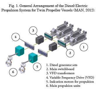
The general arrangement of the Diesel-electric propulsion system for twin propeller vessels is depicted in Fig. 1.
The prime movers drive the electric generator producing electrical energy. Th e electric power is distributed and transmitted to the propulsion motors which provide torque to the propulsion units. Th e electric motors are driven by Variable Frequency Drives (VFD) which are feed by transformers.
Energy storage devices could be added to the confi guration for load compensation, for energy back up or for supplying energy to the loads when the power demand is low. Among diff erent battery technologies, the ZEBRA batteries are reported as suitable for shipboard applications (Dedes, Turnock and Hudson 2010, 2012; Manzoni, Metzger and Crugnola, 2008; Aspin and Hayman, 2009).
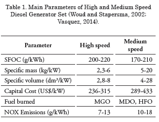
Conventional Diesel electric propulsion for PSVs uses high speed Diesel generator sets because of its low initial costs and low mass. However, medium speed Diesel generator sets off ers lower operational costs. In Table 1 the main diff erences between Diesel generator sets are presented.
Methodology
Arrangements for evaluation
The four electric propulsion arrangements for analysis are illustrated in Fig. 2.
The Diesel generator sets are represented by the empty rectangles connected to the generators; the switchboards receive the power from the generator sets for distribution to the vessel loads. Each switchboard section supplies power to one of the main propulsion drives, to one of the dynamic positioning drives, as well as to the half of the auxiliary and hotel loads (represented by the arrows). Since the batteries bank are connected to the switchboard in two arrangements, their connection is represented by dashed lines.
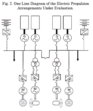
The arrangement 1 has high speed generator sets, the arrangement 2 has medium speed generators, the arrangement 3 and 4 are the same as the 1 and 2, respectively, but with the batteries bank connected to each section of the main switchboard.
Methodology
The methodology to analyze the electric propulsion arrangements is presented in Fig. 3.
Th e starting point is the basic hull form of a PSV, from which the resistance to advance is estimated. Afterwards, the propulsion power is obtained. Next, the four electric propulsion arrangements are sized. Th e main properties of the arrangements, namely mass, volume and acquisition costs are compared. Later, a performance analysis for each arrangement is made by simulating the power demand from the PSV for a typical service. Th e fuel consumption and exhaust emissions (NOx, SOx and CO2) for every arrangement are estimated. Finally, a comparison between arrangements is made to determine the eff ect of the medium speed Diesel engines and the batteries bank in the fuel consumption and the exhaust emissions.
Propulsion power and arrangement sizing
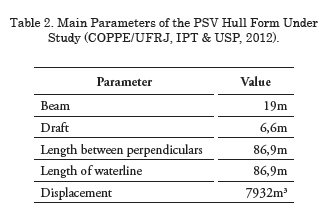
The case study is the basic hull form of a conceptual design of a PSV for the pre-salt oil fields at Santos Basin (Weiss, et al., 2012). The project is conceived for a service speed of 15 knots, a total capacity of 4500DWT and is required to have Diesel Electric propulsion system with dynamic positioning system classified as class 2. The main parameters of the PSV are shown in Table 2.
Propulsion power estimation
The main input for power estimation is the vessel resistance. Besides, characterization of similar vessels is conducted to have as much information to be used as a guide for the alternatives.
Resistance to advance
The resistance is obtained for all the speed range (from 1 to 15knots) and for two conditions: for laden voyage i.e. 100%∇ and partial load voyage i.e. 75%∇. The above is made using a spreadsheet based in the statistical methodology proposed by Holtrop and Mennen (1982) and Holtrop (1984). The results are increased by 15%, considering the resistance margin. The final resistances for the PSV are: 400kN for laden voyage and 314kN for partial load voyage, both at 15knots (Vasquez, 2014).
Characterization of similar vessels
The characterization was performed considering 32 electrically propelled PSVs which are operating in Brazil (see details in Vasquez, 2014). From the characterization, it was seen that the used prime mover is the High Speed Diesel Engine at 1800rpm; the rated voltage is 690V or 480V at 60Hz; the vessels have two Z-drive azimuth thrusters for main propulsion with FPP or CPP with or without nozzles. The nozzle or propeller diameters drops within 36% to 68% of the design draft. From the characterization an expression to estimate the mass for a conventional Diesel electric propulsion system for PSVs was obtained (Vasquez, 2014):
![]()
Where MDE is the mass of the electric propulsion system in kg and Pp is the total propulsion power in kW.
Propulsion power estimation
The propulsion power is estimated considering the following conditions (Vasquez, 2014):
• Propulsion units: Z-drive nozzled azimuth thrusters.
• Propeller and nozzle: Ka 4.70, FPP propeller and 19A nozzle. Propeller+nozzle diameter is limited to 65% of the design draft. Considering commercial nozzle diameter, propeller diameter must be lower than 3,46m.
The closest commercial diameter for propeller is 3,4m. Pitch to diameter ratio is fi xed as 1,2.
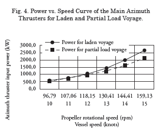
The torque, thrust, propeller rotational speed and required input power are obtained using the systematic series for the selected propeller and nozzle (Bose, 2008) along with the propulsion coeffi cients proposed in Holtrop and Mennen (1982) and Holtrop (1984) for twin screw vessels. Th e maximum required power at the input of each propeller including 5% mechanical losses of the thruster (Muller, 2008) is 2663kW at 1200rpm. Fig. 3 shows the required power vs. speed curve for each azimuth thruster for speeds from 10 to 15 knots at the two operational conditions. Finally, the power margin is settled as 10%, according to the recommendations in literature (Brinati, 2011). As a result, each electric motor for propulsion must deliver at least 2929kW.
Arrangement sizing
Design specifi cations
The electric propulsion arrangements should comply with rules established by classifi cation societies and the IMO about pollutant emissions and redundancy requisites.
Pollutant emissions
Th e MARPOL 73/78 annex VI limits the NOx emissions of Diesel engines operating at 1800rpm to a maximum of 7,8g/kWh, for the ones at 900rpm the limit is 9,2g/kWh. Th e SOx are limited by settling a maximum sulfur content for fuel of 3,5% (IMO, 2004).
Dynamic positioning system
Th e vessel is required to have a dynamic positioning system class 2 (IMO, 1994). According to the IMO, the electric propulsion arrangement must be split into two sections connected between them by bus tie breakers. Furthermore, the thrusters intended to operate as side thrusters for dynamic positioning must be doubled along with their associated equipment.
Voltage level
The voltage level for every arrangement is settled as 690V, 3phase, 60Hz according to the recommendations from IEEE (2002), section 4.4.
Arrangement sizing
Component Sizing
The induction motor for main propulsion must meet the following conditions:
• Rated output power ≥ 2929kW
• Rotational speed ≤ 1200rpm
• Rated voltage = 690V
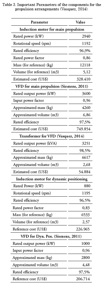
A commercial motor is selected from a catalog. Its important features are shown in Table 3. It should be noted that there are two motors for main propulsion.
The induction motors for the two bow thrusters must provide maximum 830kW, each, for dynamic positioning under design conditions. In these conditions, the main propulsion units acts as stern thrusters providing maximum 156kW each, as shown in Fig. 5. Th e main parameters of the selected motors for the bow thrusters are presented in Table 3.
The characteristics of the VFDs and transformers for main propulsion system and the VFDs for the dynamic positioning system are detailed inTable 3. It must be taken into account that each component is doubled.
Power request from auxiliary loads
The power request from auxiliary/hotel loads (pumps, navigation equipment, HVAC, compressors, etc.) was estimated from a detailed load balance presented in Arcoverde (2013).
Total electrical demand
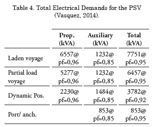
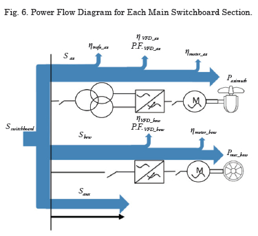
The total power demand from one section of the main switchboard is estimated considering the power flow shown in Fig. 6. The losses (efficiencies) are defined as ηx, power factors as P.F.x, active power as Px and apparent power as Sx.
The total apparent power distributed by each switchboard section is composed by active and reactive components. In Table 4, the total power demands for each type of operation are shown.
The required current rating for each switchboard section is 3242A. The commercial unit with closest rating is 4000A, which has an estimated mass equal to 700kg, volume of 8,44m3 and an efficiency of 99,5%.
Diesel generator sets
The maximum power demand corresponds to laden voyage. Considering 4 Diesel generator sets, the minimum power rating for each generator set is 1850kW and 1948kVA, respectively.
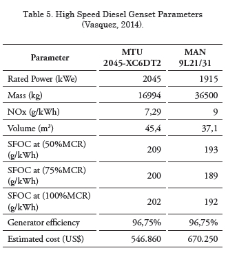
For the high speed unit of the arrangement 1, the MTU 2045-XC6DT2 meets the conditions. For the medium speed unit of the arrangement 2, the MAN 9L21/31 is a good choice. Their main characteristics are shown in Table 5.
Sizing of batteries bank for arrangements 3 and 4 The batteries bank are added to arrangement 1 and 2, becoming the arrangement 3 and 4, respectively. The batteries bank is implemented with the objective of compensating the lack or excess of power in order to keep the Diesel engines working at their optimum operational point. Furthermore, they are also sized to supply the required power while the vessel is in port. The sizing process is considered the same for both arrangements.
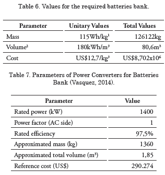
The storage capacity is determined as 14504kWh (Vasquez, 2014). The main parameters of the ZEBRA batteries are shown in Table 6, as well as their values for the required storage capacity.
The batteries bank requires a power converter with bidirectional power flow capability and AC/DC conversion. The main features of the converter are shown in Table 7.
Mass, volume and capital cost comparison
The mass and volume for each arrangement are shown in Fig. 7. The first element corresponds to the mass prediction obtained with Equation 1.
Capital costs are also presented in Fig. 8; they do not include the cost of azimuth thrusters.
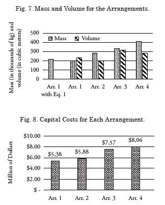
From the figures, the following analysis can be performed:
• The mass obtained with Equation 1 is 11% greater than the estimated mass of the arrangement 1. The formula gives reasonable values which can be used for early stages of project design of this type of ship.
• The arrangements with medium speed Diesel engines presented higher mass than arrangements with the high speed ones. The difference can exceed the 200% (more than 200ton)
• The above implies that less payload can be transported by a PSV with Diesel electric arrangements with medium speed gensets than with high speed gensets. Moreover, the use of batteries bank can further reduce the amount of payload that can be transported.
• The acquisition costs of the arrangements are proportional to the mass.
Performance analysis
The fuel consumption and exhaust emissions from each arrangement are estimated by evaluating the performance of the Diesel engines and batteries bank. The above is made by simulating the power demand from the electrical system of the PSV for a typical service.
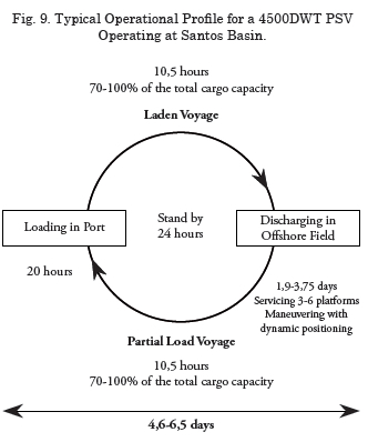
Operational profile
The typical operational profile for a PSV is divided in: loading in port, laden voyage, dynamic positioning operation, partial load voyage and standby/anchored operation. The above is depicted in Fig. 9 showing also the average duration of each service.
Load profile
The load profile for an electrically propelled PSV with 4500DWT serving the Santos Basin is constructed using the time periods presented in Figure 8, the maximum load demands shown in Table 4 and the operative conditions of a high deadweight PSV described in Murta and Suzano (2013) and Medeiros (2010).
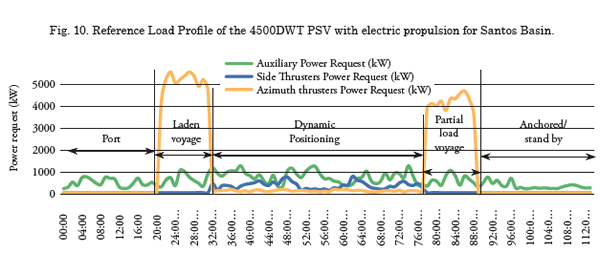
The load profi le for a complete service of the electrically propelled PSV for the Santos Basin is depicted in Fig. 10. Th e duration of each type of operation is indicated in the fi gure.
Fuel consumption
The fuel consumption is determined using the power fl ow in Fig. 11 as reference. Th e load profi le is the input and the power that each Diesel engine must deliver is obtained computing the losses of each component. Th e mass of the fuel required to produce the demanded power in each sample is defi ned by:
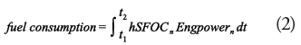
Where h is the number of Diesel engines in operation, SFOCn is the engine specific fuel consumption correspondent to the delivered power; Engpowern is the power delivered by all Diesel engines in kW, t1,2 are the time limits between samples and the sub index n is the number of the sample. Th e fuel consumption is given in grams.
The SFOC curves for the engines of arrangements 1-3 and 2-4 are shown in Figure 11. Th e SFOC curves vary as a function of engine loading. Th e lowest value is when the loading is between 70- 90% of the MCR.

The power delivered by the Diesel engines is determined assuming that each generator set delivers the same power. Furthermore it is considered that the energy compensation from batteries is mainly focused for dynamic positioning, stand by and port operations.
During dynamic positioning and stand by, the batteries are operating along with Diesel engines or without them. When both are in operation, the Diesel engines are maintained loaded at their optimal operating point (in which the SFOC is lowest) while the batteries compensates the lack or excess of power by delivering/taking energy. When the batteries are fully loaded, the Diesel engines are shut down and only batteries are supplying energy. For port operation, the PMS only allows the batteries to supply energy until their depletion.
During laden and partial load voyage the batteries are mainly taking energy; however, they keep the engines loaded at their optimal operating point.
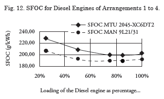
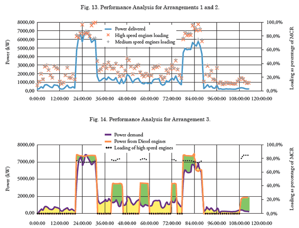
Fig. 13 shows the loading and the delivered power from Diesel engines of arrangements 1 and 2. Fig. 14 depicts the power demand from arrangement 3; in this figure, the energy provided by the batteries is represented by the yellow areas while the energy taken is shown by the green areas. For the arrangement 4, a similar behavior as Fig. 14 is expected.
From the figures it can be noted that the loading of the Diesel engines for arrangements 1 and 2 is below 50% for more than 80% of the total service time. While in the arrangement 3, the Diesel engines are mostly loaded between 75% and 85%. In fact, for arrangements 1 and 2, the average loading of engines is 50% with a standard deviation of 28,8%. For arrangements 3 and 4 the average loading of engines is around 80,9% with a standard deviation of 1,7%.
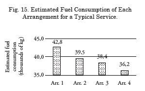
Fig. 15 presents the estimated fuel consumption for a service with the operational profile presented in Fig. 9.
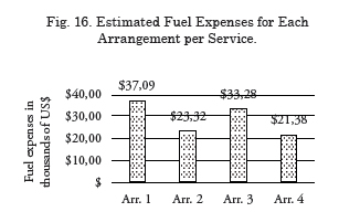
Since the high speed Diesel engines burn MGO and the medium speed ones are fueled with HFO, the fuel expenses per service are shown in Fig. 16. Fuel prices were taken from Petromedia (2014) at 18-08-2014 referenced at the port of Singapore.
Exhaust emissions
The exhaust emissions from Diesel engines considered for estimation are the Nitrous Oxides (NOX), Sulphur Oxides (SOX) and Carbon Dioxide (CO2), which are the most studied emissions from ships in the literature (Cisneros, 2012; Corbett and Koehler, 2003). The exhaust gases can be obtained applying power based factors (in g/kWh) or fuel based factors (kg/ tonne of fuel burned) (Dedes, Hudson and Turnock, 2010). In the case of the NOX emissions, they are specific for each motor and are usually defined using power based factors (in g/kWh) depending on the energy delivered by the engine.
The mass of NOX released to the environment can be approximated by:
![]()
Where, efNOx is the NOx power emission factor given in g/kWh, NOX is the total mass of NOx released in g.
The SOX and CO2 emissions are defined using fuel based factors, thus, they depend on the mass of fuel burned. Regarding the SOX emissions, they also depend on the sulfur content in the fuel. The mass of SOX and CO2 released to the environment are defined as following:
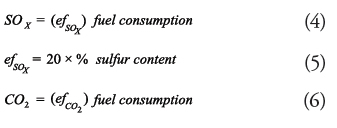
Where, %sulfur content is the sulfur content of the fuel as a percentage of the total mass or volume, efSOx is the SOx fuel emission factor in kg per 1000kg of fuel burned, efCO2 is the CO2 fuel emission factor in kg per 1000kg of fuel burned. The SOx and CO2 mass is given in kg.
The exhaust emissions are obtained for each arrangement assuming the following:
• The sulfur content of the MGO is settled as the maximum admissible: 1,5% (IMO, 2004).
• The sulfur content of the HFO is settled as the maximum permitted by the MARPOL 73/78 Annex VI, 3,5% (IMO, 2004).
• The CO2 emission factor is 3190kg per each 1000kg of fuel burned, disregarding the engine type and the fuel type.
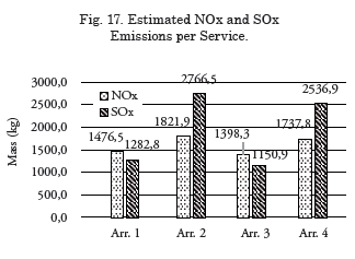
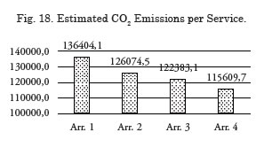
Taking into account the above equations and conditions, as well as the performance analysis and fuel consumption of section 5.3, the exhaust emissions from each arrangement for a typical service are shown in Fig. 17 and 18.
Comparison of fuel consumption and exhaust emissions of each arrangement
From the previous results for the 4 arrangements, the following analyses can be made:
• Owing to the low SFOC, the fuel consumption of the medium speed generator unit is significantly lower than the fuel consumption of the high speed ones. The differences range between 5,5% (2200kg) to 8,3% (3300kg).
• The reduction in fuel consumption can lead to reduce the space dedicated for fuel storing, allowing to be used for payload transport. Nevertheless, for the present case, the additional payload transport would not be higher than 3300kg, which does not compensate the additional 78000kg of the medium speed generator sets.
• It was seen how the operational point of the Diesel engine, influences the fuel consumption. The arrangements where the Diesel engines were optimally loaded, presented lower fuel consumption than the other arrangements.
• The use of batteries bank along with high speed Diesel generator sets have shown better results in reduction of fuel consumption that the arrangements with medium speed units. The fuel reduction between arrangements 1-3 was approximately 4400kg, whereas for the arrangements 2-4 the reduction was 3300kg.
• Although the potential fuel reduction with the use of batteries in electric propulsion arrangements, their additional mass reduces significantly the payload that can be transported. For this case, the capacity of the PSV will drop by 129ton.
• The arrangements with medium speed units presented US$11.000 of less fuel expenses compared with the arrangements with high speed units. The difference between arrangement 4 and arrangement 1 is greater than US$15.000 per service. Assuming 6 services per month, the economies can reach up to US$1’080.000.
• The CO2• Regarding the NOx emissions, they are related to the energy delivered by the Diesel engines; the NOx values are neither influenced by the loading of the Diesel engines nor the reduction of the fuel consumption. Therefore, the difference of NOx emissions between arrangements was not higher than 30kg. and SOx emissions were seen proportional to the fuel burned. In the case of SOx emissions, they are also dependent on the fuel type.
• Regarding the NOx emissions, they are related to the energy delivered by the Diesel engines; the NOx values are neither influenced by the loading of the Diesel engines nor the reduction of the fuel consumption. Therefore, the difference of NOx emissions between arrangements was not higher than 30kg.
• Taking into account the effects of the batteries bank over the loading of the Diesel engines, they are a good alternative to reduce the fuel consumption of the vessels. As a consequence, the CO2 and SOx released to the environment can also be reduced by its implementation.
Conclusions
The influence of medium speed Diesel generator sets and batteries bank over fuel consumption and exhaust emissions in electric propulsion systems in PSVs was evaluated.
The medium speed Diesel generator sets shown an important reduction in fuel consumption and fuel expenses of the electric propulsion arrangements when compared with high speed Diesel generator sets. Nonetheless, the additional mass and acquisition costs of the arrangements with this type of generating set unit could produce a negative effect over the lifecycle cost of the project. The NOx and SOx emissions increased with this type of Diesel engine.
The reduction in the fuel consumption by the use of energy storage system was demonstrated. In fact, it was seen that the batteries kept the Diesel engines loaded at their optimum operational point, burning less fuel per unit of energy when compared to the conventional electric propulsion arrangements. In this context, the batteries stand as an important alternative to reduce the impact of the exhaust emissions by decreasing the fuel burned and, consequently, the CO2 and SOX emissions. Nevertheless, batteries present significant increments in mass, volume and capital costs.
The economic impact of the above technologies require a feasibility study in order to establish if the reduction in fuel consumption compensates the lower incomes due to lower payload.
Regarding the exhaust emissions, the approach used in the present work was fuel-based factors for the estimation of the SOx and CO2 emissions; while for the NOx emissions the estimation was made using power based factors. Consequently, the NOx emissions were slightly affected by the reduction of the fuel consumption. With respect to the CO2 and SOx emissions, they are strongly dependent on the amount of fuel burned, since the fuel-based factor is related to the fuel consumption.
References
ADNANES, A. K. Maritime Electrical Installations and Diesel Electric Propulsion. ABB AS Marine and Turbocharging Tutorial Report, 2003. From: <www.abb.com/marine>. Retrieved: October 2013.
ARCOVERDE, F. Avaliação de Sistemas Diesel Elétrico, Mecânico e Híbrido para embarcações de Apoio a Plataformas. Universidade Federal do Rio de Janeiro. Rio de Janeiro, p. 87. 2013.
ASPIN, J.; HAYMAN, S. The Hybrid Tug Reality - The Business Case for Green Technology in the Tugboat Industry. Tugnology'09. Amsterdam: ABR Company Ltd. 2009.
BOSE, N. Marine powering Prediction and Propulsors. New York: Society of Naval Architects and Marine Engineers, 2008.
BRINATI, H. PNV5753: Topicos Especiais em Instalações Propulsoras. São Paulo: Departamento de Engenharia Naval e Oceânica da USP, 2011.
CISNEROS, J. C. M. Redução dos impactos ambientais causados por emissões de gases no transporte marítimo. Dissertação (Mestrado). Universidade de São Paulo. São Paulo. 2012.
COPPE/UFRJ; IPT; USP. Pacote Nacional de Projeto e Maquinário de Embarcações de Apoio Marítimo à Produção de Petróleo no Mar - SBBR - Segundo Relatório. Universidade Federal do Rio de Janeiro, Instituto de Pesquisas Tecnológicas e Universidade de São Paulo. São Paulo. 2013.
CORBETT, J.; KOEHLER, W. Updated Emissions from ocean shipping. Journal of geophysical research, v. 108, p. 9.1 - 9.13, 2003.
DEDES, E. K.; HUDSON, D. A.; TURNOCK, S. R. Assesing the potential of hybrid energy technology to reduce exhaust emissions from global shipping. Energy Policy, n. 40, p. 204- 218, 2012.
DEDES, E.; HUDSON, D.; TURNOCK, S. Design of Hybrid Diesel-Electric Energy Storage Systems to Maximize Overall Ship Propulsive Efficiency. 11th International Symposium on Practical Design of Ships and Other Floating Structures. Rio de Janeiro: Universidade Federal de Rio de Janeiro. 2010. p. 703-713.
HOLTROP, J. A Statistical Re-Analysis of Resistance and Propulsion Data. International Shipbuilding Process, v. 31, n. 363, 1984.
HOLTROP, J.; MENNEN, G. G. J. An Approximate Power Prediction Method. International Shipbuilding Progress, v. 29, n. 385, 1982.
IEEE. IEEE std. 45 - Recommendend Practice for Electric Installations on Shipboard. New York: The Institute of Electrical and Electronics Engineers, 2002.
IMO. Guidelines for Vessels with Dynamic Positioning Systems - Circular 645. London. 1994.
IMO. MARPOL 73/78 Annex VI: Prevention of Air Pollution from Ships. International Maritime Organization, 2004. From: <www. imo.org>. Retrieved: January 2014.
MAN. Diesel-electric Propulsion Plants: A brief guideline how to engineer a diesel-electric propulsion system. MAN Diesel & Turbo, 2012. From <http://mandieselturbo.com/ f iles/news/f ilesof17642/Diesel-Electric- Propulsion-Plants-Engineering-Guideline. pdf>. Retrieved: August 2014.
MANZONI, R.; METZGER, M.; CRUGNOLA, G. ZEBRA Electric Energy Storage System: From R&D to Market. HTE hi.tech.expo 2008. Milán: [s.n.]. 2008.
MEDEIROS, F. P. D. Avaliação das emissões de poluentes associadas ao transporte marítimo na exploração e produção de petróleo na Bacia de Campos. Dissertação (Mestrado). Pontifícia Universidade Católica do Rio de Janeiro. 2010.
MULLER, J. Propulsion Solutions for All Electric Ships - Schottel. Ingenieros Navales, 2008. From: <http://www.ingenierosnavales.com/ sesiones/documentacion/SCHOTTEL%20 propulsion%20solutions.pdf>. Retrieved: December 2013.
MURTA, A. L. S.; SUZANO, M. A. Uma Metodologia Para o Dimensionamento de Frota de Embarcações de Apoio "PSV" para Atender uma Dada Demanda de Suprimento de Combustível, Considerando Algumas Plataformas "Offshore". Sustainable Business, Rio de Janeiro, n. 24, p. 1-15, Fevereiro 2013. ISSN 1807-5908.
PETROMEDIA. bunkerworld latest prices. Bunkerworld, 18 ago. 2014. From: <http:// www.bunkerworld.com/prices/>. Retrieved: 18 ago. 2014.
SIEMENS. SINAMICS S120, S150 - Catalog D21.3. Nuremberg, Germany: Siemens, 2011.
VASQUEZ, C. A. M. A methodology to select the electric propulsion system for Platform Supply Vessels. Dissertation (Master). Escola Politécnica da Universidade de São Paulo. São Paulo, 2014.
WEISS, J. et al. Desenvolvimento de supply boats para operações na Bacia de Santos. 24° Congresso Nacional de Transporte Aquaviário, Construção Naval e Offshore. Rio de Janeiro: SOBENA. 2012. p. Artigo 069.
WOUD, H. K.; STAPERSMA, D. Design of Propulsion and Electrical Power Generation Systems. London: Institute of Marine Engineers, 2002.
_____________________________________________
1 Dedes, Turnock and Hudson (2012).
2 Manzoni, Metzger and Crugnola (2008).
3 Dedes, Turnock and Hudson (2012).