Hull girder: Forced vibration analysis by propeller excitations
Viga buque: Análisis de vibraciones forzadas por excitaciones de la hélice
Franklin Domínguez1
Abstract
The non-uniform wake around the propeller generates fluctuating forces on the propulsion shaft. This article presents a methodology used for the forced vibrations analysis of hull girder due to this propeller excitation. This approach is applied to a research boat considering the propeller working in the operating range using a finite element model including all ship structures, rudder, and propulsion lines with their respective supports. Added mass and damping in all submerged elements were also considered. Vibration levels acting in the vessel structure are compared with the limits proposed by ISO 6954 (2000).
Key words: lateral vibration, finite element model.
Resumen
La estela no uniforme alrededor de la hélice genera fuerzas fluctuantes en el eje de propulsión. Este artículo presenta una metodología usada para el análisis forzado de vibración de la viga buque debida a esta excitación de la hélice. Este procedimiento es aplicado a una lancha de investigación usando el método de elementos finitos incluyendo todas las estructuras de la nave, timón y líneas de propulsión con sus respectivos apoyos, considerando la hélice en el rango de operación. La masa añadida y amortiguamiento de todos los elementos sumergidos también se consideran en el análisis. Los niveles de vibración obtenidos en la estructura de la embarcación se comparan con los límites propuestos por ISO 6954 (2000).
Palabras claves: vibración lateral, modelo de elementos finitos, modos de vibración de viga buque.
Date Received: September 27th 2014 - Fecha de recepción: Septiembre 27 de 2014
Date Accepted: December 10th 2014 - Fecha de aceptación: Diciembre 10 de 2014
________________________
1 Ingeniero naval. Tecnavin S.A. Ecuador
............................................................................................................................................................
Introduction
Dynamic propeller forces need to be included to accurately verify that the hull girder supports all loads acting on it. Th ese forces are a function of thrust, torque, and propeller frequency. Namely, it is a function of: i) rotational speed for fi xed pitch propellers, and ii) pitch angle for controllable pitch propellers.
In the present work, Finite Element Method was used to estimate the deformation due to these forces acting over the hull girder. Th is method allows modeling hull girder considering all structural elements and the propeller dynamic forces. Numerical results expressed in RMS speed of vibration are compared to the limits proposed by the Classifi cation Societies.
Finite Element Method Applied to the Hull Girder
Th ere are several recommendations for the development of a Finite Element Model (FEM), especially by Classifi cation Societies, in the present work; it was necessary to include mass and inertia of the structural elements of hull and superstructure, incorporating machinery foundations for hull girder vibration analysis.
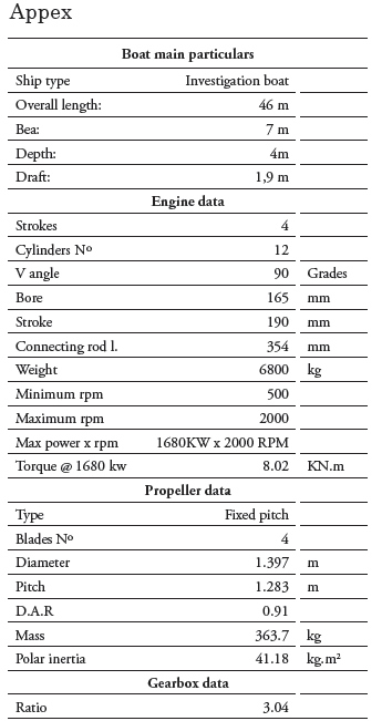
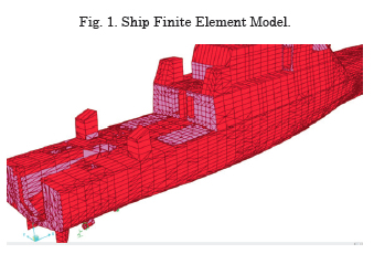
Shell elements were used in the hull and in primary structures, and frame elements to model the secondary structures and pillars, see Figs. 1 and 2. Th e mass of the structure, equipment, tank liquid, and the added mass values of 40 and 20 [kg/m2] on decks and sides respectively were distributed onthe corresponding nodes following Germanischer Lloyd (GL) recommendation.
Hydroelastic Hull Behavior
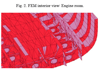
Restraints were placed to simulate the ship behavior into the water, using an equivalent spring system placed in the submerged surface of the hull to balance the ship weight. Spring stiff ness was calculated using the volume of water displaced within specifi c sections, see Fig. 3. To verify that the restrictions are conveniently applied, each node deformation was verifi ed using static weight of the vessel.
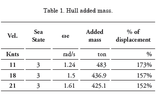
Hull added mass estimation
On elements that are submerged in water vibration moves a small fl uid volume; its mass is called added mass. This mass is added to FEM model as a distributed mass over all submerged elements.
The added mass can be obtained from Seakeeping analysis for each speed and sea state [Lewis, FM 1929]. This mass is a function of the vessel encounter frequency,
![]()
Where ωe = Encounter frequency (rad/s), ω = Wave frequency (rad/s), g= Gravity acceleration (m/s2), U = Ship speed (m/s), and μ = Wave incidence angle (rad)
Added mass values for three different ship speeds with the same sea state 3 and following seas are shown in Table 1.
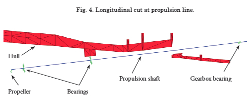
Propulsion Line Behavior
The propulsion line transmits the thrust of the ship as well as the exciting forces from the propeller. It’s lateral, axial, and torsional natural frequencies need to be considered to assess resonance. Figs. 4 and 5 show the FEM propulsion line included in this analysis.
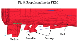
Bearings location
Cutless bearings or roller bearings are included in our FEM model. Usually, bearing center is the support point, except for bearing close to the propeller, which is considered to 1/3 from the aft end of bearing.
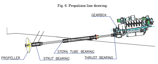
The propulsion line natural frequencies depend on bearing position and stiffness. In the present study, 3 bearings were used, as shown in Fig. 6. Two aft supports are bronze – rubber cutless bearings. The propeller shaft had been modeled using beam elements. The propeller and flanges masses are included in their respective locations. The manufacturer provided the bearing stiffness value for accurate results.
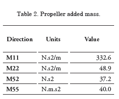
Propeller added mass
The propeller accelerates its surrounding water and an added mass is generated, that was estimated using PRAMAD program [U OF MICHIGAN, 1980]. There are several formulas for estimating these masses M. Parsons (1980), Schwanecke (1963) or D. MacPherson (2007).
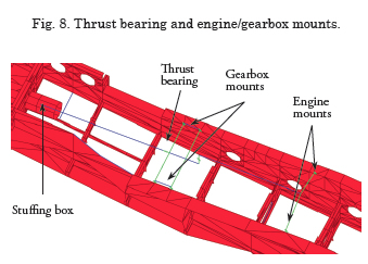
Thrust bearing and engine/gearbox flexible coupling Stiffness
In our model, thrust bearings are placed on the gearbox; and flexible mounts of gearbox & engine with the stiffness provided by manufacturer. Mounts properties were modeled for each direction (x , y , z). Fig. 8 shows the position of the elements used.
Natural vibration analysis
Once the mentioned hull and propulsion line properties are modeled, vibration analysis can be performed for both, hull girder and propulsion line natural frequencies.
The FEM and the eigenvalue matrix method had been used to calculate the propulsion system vibrational modes. The finite element method divides a body in finite elements interconnected by nodes, which are equivalent to the original body; in the elastic zone the equations to find the nodes deformation can be expressed in matrix form as follows:
![]()
where:
[M] is the mass matrix of the system
[K] is the stiffness matrix of the system
{Y} is the displacement vector
{Ÿ} is the second derivative of displacement Y
Nowadays, computers allow this calculation accurately and for several degrees of freedom.
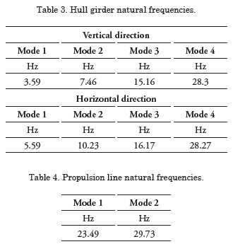
Tables 3 and 4 present the natural frequencies in the system working range.
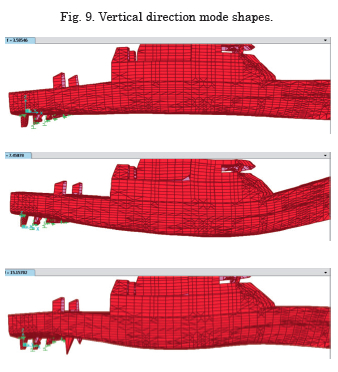
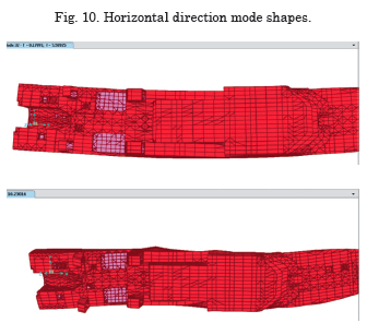
Figs. 9 and 10 show the modal shape of natural frequencies.
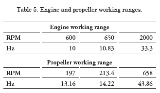
It is recommended that the working range has to be from 650 RPM to 2000 RPM on engine, due to coincidence between hull girder natural frequenciesand engine and propeller excitation range as can be seen in Table 5.
Figs. 11 and 12 show the natural frequencies mode shape found in the propulsion line. It should be noted that the fi rst vibration mode is at the tunnel between Stern tube bearing and gearbox and the second mode at the propeller end. Th e fi rst axial natural frequency is 37.77 Hz.
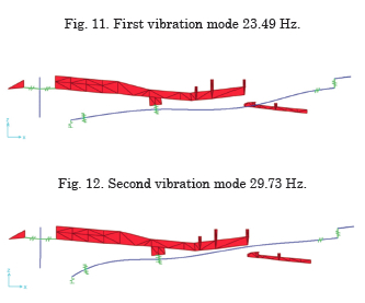
Propulsion line natural frequencies are within the working range and forced analysis should be considered to check the structures resistance and whether the proposed vibration levels standards are met.
Damping
Energy due to vibration on the ship can be dissipated as damping. Vibration analysis should consider three types of damping, namely: the propeller damping, the hysteresis damping and hull damping in water.
Propeller damping
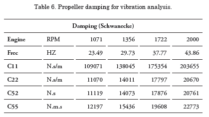
Damping is generated when the propeller rotates in the water, the approximation of these values are shown in Schwanecke (1963) or M. Parsons (1980). The damping depends on the propeller rotation speed, therefore is determined for each operating condition, see Table 6. The damping is placed on the propeller node in the FEM. Structural deformations caused by the propeller excitation forces decreases due to the damping effect.
Structure damping
Hysteresis damping is caused by internal molecular friction on vessel structures, and its value is estimated using a coefficient 0.05 proportional to the stiffness.
Hull damping
Ship motion generates a damping (B33) which can be obtained from Seakeeping for each speed and sea state under study. These results are applied to the submerged hull.
Transmissibility
Flexible mounts reduce vibration effect produced by the engine on their foundations. In the case of study, the propulsion system has 2 front flexible rubber mounts for each engine and 2 flexible mounts for each gearbox.
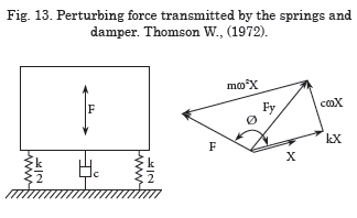
Transmissibility is the relationship between the perturbing force and the transmitted force to the foundation and depends especially of the connection stiffness between the engine and the boat structure. For this study, flexible rubber mounts had been used.
There are several references that provide recommendations to know whether a particular mount is suitable to reduce engine forces transmission to structures. W. Thomson, (1972), shows a graph that has frequency (cpm) and the static deformation produced by the engine on the flexible mount or the connecting element as variables.
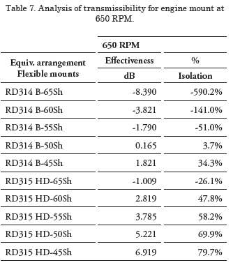
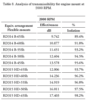
For the present study, the engine manufacturer provides several options for flexible mounts, tables 7 and 8 show the percentage of effectiveness of the system foundation.
According to transmissibility analysis results had been decided to use the 315 mount - 55SH due to the appropriate reduction of excitation forces transmitted by the engine and therefore these forces will not be considered in the analysis of vibration of the boat.
Forces and moments of propeller excitation
Propeller vibration forces are predominant in calculating propulsion line and boat structure vibration. These forces occur due to non-uniform water flow in the propeller creating periodic forces depending on the number of blades called propeller excitation forces. These forces are generated in the vertical, transverse and longitudinal directions.
Forces transmitted to the propulsion shaft (bearing forces)
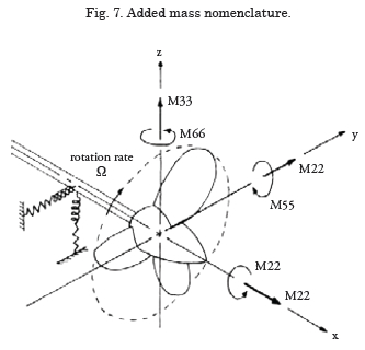
For lateral vibration analysis (bending) should be considered vertical forces F33 and transverse F22 and their moments M33 and M22, while for the axial analysis the longitudinal force F11 is considered, following same nomenclature shown in Fig. 7.
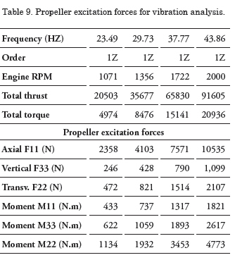
Exciting forces are decomposed into harmonic components using the Fourier analysis [Kumai, 1961]. Currently, Classification Societies recommend excitation values for each order based on the number of blades and thrust or torque on the propeller, as appropriate. For the study boat, the excitation values recommended by ABS (2006) had been used. The values of the forces applied to the study boat in 4 different working conditions are shown in Table 9.
Hull pressure forces (pressure fluctuation)
There are several causes that produce fluctuating pressures on the hull in the area of the propeller. These pressures fluctuate proportional to the propeller rotation speed, its number of blades (blade rate frequency), and cavitation.
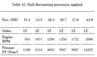
Pressures can be obtained by experimentation, by numerical approximation (CFD) or by empirical formulas (Holden, 1980). For the current analysis, Holden formulas were used. These pressures vary according to working condition. Table 10 shows pressures values applied in an area of 1 m2 of each propeller, in all working conditions analyzed.
Working conditions to evaluate
For this study case, the reduction ratio is R = 3.04, and a 4 blades propeller was used. Therefore, the excitation will occur at a frequency:
![]()
Generally, the two first orders of the propeller excitation are considered: 1Z and 2Z, due to lower excitation magnitudes presented by higher orders.
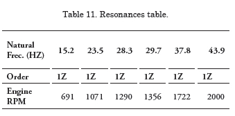
Resonance conditions between the excitation frequency and propulsion line natural frequencies had been analyzed. Additionally maximum working condition (MCR) had been analyzed, which in this case is 2000 RPM.
The following table shows the resonances to consider
Rudder Line Behavior
Vibration analysis must consider the rudder behavior, to check if there is any resonance in the working range. Additionally it is important to know if the rudder holds up propeller fluctuating stress loads.
Rudder supports location
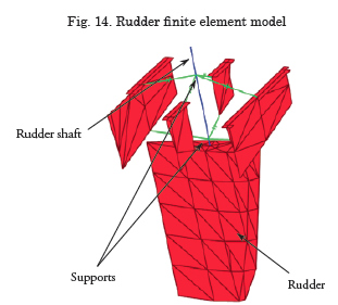
Rudder supports are usually cutless bearings. The FEM represents these supports in the corresponding directions. In the present study, rudder has two supports, upper one restricting rudder shaft axial movement and allowing only rotation and lower support. Due to the rudder shaft is modeled with frame element; constraints simulating the contact between the flanged shaft and the rudder shell had been included.
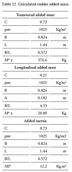
Rudder added mass
Rudder is also immersed in water and its added mass is considered in the FEM. Rudder is considered as a plate to find the rudder added mass. Mukundan (2002) method was used and its values are presented in Table 12. The rudder added mass was evenly distributed at nodes on rudder surface in their respective directions.
Classification Societies Acceptance criteria
Classification Societies recommend limits for vibration velocity for crew, passengers, structures and machinery areas.
These limits are recommended to ensure people comfort in the accommodation areas and to prevent fatigue failure in local structures.
Living areas limits
Classification Societies recommend limits depending on craft type and accommodation or work sectors.
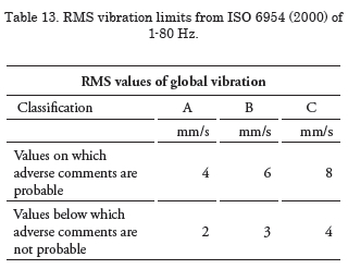
ISO 6954 (2000) proposed by Classification Societies such as ABS and Germanischer Lloyd had been taken as acceptance criteria for the evaluation of the study boat.
On Table 13, the classification refers to the area of application:
• A Class: is for passenger cabins,
• B Class for accommodation of crews and
• C Class for workspaces
There are voluntary limits known as comfort notations, which are limit values proposed by the Classification Societies to grant class notations, especially for passenger vessels.
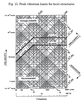
Structure limits
There are vibration limits for not accommodating areas as tanks, mast, lazaretto structures, engine room, etc. These limits seek to avoid structural damage due to fatigue and the cracks occurrence due to vibration. Fig. 15, taken from ABS (2006), shows vibration peak limits for structures bellow which the risk to fatigue crack is expected to below. From Fig. 15 can be seen that for frequencies between 5 Hz and 10 Hz vibration peak limit recommended is 30 mm/s.
Hull structure and deck house forced analysis evaluation
Finite element method was used to perform a forced vibration analysis of the hull structure, using the following equation:
![]()
where [M] is the mass matrix of the system, [K] is the stiff ness matrix of the system, [C] is the damping matrix system, {Y}: is the displacement vector, {?}the fi rst derivative of displacement Y, {Ÿ} is is the second derivative of displacement Y, {F}: is the excitation force vector.
Deformation was estimated at all nodes in the model, for each load condition. Figs. 16, 17, 18 and 19 graphically show deformation results.
Harmonic motion deformation as the case of vibration can be represented as follows, at any time t:
![]()
where:
A = deformation amplitude (m)
ωv= Vibration frequency (rad/s)
t = time (s)
Since the speed is the relationship between the deformation and the time, the vibration speed magnitude (V) can be obtained by the following equation:
![]()
Figs. 16, 17, 18 and 19 show as color-sectors the deformation that is proportional to vibration speed. Th ere is greater deformation on aft bulkhead of upper deck house at 43.86 Hz condition.
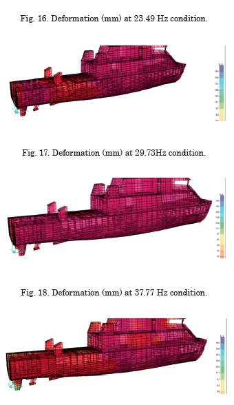
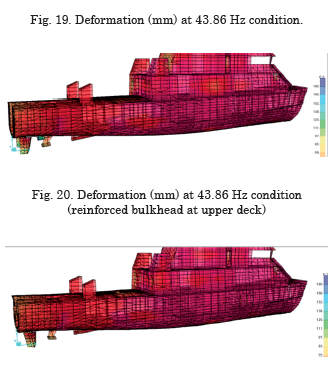
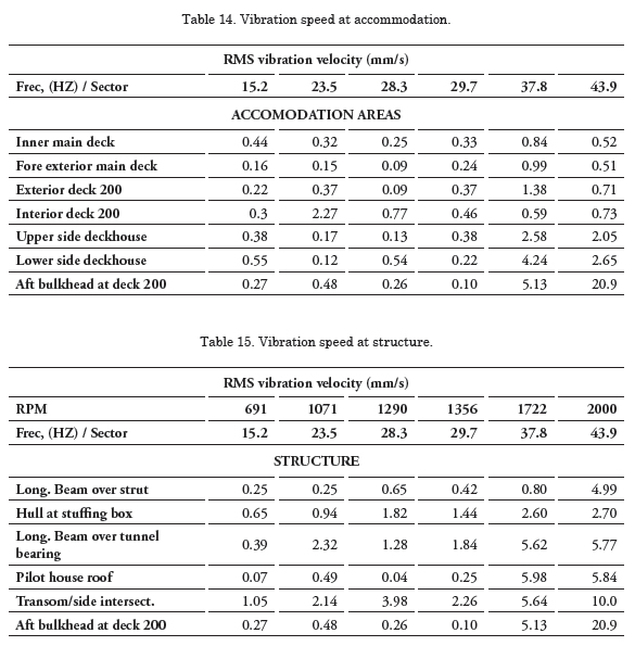
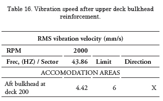
Fig. 20 shows the deformation in the same scale as the previous figures and shows the deformation decrease on aft bulkhead at upper deck, with respect to Fig. 19. This improvement can be seen in Table 16.
Conclusions
• Acceptance criteria are effective, so the best way to avoid resonance problems is configuring the propulsion system to keep vibration below criteria.
• Natural frequencies of the propulsion line need to avoid the working range to prevent resonances.
• Natural frequencies of ship panels and structure need to avoid the working range of propeller excitation forces.
• Forced vibration analyses on hull girder including propeller excitation forces should be performed to identify sectors that do not meet standards.
• The results obtained in the design stage allow identifying possible failures, especially when there is resonance risk in the propulsion line.
Bibliography
AMERICAN BUREAU OF SHIPPING, Guidance on ship vibration, Houston, ABS, 2006.
DEPT. OF NAVAL ARCHITECTURE AND MARINE ENGINEERING OF UNIVERSTIY OF MICHIGAN, Propeller added mas and damping program (PRAMAD). Revision of September 5, 1980.
H. MUKUNDAN, Finite Element Analysis of a Rudder, Undergraduate Thesis for the completion of Bachelor of Technology in Ocean Engineering and Naval Architecture, Indian Institute of Technology, Madras, July 2002.
HOLDEN, FAGERJORD, FROSTAD, Early Design stage approach to reducing hull surface force due to propeller cavitation, SNAME Trans., 1980.
ISO, International Standard ISO 694: Mechanical vibration – Guidelines for the measurement, reporting and evaluation of vibration with regard to habitability on passenger and merchant ships, 2000.
IWER ASMUSSEN, WOLFGANG MENZEL, HOLGER MUMM, Ship vibration, Hamburg, Germanischer Lloyd, 2001
LEWIS F.M., The inertia of the Water Surrounding a Vibrating Ship, SNAME transactions, 1929.
M. PARSONS, Added mass and damping of vibrating propellers, Department of naval architecture and naval engineering University of Michigan, 1980.
RAMESWAR BHATTACHARYYA, Dynamics of marine vehicles, John Wiley & Sons, Inc., 1978.
S. QUEK, G.R. LIU, Finite Element Method: A Practical Course, Burlington MA, Elseiver Science, 2003.
SCHWANECKE H., Gedanken zur Frage der hydrodynamisch erregten Schwingungen des Propellers und der Wellenleitung, Jahrbuch STG, 1963.
T KUMAI, Some Aspects to the Propeller – Bearing Forces Exciting Hull Vibration of a Single Screw Ship, Research Inst. for Applied Mechanics, Kyushu Univ, 1961.
THOMSON W., Theory of vibration, New Jersey, Prentice Hall, 1972.