Propulsive Qualities of Catamaran Vessels
Cualidades propulsivas de buques catamaranes
José María Riola1
Abstract
During the last decade the civil and military applications of catamaran vessels have developed rapidly. Their particular area of proliferation is the short sea shipping where their power, economy, habitability and behavior have provided them a market niche. The rapid market growth ha caused catamarans to experience design modifications regarding size, speed, cargo diversity (passengers, vehicles, containers).
The purpose of this article is to show the work developed by the El Pardo Hydrodynamic Experiences Channel (CEHIPAR) regarding the propulsive qualities of catamaran vessels. This work is the result of the need expressed by the Ministry of Defense for provision of technical assistance and scientific research for an I+D program that established more adequate program parameters for a catamaran-type vessel from the propulsive point of view, in relation to its size and shape, so that it has the adequate information and trustworthiness when suggesting a vessel of this type as an alternative to other platforms, always within the scope of application of patrol-type or quick-attack-type vessels.
Key words: Catamaran, sea-keeping, propulsive qualities, CEHIPAR, advance resistance tests, hydrodynamics.
Resumen
Durante la última década el empleo de buques catamarán, en aplicaciones civiles y militares, se ha desarrollado rápidamente. Su particular área de actuación ha sido el denominado “short sea shipping” donde sus características de potencia, economía, habitabilidad y comportamiento en la mar le han conferido un nicho de mercado. El ràpido crecimiento del mercado, ha hecho que los catamaranes hayan experimentado modificaciones de diseño en cuanto a tamaño, velocidad, diversidad de carga (pasajeros, vehículos, contenedores).
El objeto del presente artículo es dar a conocer el trabajo desarrollado por el Canal de Experiencias Hidrodinámicas de El Pardo (CEHIPAR) en materia de cualidades propulsivas de buques catamaranes. Este trabajo surge de la necesidad manifiesta del Ministerio de Defensa para la prestación de asistencia técnica, e investigación científica, para realizar un programa de I+D que establezca los parámetros de proyecto más adecuados para un buque tipo catamarán desde el punto de vista propulsivo, en función de su tamaño y formas, de modo que se disponga de información propia y con la adecuada fiabilidad, a la hora de plantear un buque de este tipo, como alternativa a otras plataformas, siempre dentro del ámbito de aplicación a buques tipo patrulleras o buques de ataque rápidos.
Palabras claves: Catamarán, comportamiento en la mar, cualidades propulsivas, CEHIPAR, resistencia al avance, hidrodinámica.
Date Received: December 11th 2014 - Fecha de recepción: Diciembre 11 de 2014
Date Accepted: February 3rd 2015 - Fecha de aceptación: Febrero 3 de 2015
________________________
1 Capitán de Fragata Doctor Ingeniero Naval, Subdirección General de Planificación, Tecnología e Innovación (SDG PLATIN-DGAM) Madrid, España.
............................................................................................................................................................
Introduction
William Dampier, captain of an English vessel, occasional buccaneer and corsair, while at the same time an excellent writer, botanist and scientifi c observer, was the first British national to explore and map the coasts of New Holland (nowadays Australia) and New Guinea, circumnavigating the world up to two times.
Way back in 1697, travelling through the southwestern coast of India searching for business opportunities he found a sort of vessel, built with little more than bound logs which he described as :”…at the Coast of Malabar there are vessels they call catamarans. They consist of a log, or two, sometimes a type of light would, that carry only one man, whose legs and bottom are always in the water...”.
Nowadays one may see the “Kattumarams” in the coasts of Southern India where normally, the boat’s logs are untied after each trip, drying them out until they can be used again.
The catamaran was used by the “paravas”, a fishermen community of the southern coast of Tamil Nadu, as well as by the ancient Tamil Chola dynasty in the V century B.C. to transport its troops and conquer the regions of Southeastern Asia, such as Burma, Indonesia and Malaysia.
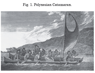
It seems that even in prehistoric times, as evidenced by remains found dating back 3 or 4 millennia, that Austronesian navigators used double hull canoes to colonize Polynesia and settle in the most extensive group of islands in the planet.
The first documented catamaran in modern Europe, designed in 1662 as a member of the William Petty Royal Society was conceived so it could travel faster in shallow waters [7], with less wind and crew than other vessels of the time. Skepticism made it commercially unsuccessful, remaining an unused idea in the West for another 200 years.
During early 2002, the American Navy began building the new generation of vessels to conquer the possible asymmetric “anti-access” threats, such as mines, silent diesel submarines and rapid surface vessels; those known as Littoral Combat Ship LCS.
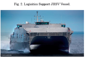
Currently, companies such as Austal and Lockheed Navy, leading the military application vessel design and fabrication sector, mainly for the U.S. Navy, have completely revolutionized these types of vessels, replacing the traditional structure with a revolutionary structure based in multihull solutions, with the purpose of achieving speeds that exceed 45 knots, larger flight decks for helicopters, as well as a considerable increase of internal spaces.
The main priority of the research project that supports this work is the study of the infl uence of hull separation [15] in catamarans to their advance resistance and therefore the power needed on board. For this purpose, each of the resistance components, as well as the interaction between the hulls, will be analyzed.
Research Procedure
Collection and classifi cation of information available from CEHIPAR
CEHIPAR, an Autonomous State Entity, internationally renowned in the area of hydrodynamics, that carries out projects, experiments and research for shipyards, shipping agencies, engineering offi ces, manufacturers and individuals, has been in charge in this case of compiling and classifying all the necessary information regarding bottom data and towing tests.
Among the highlighted suited, the importance and infl uence of hull separation for the resistance component is highlighted [8], as well as a numerical analysis of the individual and combined hulls, necessary activities to know the precision with which these mathematical calculations allow us to discern in each case the advantages of the shapes [5] chosen for a catamaran.
A set of bottoms (2328, 2625, 2688 and 2827) that made part of the catamaran stock of CEHIPAR were used, to which, additionally to the existing sea bearing behavior tests, towing tests restricting their freedom of movement to six degrees have been additionally performed.
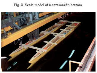
Below are the main characteristics of said models, specifying the corresponding.
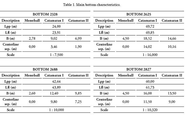
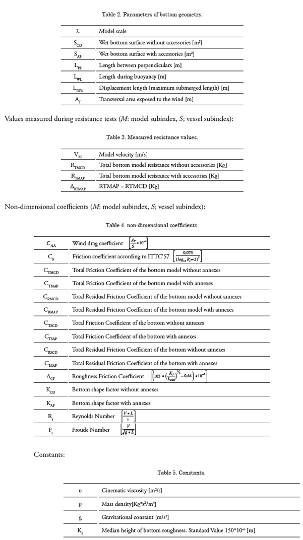
The numerical hydrodynamic studies where done using calculations of viscous fluids for the corresponding project speed and a comparative analysis of the shapes studied was done using procedures developed by CEHIPAR. The main parameters that depend of the bottom’s geometry used to characterize it are found in the following table:
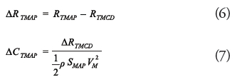
The experimental procedure was performed using the LAMBDA software developed by CEHIPAR; this software allows determining the total model friction coefficient (CTMCD), as well as the residual friction coefficient, (CRMCD), both for bottoms without annexes based on the following equations:
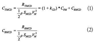
where the shape factor kCD is determined by analyzing the results for Froude’s number between 0.12 and 0.2, whether using the Prohaska method or the minimum method proposed by Hughes, all of them verified with the statistics of similar ships tested at CEHIPAR.
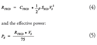
Known that the residual coefficient without annexes (CRMCD) is the same for the model and the ship and there is no scaling effect for the shape factor kCD, the total friction coefficient of the bottom without annexes is determined using the following expressions:
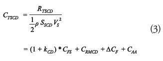
where the friction value without annexes of a real ship is:
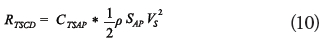
When the bottom test is done with the annexes and there is no corresponding pull test of the bottom without annexes, the extrapolation of the test with annexes is done analogously to that indicated for the bottom without annexes, unless it expressly indicates otherwise:
The value of the increment of the friction coefficient for the real ship is determined using the expression:
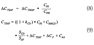
finally obtaining the total friction value for the ship with annexes:
After analyzing and classifying the available information, we began with the market study for these types of vessels, as well as the speed ratio studies, capacity and route distance studies so that they are advantageous regarding monohull vessels, developing a series of steps to generate information for the design object of this report:
1. Definition of the shape parameter ranges for new existing catamarans
2. Developing a design that falls within the mean of the ranges obtained in the previous numeral.
3. Create a list with the bottom parameters that may influence the hydrodynamic characteristics.
4. Develop a systematic series from the design created in 2 that covers the ranges in 1.
5. Calculate the hydrodynamic characteristics of the systematic series using CFD.
6. Choose the best design.
7. Carry out the experimental trials with the bottom obtained in point 2 and the one chosen in point 6.

Database
Table 7 shows the basic characteristics for military application catamarans extracted from a conscientious study and generated for this report.
Development of the Project
Initially there are two types of bottoms for each of the hulls that comprise a catamaran; symmetrical and asymmetrical shapes. In both cases, the inf luence of hull separation on resistance is important. Since there is a possibility of performing a numerical analysis of each hull and of the hulls together, it is necessary to precisely know what these mathematical calculations allow us to determine for each hull and the advantages of the shapes chosen for a catamaran (6).
Study of numerical hydrodynamics through viscous fluid calculation
CFD (12) software are tools based on the use of computers to simulate behavior of systems related to f luid f low, heat transfer and other physical processes. They work by solving the equations that determine the f low of f luids in the region of interest under conditions preestablished for the boundaries of said region. The set of equations that describe these types of physical processes are the Navier-Stokes equations; as it is known, these equations do not have a general analytical solution but can be simplified and numerically solved. They way in which these processes are performed depends on the CFD code used. The most common one, and the one on which CFX is based, is the one known as finite volume technique.
Using this technique, the region of interest is divided into smaller subregions, called control volumes, and the equations are simplified and solved for each control volume interactively. This way, there is an approximation to the value of each variable described in the physical process, at certain points within the defined domain. From these values, the full behavior of the f luid in the entire set can be deduced. On the other hand, the CFD codes can assume certain simplifications of the equations and thus classify them in different ways.
The calculations were made using the CFX 14.5 software developed by ANSYS, since it was a non-linear viscous program. Bottom number 2827 was split, and its main geometrical characteristics are shown in Table 8.
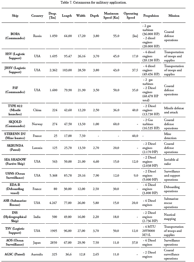
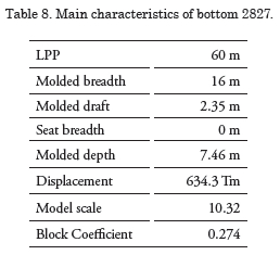
Fig. 4 shows details of the transversal of the sections and contours, as well as the area and buoyancy curves for the selected bottom.
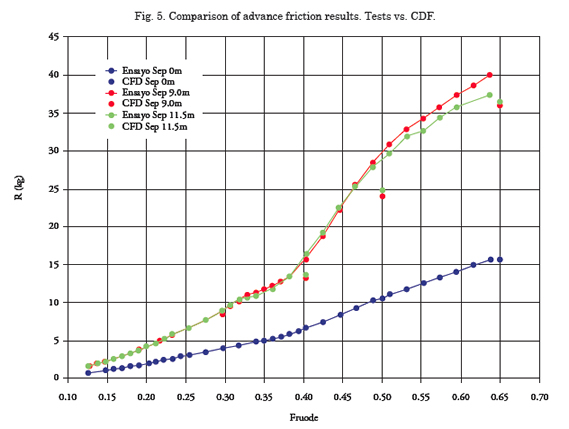
The calculations were done for a monohull configuration and two types of catamaran, with a hull separation of 9 and 11.5 m respectively. In all cases, calculations were done with a naked bottom at scale model, in 4 different speed regimes (between 14 and 30 knots approximately) and under meshing of very similar domain total.
Movement of the bottom has been restricted to its six degrees of freedom. For the case of the monohull (14), there is no point in freeing the ship, while in the case of the catamarans, computational time would have been excessive due to the large number of elements that comprise the mesh, given that the symmetry condition cannot be applied as a consequence of hull interference. Th e results obtained are show in Fig. 5.
Taking into account the results shown in Figure 5, we may deduce that the CFD calculations are valid for defi nition and optimization of monohull bottoms since, as observed, the diff erences with the test values are minimum and acceptable. However, the same cannot be said for the case of catamarans, were the CFD results do not have the required level of precision, always obtaining more optimistic results than those of the tests. Also, it may be observed that there are barely any diff erences between the points obtained for both hull separations studied, which suggests that using CFD it the most adequate option to optimize the distance between them. Th e decrease in quality of the CFD results for catamarans could be due to the incorrect simulation of hull interaction, suggesting the using a fi ner mesh for the separation area could be necessary and maybe a diff erent turbulence model.
Comparative analysis of shapes
Using another application developed by CEHIPAR we may evaluate the area and buoyancy curves of a bottom. In the case herein exposed, being a catamaran, the shapes adopted for each of the hulls was analyzed, without evaluating the suitability of the symmetrical over the asymmetrical hull, as well as the separation.
Th is application, using the Cca parameter indicates the existing directly proportional relation between the area curve and advance resistance (4), so that, the latter will be less as the Cca index decreases. At the same time, it allows, based on an area curve, to obtain the optimized area curve keeping the displacement of the original bottom. Analogously, once the bottom’s buoyancy is studied, and the Ccf index is obtained, the application may assess the convenience of introducing modifications to it by adequate sleeve distribution. The lesser the Ccf index the less resistance to advance of the bottom.
It should be noted that when a modification of a bottom is made in order to obtain the optimized area curve, considerable reductions of viscous resistance could be obtained. In the case of obtaining attractive power efficiencies, these values should be taken carefully, because although the power variation of the Cca and Ccf coefficients is linear, since this application is still in its development phase, there are no guarantees of the linearity up to its origin. Following are some of the most significant results of the tested bottoms.
• BOTTOM 2328 – in this case, a modification of the shoulder of the original area curve resulted in almost a 10% decrease of the viscous resistance of the speed of 21 knots. On the other hand, for the same speed, a modification of the floatation curve allowed to reduce resistance by making waves, over 15%, a significant value due to the large specific weight it has over total resistance.
• BOTTOM 2625 – in this case the first modification of the area curve allowed a reduction of more than 40% of the viscous resistance at a speed of 21 knots; this data generated reservation, making new modifications to the area curve only to the stern area to the master section, the modifications of buoyance barely reduced resistance through wave formation.
• BOTTOM 2668 – it was decided not to introduce shape modifications that were not strictly necessary since they could be associated to changes of the elements of general disposition like the machine room. Due to this, in many cases, simple changes to the area curve of the front area suppose an optimal modification to reduce the total resistance by the same percentage.
• BOTTOM 2827 – in the same way as bottom 2625, a first modification of the area curve with the subsequent reduction of close to 50% of viscous resistance at a speed of 21 knots, with certain reservations, making new modifications of the area curve only in the front area up to the master section.
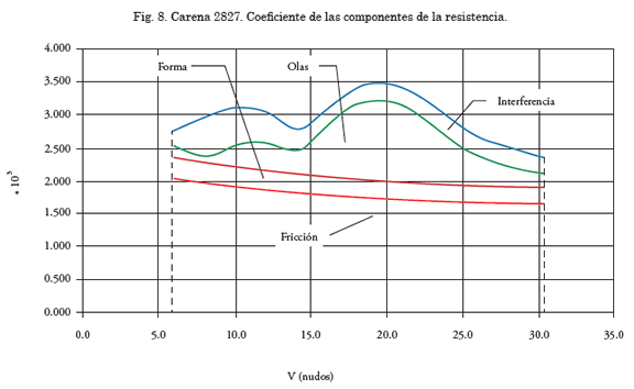
Relative influence of resistance components
For the bottom shape project with optimized resistance behavior and therefore fuel consumption, it is necessary to have the most precise vision of how the resistance influences each of the components, treated separately, as well as together. For catamaran-type ships a detailed knowledge of hull interaction is needed, a study that is not necessary for monohull ships and, with great differences with respect to trimaran ships (3) since for those, 90% of the displacement volume is at the central hull.
Generally, a ships resistance is decomposed in viscous and residual resistant. Viscous resistance is pressure and friction, while residual is mainly resistance from waves that the ship generates while displacing water at a certain speed and by other components such as wave breakers, roughness, viscous-wave interaction, etc. Catamaran-type ships produce a particular phenomenon which is hull interference (1) between the hulls that compose that bottom and creates interference resistance.
Based on the experimental results of the bottoms tested in this investigation, we try to analyze the three components of resistance: viscous, residual and interference. To achieve this three towing tests have been conducted for each catamaran bottom, having firstly tested each of the hulls individually. This test must be performed with the dynamometer with six components since the individual hull does not have its own stability and it is therefore tested in the captive model, that is, the allowed monohull model has not been allowed to take dynamic seats.
The towing tests for catamaran bottoms have been done in the usual way, allowing the model to take the dynamic trim for each speed. The extrapolation of the results obtained from the towing tests has been done according to ITTC’78 indications.
Study of viscous resistance. Determination of the shape factor
As mentioned, viscous resistance is composed of pressure and friction resistance. The viscous resistance coefficient is expressed as:
The k coefficient in the expression of the CV viscous resistance coefficient, assumes the difference of shape between a flat plate and the ship, having different procedures to determine it, but, independent of the method used, its value should be practically the same. The k shape factor is calculated using the Proshaka method, in the way indicated by the ITTC, for individual hull, as well as for catamaran-type bottoms. As commented in this study, calculation of all the towing tests has been done using LAMBDA software developed by CEHIPAR.
• BOTTOM 2328 – results of comparing the total resistant coefficients for the catamaran and monohull with the shape factor calculated using the Prohaska method, as well as using the same shape factor for the catamaran as the one obtained for the monohull, showed that if the shape factor determined in each test were to be used, the catamaran with hull separation of 3.462m would offer less resistance than the one with a theoretical infinite separation between hulls. On the contrary, if the test results are extrapolated using the shape factor of the monohull, the results agree more than expected.
• BOTTOM 2625 – in this case it was observed that when extrapolating the tow test with the shape factor calculated for the catamaran, there could be estimated as valid as those obtained through testing of the monohull, even though considerations of resistance due to wave forming show the opposite. On the contrary, if the test using the monohull shape factor are extrapolated, the results agree more than expected.
• BOTTOM 2688 – in the case of this bottom, no matter the hull separation, it may be proven that using the shape factor of a monohull to extrapolate the catamaran results is justifiable. The power obtained using the monohull shape factor will be between 2 and 3% more conservative than if using its own in each test.
• BOTTOM 2827 – finally, this bottom showed that the results of total resistance coefficient for the catamaran and the monohull with the shape factor calculated using Prohaska’s method, as well as using the catamaran with the same shape factor obtained for the monohull. The values obtained for the total resistance coefficient in extrapolation for the towing test ship, both for its own shape factors as for the monohull’s, do not present any abnormality and the value generally decreases as separation between hulls increases. The power obtained using the monohull shape factor will be approximately between 1 and 2% more conservative than when using its own in each test. In view of the results obtained, it should be accepted as a reasonable practice to adopt the same shape factor for a catamaran as the one obtained from testing a monohull, since the results are slightly more conservative.
Study of resistance due to wave formation
In the same way as in the case of viscous resistance study, to calculate resistance due to wave formation (5) the four bottom models were tested, in the monohull and catamaran situations with two different hull separations (13). Also the extrapolated results of a real ship have been analyzed using the shape coefficients obtained using the Prohaska method for each test, as well as the one from the single hull.
• BOTTOM 2328 – In this case the wave formation coefficient, Cw, corresponding to a larger separation between hulls, is less than that of a single hull. A priori, it would have to be interpreted as the wave trains generated by the catamaran are cancelled, at lease in part of the two hulls. However, using the catamaran for the same shape factor as the monohull, generally coefficient Cw is less than for the monohull than for the two catamaran models tested. The fact that the Cw values decrease as hull separation increases, shows that there is an interference resistance that decreases when separation increases, the limit value being that of the single hull, equivalent to an infinite separation between them.
• BOTTOMS 2625, 2688 y 2827 – for these bottoms, the wave formation coefficient, Cw, for low speeds are less for the catamaran bottom than for the monohull, whatever their separation. Since it was not proven that interference between both wave trains in both hulls can be partially cancelled, it is best to opt for a more conservative extrapolation using in for all cases the monohull shape factor. In the studied cases, the maximum wave formation coefficient, Cw, corresponds to a Froude number of 0.5.
Study of resistance of interference between hulls
The variations of the residual resistance coefficient, δCw , as a function of Froude’s number, Fn , were studied for each of the bottoms and separation between hulls, observing that for the smallest tested catamaran, interference resistance can be cancelled for very high values of Fn when in a planning zone where the resistance value due to wave formation is practically independent of the shapes, as well as observing a considerable influence in it of the separation between hulls.
To the contrary and for the rest of the bottoms, it is observed that for an Fn value of 0.4, interference resistance is practically independent from hull separation. In conclusion, this figure shows the different components of towing resistance, observing the relative importance of each of them so that when a project is developed the order of magnitude expected from shape optimization can be clear.
Results analysis and procedure validation
Application of catamaran-type platforms from the propulsive point of view.
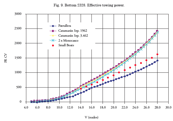
Using software MJ-3A (2), developed during another project of the Spanish Ministry of Defense, to predict towing power without annexes of four patrol ships, of the same length and displacement as each of the four catamarans tested during this study, isolating each of the hulls, as well as with the same separations, comparing the results obtained for all of them. The patrol ship has a very similar propulsive behavior and much better than the catamaran when the catamaran’s behavior is very similar when varying separation between hulls but also in relation to the individual hulls.
The possibility of improving resistance of shapes in this catamaran bottom does not justify the difference with the conventional patrol boat bottom. It is true that due to the small size of the boat, the prediction procedure of MJ-31 could not be especially adequate and the results could be very optimistic.
To prove this point, a power-speed (9) prediction was done for the conventional bottom using the SMALL BOATS program to obtain quick prediction for small high-speed boats than even though it is not un trustworthy as other methods, it does provide enough guidance for certain types of ships, such as yachts.
This new prediction for a conventional ship equivalent to tested catamaran 2328 turns out to be more pessimistic than the initial one and appears to confirm that this ship would have a better propulsive behavior with conventional bottom than with a catamaran bottom. From the comparison between the catamaran bottom and the conventional bottom for bottom 2668 we may conclude that the propulsive qualities of the catamaran bottom are better than those estimated for the monohull bottom of the same length and displacement even If the propulsive differences are between 5% and 15%.
Considering all this, we consider that the catamaran bottom is sufficiently optimized, with a margin for improvement in viscous resistance as well as wave formation resistance since the conventional shape bottoms are considered analogous to the patrol boats used as ships to perform the high-speed prediction, as a consequence of the comparison between the two types of platforms that in this case would be considered trustworthy.
From the comparison between the catamaran and the conventional bottoms for bottom 2827 we conclude that its propulsive qualities are worse than those estimated for the monohull bottom of the same length and displacement up to speeds of 15 knots, with a reduction of effective power between 1 and 30%. For speeds exceeding 15 knots there is an inversion of behaviors of catamaran bottoms, even though the propulsive improvement is minimal with barely 2% difference.
For the case of the catamaran, as well as for the conventional bottom, there could be an improvement to towing resistance projecting sufficiently optimized shapes.
Lastly, there is a comparison between the results obtained with bottom 2625, the longest tested catamaran. For this case, the conventional bottom shows less resistance than the catamaran bottom at all tested speeds. There could be a strong improvement to towing resistance modifying the shapes to obtain an optimized curve area.
From the propulsive point of view, and considering the results obtained from the different tests, the possibility to adopt catamaran-type shapes for the range of 40 to 70 m lengths should be studied. We should not forget other factors when selecting the type of ship, such as the positive aspects of the catamaran vessel regarding ampleness of decks with the versatility that it confers the ship, as well as the negative aspects such as the need for a more sophisticated control system to achieve better sea behavior (10).
Estimation of advance resistance for catamarantype ships
With the data obtained in this investigation is is not possible to create a generalized prediction procedure for all catamarans, but only to provide some indications that may give an approximate idea of the resistance values for a catamaran within the value range of the ships studied herein. The election of a catamaran geometry needs to first optimize each of the monohulls, symmetrical or asymmetrical, depending on the ship’s mission and the speed range. In the case of symmetrical monohulls, the project can use the same optimization criteria as for single hull ships.
The shapes of the monohull are valued using systematic variation of the different parameters that govern them and testing the corresponding models. Calculation of the initial shape factor, k, allows knowing friction resistance. As far as the wave component the Froude number is calculated, Fn, for which resistance is maximum and the approximate Cw (11) values for different Fn as a function of the Lpp / Δ1/3 parameter. With a similar precision the values of total resistance may be known, using for that the R/ Δ correlation formulas for all bottoms in the data base as a function of Lpp/ Δ1/3 .The value of R2 is larger than 0.85 for Fn between 0.5 and 0.6.
Conclusions
This article has tried to summarize the work done throughout an investigation financed by Spanish Ministry of Defense through the General Planning, Technology and Innovation subdirectorate, highlighting the interest in furthering the hydrodynamic knowledge on multihull ships, as is the case of catamarans. With the data obtained, indications and recommendations that could give an approximate idea of the resistance values for a catamaran where intended to be given, within the range of values of the ships studied herein.
This work intends to make an emphasis that at the time of designing the geometry of a catamaran there should be an optimization of each of the monohull that conform it, were the shapes have to be assessed using systematic variation of the different parameters that govern them, and testing of the corresponding values. This way, optimization of area curve, as well as buoyancy of the bottom maintaining the original displacements, have notable reduction associated to advance resistance.
Finally pointing out that incorporation of multihull ships to the naval industry has gone across borders, and that these types of constructions are becoming a current building trend for different navies as opposed to monohull structures, always based on the needs and typologies for which these units are used.
References
ALAEZ, J. (1991). Catamaranes de alta velocidad. Publicación 130, Canal de Experiencias Hidrodinámicas de El Pardo, Madrid, España.
GARCÍA, A y BOBO, M. (1999). Programa MJ-3A. Predicción de potencia-velocidad para buques rápidos. Canal de Experiencias Hidrodinámicas de El Pardo, Madrid, España.
GARCÍA, A. y RIOLA, J. (2013). Proyecto hidrodinámico de un buque de escolta oceánico tipo trimarán: Dimensionamiento, diseño, estudio numérico y experimentación. Congreso DESEi+d 2013, Madrid, España.
LEVI, C. y SALHUA, C. (2007). Modificación del sistema de propulsión de un catamarán de pasajeros. XX Congreso panamericano de ingeniería naval COPINAVAL, Sao Paulo, Brasil.
MACFARLANE, G. y DAIRE, N. (2011). The influence of catamaran hull form on added resistance in head seas. 11th International Conference on Fast sea transportation, Hawai, USA.
MICHEL, J. (1898). The wave resistance of a ship. Philosophical magazine, 45, pp 106-123.
MILLWARD, A. (1992). The effect of hull separation and restricted water depth on catamaran resistance. Trans. R.I.N.A, 134.
MORAES, H., VASCONCELLOS, J. y LATORRE, R. G. (2004). Wave resistance for high-speed catamarans, Ocean Engineering, 31, 2253-2282.
PHAM, X., KANTIMAHANTHI, K. y SAHOO, P.K. (2001). Wave resistance prediction of hard-chine catamarans through regression analysis. 2nd International Euro Conference on High Performance Marine Vehicles, Hamburgo, Alemania.
RIOLA, J., PÉREZ, R. y DÍAZ, J. (2013). Análisis del comportamiento en la mar de buques de guerra multicasco. 52º Congreso de Ingeniería Naval e Industria Marítima, Madrid, España.
SAHOO, P., SALAS, M. y SCHWETZ, A. (2007). Practical evaluation of resistance of high-speed catamaran hull form. Ships and offshore structures, 2, pp 307-324.
SALAS, M., SAHOO P. y LUCO, R. (2008). Avances en la estimación de la Resistencia de Catamaranes. SHIP Science and technology, 2, (3), pp 39-46.
SARLES, C., GELLES, B. y MALARKEY, A. (2011). An investigation into the effect of section shape on the interference resistance of catamarans. 11th International Conference on Fast sea transportation, Hawai, USA.
THOMAS, G., TOMIC, P. y TUITE, A. (2006). High-Speed catamaran or monohull? How do you choose? 5th Conference on high performance marine vehicles (HIPER´06), Lancester, Australia.
ZAGHI, S., BROGLIA, R. y DI MASCIO, A. (2010). Experimental and numerical investigations on Fast Catamarans Interferente Effects. 9th International Conference Hydrodinamics.