Structural Analysis of an Aluminum Multihull
Análisis estructural de un Multicasco de aluminio
David Fuentes1
Marcos Salas2
Gonzalo Tampier3
Claudio Troncoso4
Abstract
Structural analysis of a multihull is relatively complex since the connecting structure introduces additional stress than those typical of a monohull. The aluminum trimaran presented in this work was designed within the framework of the research project “Conceptual Design of a High-performance Vessel for Passenger Transport in Chile’s Austral Zone”. The trimaran was structurally measured using the regulations of classification societies Germanischer Lloyd, Det Norske Veritas y Lloyd´s Register. For the scantlings obtained with each regulation a Finite Element Model was created and the structural analysis for the slamming and splitting moment events was made. The results were analyzed and the stress concentration zones were determined to compare them with admissible stresses and conclude whether the structural sizing adequately and safely responds to the design stresses.
Key words: Multihull, structural analysis, finite elements
Resumen
El análisis estructural de un multicasco es relativamente complejo debido a que la estructura de unión entre los cascos introduce esfuerzos adicionales a los típicos de un monocasco. El trimarán de aluminio presentado en este trabajo fue diseñado en el marco del proyecto de investigación “Diseño Conceptual de Embarcación de Alto Desempeño para el Transporte de Pasajeros en la Zona Austral de Chile”. El trimarán se dimensionó estructuralmente usando los reglamentos de las sociedades de clasificación Germanischer Lloyd, Det Norske Veritas y Lloyd´s Register. Para el escantillonado obtenido con cada reglamento se creó un Modelo de Elementos Finitos y el análisis estructural se llevó a cabo para los eventos de slamming y splitting moment. Se analizaron los resultados y se determinaron las zonas de concentración de esfuerzos para compararlos con los esfuerzos admisibles y concluir si el dimensionamiento estructural responde en forma adecuada y segura a las cargas de diseño.
Palabras claves: Multicasco, análisis estructural, elementos finitos.
Date Received: September 30th, 2014 - Fecha de recepción: 30 de noviembre de 2014
Date Accepted: January 8th, 2015 - Fecha de aceptación: 8 de enero de 2015
________________________
1Diseñador - Gerencia de Diseño e Ingeniería. COTECMAR. Colombia
2Profesor Universidad Austral de Chile. Valdivia, Chile.
3Profesor Universidad Austral de Chile. Valdivia, Chile.
4Profesor Universidad Austral de Chile. Valdivia, Chile.
............................................................................................................................................................
Introduction
Structural analysis using the Finite Elements Method is a tool for structural design of vessels, that allows verifying if the structural sizing complies with the established acceptance criteria and to determine points of stress concentration, according to the admissible loads hypothesis in the analysis.
The purpose of this work is to analyze the structural response of a multihull vessel, designed in aluminum, by constructing a Finite Elements Tridimensional Model, for each structural sizing calculated using the regulations of the classification houses “Germanischer Lloyd” (GL), “Det Norske Veritas” (DNV) y “Lloyd´s Register” (LR). The results obtained for each of the models are compared with the established acceptance criteria for each classifiers. Recently, using the finite elements method, Morris (1991) and Ojeda et al. (2004) performed different structural analyses to multihull vessels were they identified the stresses and deformations of the structure; using the same method, Paik and Hughes (2006) and Blanchard and Chunhua (2007) analyzed the different cargo conditions established by different classification houses were they highlight the Slamming load in the Crest Landing and Hollow Landing moments and the Splitting Moment.
Vessel Characteristics
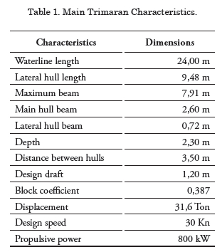
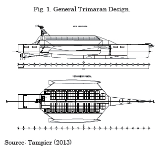
The vessel being analyzed is a Wave Piercing multihull trimaran defined by Tampier (2013) as the “design that offers the best set of good sea keeping capacities, transversal stability, ease of distribution and the least power requirement”. The main characteristics of this ship are shown in Table 1., the same way presented in the general assembly of the ship in Fig. 1.
Cargo Conditions
According to Cheng and Mayoss (2007) for small and medium vessels, the main criteria governing structural design are local stresses. Theses types of stresses are produced by those events that make a vessel’s structure be in the most unfavorable condition during the navigation period. However, considering that the vessel being analyzed is multihull some global events must also be evaluated, as follows:
Slamming event of the hull
This occurs when the vessel suffers a severe impact against the water as a result of a pitch and heave movement at advancing speed. This is a strong and intense impact that generates large hull pressures; this event is one of the most common causes for structural damage of the hull.
GL classification houses establishes that slamming pressure acts between 0,5L y 0,8L; and calculates it using the following equations:
![]()
Where:
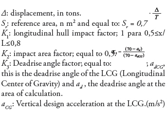
The DNV classification houses analyzes the slamming event experienced by a vessel during navigation during two moments; the moment of crest landing (CL) (Fig.2), happens when the vessel lands on the crest of the wave, this pressure acts upon the reference area placing this area at the LCG. The Hollow landing (HL) moment occurs when the vessel falls upon the hollow of the wave (Fig. 3); likewise, this pressure acts upon the reference area which is divided between the bow and the stern in this case. The mentioned reference area (AR) is found using equation (2).
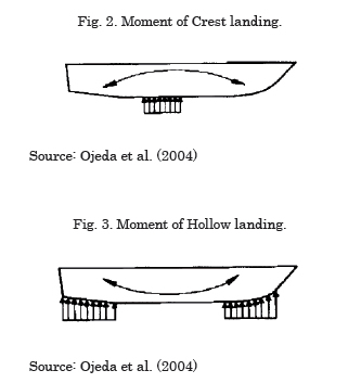
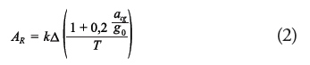
Where
AR: reference area (m2)
k = 0,7
Δ: displacement in tons
T: design breadth (m)
g0: acceleration of gravity (m/s2)
acg: vertical design acceleration acting upon the
center of gravity (m/s2)
The slamming pressure that acts upon the previously mentioned reference areas is found using equation (3):
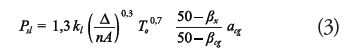
where:
Psl: slamming pressure on the hull (kN/m2)
Kl: longitudinal distribution factor
n: number of hulls
A: design area for the considered element (m2)
To: breadth in L/2 (m)
Δ: displacement (Ton)
βx : deadrise angle of the transversal section to
consider (minimum 10° maximum 30°)
βcg: deadrise angle at the center of gravity (minimum 10° maximum 30°)
acg: vertical acceleration of design (m/s2)
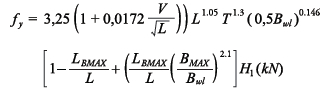
The LR classification houses establishes that the slamming pressure is exerted by the hull between 0.8L and L of the main hull and stabilizers is given by equation (4):
![]()
Where:
IPbi: slamming pressure at the hull (kN/m2)
fbi: impact factor at the hull, equal to 0,18
Tx: design breadth (m)
Vsp: service speed or 2/3 of maximum speed. (knots)
Slamming event at the connection deck
This event occurs due to pitch and heave at the vessel´s advance speed, which produces a strong impact on the water against the connection deck of the lateral hulls of the main hull. This phenomenon is magnified by the funneling effect produced between the lateral and main hulls.
The GL classification houses established that slamming pressure on the connection deck will occur when the distance between the bottom of this deck and the design water line is less than zwd = 0,05L ; likewise this pressure acts between 0,8L and L. (Equation 5)
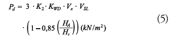
where:
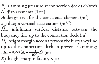
The DNV classifier house establishes that the slamming pressure on the connection deck is found using equation (6)
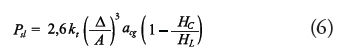
where:
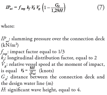
For the LR classification houses the slamming pressure upon the connection deck is exerted between 0.8L and L of the mentioned structure and is given by equation (7):
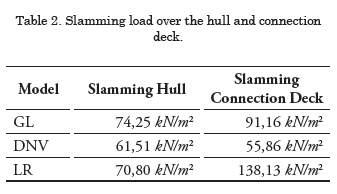
Also, for the model to adequately represent reality, the hydrostatic pressure exerted by the sea over the hull of the vessel was considered. The effects of inertia forces due to vertical acceleration were also taken into consideration. Table 2 shows the pressure according to each classification houses. It should be mentioned that slamming pressure for the DNV classification houses is less because of design acceleration, calculated with this regulation, is less than the one calculated with other regulations, as well as the maximum admissible stress, which is less with this regulation.
Splitting moment or lateral hull separation moment
This event occurs when due to the force of the waves, the lateral hulls are pressured to move closer or further away from the main hull, giving rise to structural tensions on the connection deck. To simulate this event, the classification houses establish that a force must be applied that generates the value of the transversal flexion moment, which can also be generated applying pressure to the lateral hulls that generate the calculated moment.
The GL classification houses establishes that the transversal flexion moment is found using equation (8):
![]()
where:
Mbt: moment of transversal flexion (kNm)
b: transversal distance, in meters, between the central lines of both hulls
g: acceleration of gravity, 9,81 m/s2.
acg: vertical design acceleration at the LCG. (m/s2)
The DNV classification houses establishes that the transversal flexion moment for a multihull is found using equation (9):
![]()
where
Ms: moment of transversal flexion (kNm)
MS0: moment of transversal flexion in calm waters,
MS0 = 4,91Δ(yb - 0,4B0,4)(kNm).
Yb: distance between the central line of the central hull to the lateral hull (m)
B: Maximum beam(m)
fy: separation force at the submerged area
H1: significant wave height (m)
Bwl: maximum beam at the water line (m)
BMAX: maximum beam (m)
LBMAX: length at maximum beam (m)
z: distance between the base line of the connection
deck (m)
T: draft (m)
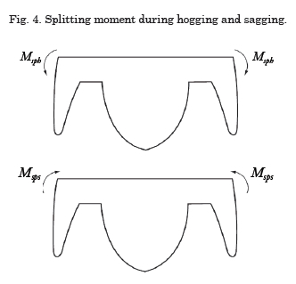
The LR classification house establishes that for a trimaran type vessel, analyzing two moments of hull separation, during hogging (Msph) which is when the lateral hulls tend to come together with the central hull due to wave action and sagging (Msps) that is when the lateral hulls tend to drift away form the main one; they are found using the following equations; Fig. 4 shows an illustration of both moments.
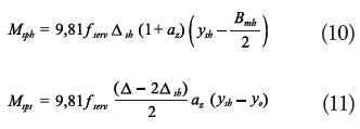
where
Msph: moment of separation during hogging (kNm)
Msps: moment of separation during sagging (kNm)
Δsh : displacement of lateral hull (Ton)
ysh : distance between the center line of the central hull and the lateral hull (m)
yo : distance between the center line of the main hull and the connection between the lateral hull and the connection deck (m)
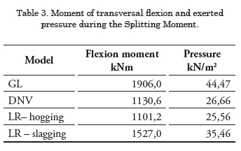
Table 3 shows the results obtained for the moment of transversal flexion and the pressure exerted over each model.
Other boundary conditions
As a boundary condition, the inertia relief condition was established, which acts leaving a model of the free body considering the inertia of the movements that may be produced on the model and allowing the applied loads to act over it without the restriction generated by other types of restrictions. This tool calculates any load unbalance and applies inertia forces along the model with the purpose of obtaining equilibrium, Morris (1991).
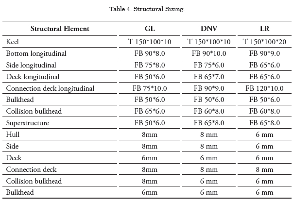
Scantling of the Vessel
Scantling of the vessel was done using the classification regulations of “Germanischer Lloyd”, “Det Norske Veritas” and “Lloyd´s Register”. Each of the scantlings is specified on Table 4.
Finite Elements Model
Using the Rhinoceros software, a 3D model of the hull was constructed and the scantling structure calculated with each classification house, since although the geometry of the hull is the same, there are difference both in the planking thickness as well as in the size of the reinforcements. Then, each of the 3D models was imported into the ANSYS structural analysis software. For the material, the mechanical properties of 5083 aluminums were assigned, with a density of 2770 Kg/m3, elasticity module 7,1x10¹⁰ Pa and Poisson coefficient 0,33.
Meshing
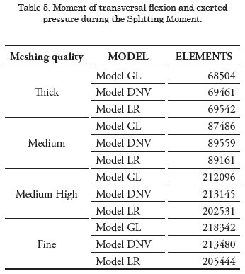
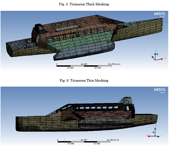
Four types of meshing were done in order to compare the results obtained with each model as far as thee percentage and change trends of the results, and thus optimizing the use of the existing computational resources and verifying the meshing sensibility. Initially a thick meshing is made without advanced refinement functions, quick element transition and medium softness. The next meshing corresponds to a medium quality meshing, without advanced refinement function, slow transition between the elements and high softness. After this, there is a medium high level meshing, with advanced refinement functions, increasing the amount of elements found in proximity with other parts and/or contact regions, medium relevance level and high softness. Finally, there is a fine meshing with advance refinement meshing, increasing the amount of elements found in proximity with other parts and/or regions of contact, increasing the amount of elements in the curvatures, medium level of relevance and high softness. The elements used are “SHELL 181”, in each refinement it was verified that the elements complied with the aspect relation necessary for the element to continue behaving as a “Shell” element. Table 5 shows the amount of elements used in each meshing by the model, and Figs. 5 and 6 show the trimaran with thick meshing and fine meshing, respectively.
Structural Analysis
The structural analysis of the models evaluated the slamming and splitting moment loads, thus comparing the results obtained with different meshing and finally verifying if the results obtained comply with the minimum acceptance criteria established by each classification house.
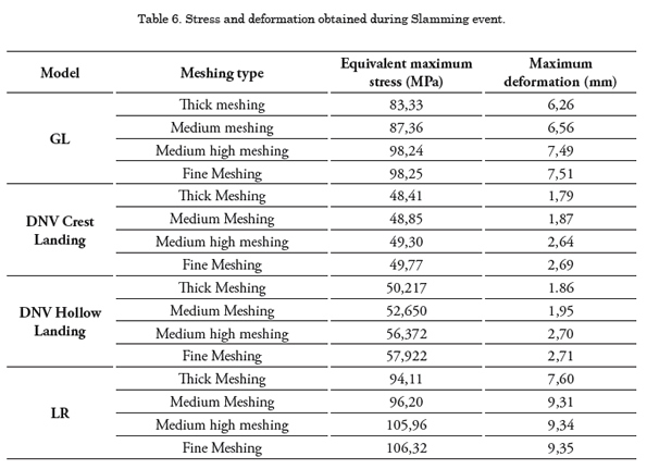
Slamming event simulation results
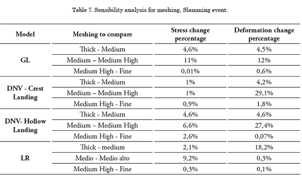
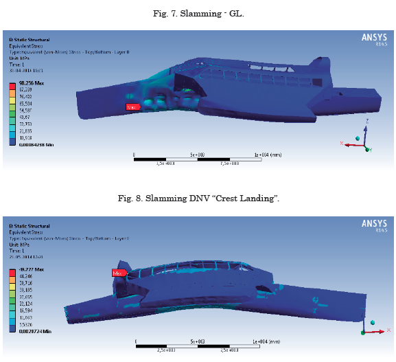
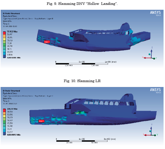
When simulating the slamming event for each constructed model and taking into account the disposition of the loads explained in the previous section, the results shown in Table 6 are obtained. In order to verify the mesh sensibility and define the meshing that best represents the structural response of the vessel upon the action of different loads, and proceeded to compare the results obtained for each meshing. It was observed that the stress and deformation increase as the meshing becomes finer, for the scantling model with the GL classification house, the between the thicker meshing and finer meshing the maximum stress increased by 15.1% and deformation increased 16.6%. The model of the DNV classification house for crest landing the difference between the stress with thick meshing and the stress with fine meshing is 2.73% while the deformation difference for the same meshing is 33.4%; for the hollow landing moment, the stress increase between the thicker meshing and the finer meshing is 13.3% and deformation increased 31.4%. For the scantling model with the LR classification house, maximum stress between the thicker and finer meshing increased by 11.48% and deformation increased 18.63%. Table 7 presents a comparison between the percentage of change as the quality of the meshing improves, the analysis performed to the results presented in this table may conclude that the model that best represents the structural response of the vessel is the medium-high meshing, taking into account that the percentage of change with this meshing and the finer meshing is less than 5% in the models analyzed in each classification house, however when having the necessary computational resources we decided to use the fine meshing as base meshing to compare the results obtained for the finer meshing, with the acceptance criteria issued by each classification house. Figs. 7 to 10 show the results obtained for Fine Meshing.
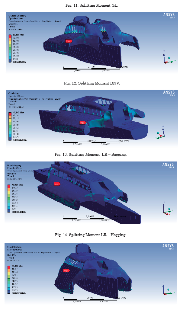
Simulation Results Splitting Moment event
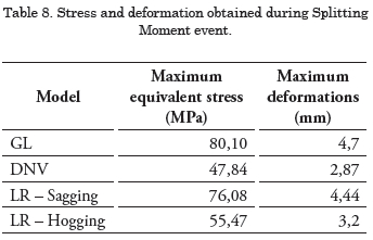
For the simulation of the splitting moment event for each model built, the dispositions of the loads explained in the previous section were used and the results presented in Table 8 were obtained.
Between Figs. 11 and 14 the results obtained for Fine Meshing are shown.
Acceptance Criteria
Acceptance criteria for GL classification house
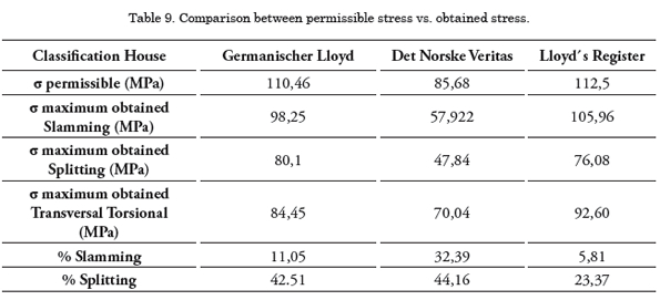
For vessels built on aluminum and designed using GL regulations, the maximum equivalent stress must not exceed the permissible stress σ ≤ 110,46MPa. When comparing the results obtained for the sized model with this classification house with the acceptance criteria, the maximum equivalent stress for the Slamming event g (98,25 MPa) and the Splitting moment (80,1 MPa) event is less than the maximum permissible event.
Acceptance criteria for DNV classification house
The DNV classification house established the acceptance criteria for the equivalent stress obtained in each simulation must be less than σe ≤ 85,68 MPa; when comparing the results obtained with the acceptance criteria, the maximum equivalent stress for the slamming event (57,92 MPa) and the splitting moment event (47,84 MPa) is less than the maximum permissible stress.
Acceptance criteria for LR classification house
The acceptance criteria for this classification house says that the equivalent Von Mises stress obtained for the vessel during each simulation, must be less than σvm ≤ 112,5 MPa ; comparing the results obtained for each sized model with this classification house with the acceptance criteria, it is observed that for the maximum equivalent stress obtained for the Slamming event (106,32 MPa) and for the Splitting moment event (76,87 MPa) is less than the maximum permissible effort.
Analysis of Results
Analyzing the results obtained and making a comparison with the acceptance criteria the maximum equivalent stress for the vessel during the slamming event is between 5% and 32% below the acceptance criteria and for the Splitting Moment event between 23% and 44%, below the acceptance criteria as shown on Table 9.
These results show that when sizing a vessel using the regulations of a classification house ensures that subjecting the structure of the vessel to different events or load conditions, they do not exceed the permissible stresses for each classification house.
Also, when comparing the stresses obtained with fluency of Aluminum 5083 under the welding conditions described by Paik and Hughes (2006), the margin of safety is broader.
Conclusions
The structural analysis of the initial model showed that performing the scantling with the classification house, the maximum obtained stress is below the admissible stress for each classification house between 5% and 32%, depending on the house used, which allows for a relative safety margin in the material.
The finite elements method allows not only to verify not to exceed admissible stresses, but can also identify high stress efforts, which may be diminished with the adequate structural optimization processes, modifying the structural design geometry for example, and that not necessarily can increase scantling in general.
Although the analyzed vessel was a minor vessel, its multihull configuration is affected by different loads than those of the monohull. For this reason, for an exhaustive structural analysis not only the most unfavorable condition must be taken into account, in this case the slamming pressure, but also other conditions that request the structure in a different way must be assessed as well as possible stress combinations due to loads acting simultaneously.
References
ANSYS, Teoría de Referencia Ansys, Version 14.5, Canonsburg: Ansys, Inc., 2011.
BLANCHARD T. Y CHUNHUA, G.; «Rules for the Classification of Trimarans» Naval Engineers Journal, vol. 44, pp. 1 -50, 2007.
CHENG F. Y MAYOSS, C.; The development of Trimaran rules, London: Lloyd´s Register, 2007.
DET NORSKE VERITAS AS, Rules for classification of high speed, light craft and naval surface craft, Oslo: Det Norske Veritas, 2012.
GERMANISCHER LLOYD, Rules for Classification and construction, High Speed Craft., Hamburg: Germanischer Lloyd, 2002.
LLOYD´S REGISTER, Rules and Regulations for the classification of Trimarans Rules, London: Lloyd´s Register, 2006.
MORRIS, J.; «A three dimensional structural analysis of a large wave piercing catamaran design,» High speed marine transportation IMAS 91, pp. 89 - 102, 1991.
OJEDA, R.; GANGADHARA, B.; Y SALAS, M.;«Finite element investigation on the static response of a composite catamaran under slamming loads,» Ocean Engineering, vol. 31, pp. 901 -929, 2004.
PAIK, J. Y HUGHES, O.; «Ultimate limit state design technology for aluminium multi - hull ship strcture,» SNAME Transactions , vol. 113, pp. 270 - 305, 2006.
TAMPIER, G.; Informe Final Proyecto Perfil I+D Aplicada CORFO 13IDL1-18236., Valdivia, 2013.