Development of Fire Fighting & Damage Control automation that enables future crew reduction
Desarrollo de automatización de control de daños y contraincendios que permite la futura reducción de la tripulación
Rinze Geertsma1
Nine Badon Ghijben2
Erik Middeldorp3
Robin de Ruiter4
Abstract
The Holland-class Patrol Vessels of the Royal Netherlands Navy has been designed to conduct world-wide operations with a low level of violence. Minimization of the exploitation costs has been translated in a frigate size vessel design to be manned by a crew of 50. In particular, the support of Battle Damage Repair required serious development as today’s solutions are based upon having a much larger crew. Adoption of modern fire-fighting techniques such as ship-wide deployment of automated water-mist systems and extensive use of center-fed hose reels appeared to be essential steps to cope with lower manning levels. However, that is not enough as there are other internal battle aspects that (today) require significant manpower such as information gathering to obtain the desired situational awareness of the current state of the damage, and complex engineering tasks to mitigate the damages and the management of the necessary resources. For this reason, this paper discusses the approach and development of four (4) platform management system Damage Surveillance and Control (DSAC) applications as an example how future internal battles can be supported to achieve a higher quality (less human errors) of battle damage control, by means of a better situational awareness and a significant reduction of the workload during Battle Damage Repair.
Key words: Battle Damage Repair, Damage Surveillance & Control (DSAC), Fire Fighting & Damage Control (FFDC).
Resumen
Los buques patrulleros holandeses de la marina de los Países Bajos han sido diseñados para conducir operaciones a nivel mundial con un bajo nivel de violencia. Minimización de la explotación de los costos ha sido llevada al tamaño de las fragatas, las cuales son diseñadas para llevar una tripulación de 50 personas. En particular, el apoyo a la reparación de daños en batalla requiere un importante desarrollo dado que las soluciones actuales son con base en mantener un mayor número de tripulación. La adopción de técnicas contraincendios modernas tales como la implementación en la toda la embarcación de sistemas de agua nebulizada de manera automática y el uso extensivo de carretes de mangueras centro-alimentadas, parecen ser pasos esenciales para enfrentar bajos niveles de dotación. Sin embargo, esto no es suficiente mientras que se encuentren otros aspectos internos de batalla un significante esfuerzo de recurso humano, entre los que se destaca la consolidación de la información para obtener la situación actual de los daños ocurridos, así como las complejas tareas de ingeniería para mitigar los daños y la gestión de los recursos. Por esta razón, éste estudio discute el alcance, desarrollo y aplicaciones de cuatro (04) sistemas de gestión de la plataforma para vigilancia y control de daños (DSAC), tomando como ejemplo como futuras batallas pueden ser apoyadas para alcanzar una mayor calidad (disminución de errores humanos) de control de daños, por medio de un mejor conocimiento de la situación y una reducción significativa de la carga laboral durante la reparación de daños en batalla.
Palabras claves: Reparación daños en batalla, Vigilancia y control de daños, contraincendios y control de daños
Date Received: November 15th, 2014 - Fecha de recepción: 15 de noviembre de 2014
Date Accepted: March 2nd, 2015 - Fecha de aceptación: 2 de marzo de 2015
________________________
1Responsible for engineering advice on the new Platform Management System of Joint Support Ship (JSS)
2Senior system engineer platform automation and integration in the Defence Materiel Organization.
3Senior Automation Architect within the Automation Competence Centre of Imtech Marine & Offshore and is responsible for Platform Systems
Solutions such as IPMS and FFDC.
4Is working for Imtech as naval sales manager. He was, amongst others, responsible proposal manager for the upgrade of the IPMS for the M-Class frigates and investigated ‘Task Oriented Design of Integrated Platform Management Systems’, together with the RNLN and Marine Technik Germany GmbH
............................................................................................................................................................
Introduction
Integrated Platform Management Systems
Contemporary Integrated Platform Management Systems (IPMS) provide the promise of reduced manning and increased operational capabilities. However, in the design of modern Human Machine or Graphical User Interface (HMI, GUI) human factors are frequently underrepresented.
Common HMI is based on a representation of the platform installations with simplified process and instrumentation diagrams (P&ID) and corresponding alarm & event handling (Alarm Table). These so called 'mimics' only contains a limited 'functional' representation of the arrangement of components in a specific platform system. Within a mimic, components are represented by a symbol, with dynamic fields for values and control items. Interaction with other systems normally is limited to conditional relations (inhibits) which are programmed in the core of the software.
To be able to safeguard the ship, the operator has to have a profound overview, or situational awareness of the complete system and interaction with other platform components and systems (propagation of failures). Although the amount of I/O steadily increases, not all devices of each system are equipped with sensors and actuators and available I/O data usually is not correlated to provide with a comprehensive situational overview of the platform systems. For operators of IPMS systems, this means that a lot of knowledge and experience is necessary to operate the entire platform from the IPMS, which results in high cognitive loads, especially in case of failure or damage.
Another universal trend is that the system complexity of equipment is growing continuously and a growing number of platform installations are equipped with own 'automation' or CPU's with many I/O and Build In Test (BIT). Frequently, this diagnostic data is directly distributed through the network which causes overflow for operators and hardware. A high automation and integration level is required to support reduced manning and maximize the diagnostic support functions of the IPMS.
As IPMS systems become increasingly complex, negligence of human factors will automatically lead to systems that are more difficult to use, more problematic for training and less effective. In addition, knowledge of the system will decrease rapidly and the operators will adapt with regard to the system deficiency with 'workarounds'.
Future IPMS require Human Machine Interfaces (HMI) for IPMS must assist the users optimally, with information at the right time at the right place required to operate, manage and maintain the technical installations, and in different States of Readiness. In such a task oriented IPMS, processing and visualization information needs to be adapted to tasks, roles and events, i.e. the information shall be matched to given functions or personnel levels (manager, operator, maintainer) of the platform system.
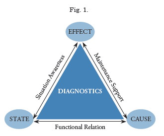
The level of integration and automation of individual components has a direct influence on the allocation of (maintenance) functions or tasks that can be performed by humans, hardware or software. According to RNLN, the diagnostic support function of the (integral) Platform Management System can be divided into three basic elements, namely:
• 'State Function', or availability of hardware and software components of the system or functional chain;
• 'Effect Function' which relates to disturbances of capabilities in the functional chain;
• 'Cause Function’ for fault location and maintenance support.
This model is now being applied throughout all of RNLN new building and modernization projects and as a result, a more structured approach towards Human Factors and allocation of tasks to automated systems to reduce the workload and, subsequently, the size of the crew.
This is reflected in the approach of the (development of) automation systems for the Holland-class patrol vessels, particularly the Damage Surveillance and Control systems.
Holland Class PV Concept
In the operational concept of the newly build Patrol Vessels for the Royal Netherlands Navy (RNLN), the objective was to realize an unmanned Ship’s Control centre. In the “Progamma van eisen voor het realiseren van een onbemande Technische Central”, RNLN focused on the functions and tasks of the Automation System and appointing those to designated personnel, including authorizations, inhibits and individual man machine interfaces, such as workstations, mobile devices and communication equipment. This resulted in an advanced IPMS system with Flexible Function Allocation, which supports the crew in the operation (control and monitoring) of the platform systems.
Apart from the reduction of the workload during normal operation of the vessel, much emphasis was laid on the Damage Control Tasks, as historically these have a significant influence on the size of the complement not only for the marine engineering department, but also for the weapons and operational departments. Therefore, the main potential and resulting measures to reduce the (engineering) crew were considered two-fold, first to have an unmanned ship’s control center and secondly to have a combined Command Bridge to direct all operations, including Battle Damage Repair. In addition, several automated fire-fighting systems were installed including a high pressure water mist system for machinery spaces and cabins. To determine how Battle Damage Repair management can be improved and supported using automation, and reduce the total complement, a workload analysis including task allocation was performed.
Theoretical Framework: Workload Analysis
Platform management processes particularly focus on operational capabilities while maintaining the safety of systems and crew. Even under normal operational circumstances this is a challenge for the complement of the ‘Holland’ Class Patrol vessels, but becomes paramount in the event of damage. In this case, the primary goal of the management is to create an overall Situation Awareness for correct decision making. This requires a very complex and layered organization and information model that is able to identify, assess and respond to a great variety of events that can occur. For the technical departments, platform management is directed towards the availability of operational capabilities, decomposed to the correct functioning of operators, maintainers, installations and components.
As a result, the technical departments’ main objective is to provide with diagnostic information, i.e. Situational Awareness as well as operation and maintenance of the subordinate systems and installations. This requires in-depth knowledge of the platform systems and their interrelationships and implies that for all levels within the organization the goals (Command Aim) are known and projected on solving complex system problems.
Human Centered Approach
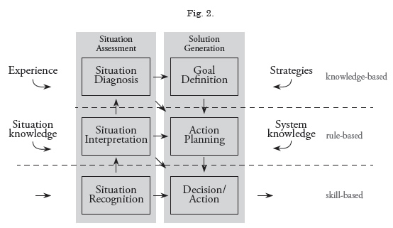
According to Rasmussen (5) information processing and decision making on board ships can be assigned based on three different levels (shown in the model below):
• Skill-based (or natural) behavior: predetermined signals are physically and automatically interrelated directly with one or more actions to be performed (nature/ common sense).
• Rule-based (or procedural) behavior: situations are interpreted according to general rules for a certain situation.
• Knowledge-based behavior: if there are no rules present, in e.g. a new situation, one will assess the situation by calling experiences and by building correlations between information triggers.
In the development of IPMS systems, like Imtech, most manufacturers only apply technical frameworks to make sure that the technical requirements will be met. As a result, humanrelated requirements are not involved at all. Absence of knowledge on intended operational processes on board is the main cause why the actual users are not happy with the delivered system, complaining that their tasks are not supported by the actual system.
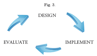
For the development of the Battle Damage Repair support functions, a more Human Centered Approach was chosen to specify requirements and develop solutions for the DSAC support applications. Th e chosen approach actually fi ts the standard DIN EN ISO 13407 standard on human-centered design processes for interactive systems. Th e method calls can be summarized with the following model, and implies the following realization:
• Investigative research on intended workfl ow or work Description (tasks, decisions etc)
• Visualize the intended context of users and systems (objects, people, locations, communication and relations with other objects etc)
• Discussions with the intended users to document equirements and expectations.
• Evaluate interim ideas and concepts of the to be delivered system by any means of prototyping (e.g. screen shots, diagrams, material prototypes etc) and adapt the solution according to the results of these evaluations
• Evaluate the delivered system once it has been in operation for a number of months.
In 2010, the Royal Netherlands Navy and Imtech Marine & Off shore formed a Fire Fighting and Damage Control (FFDC) workgroup to address this problem and aforementioned approach to develop the necessary applications to support Battle Damage Repair.
For the initial contract, a number of requirements were formulated and agreed upon, resulting in a scope of work decomposed in multiple phases, including prototyping of the generated solutions against the ‘improved’ workflows or procedures. Evidently, the Royal Netherlands Navy concentrated on general starting points and (changing) tasks and procedures not only for the Holland Class Patrol Vessels but towards BDR in general while Imtech concentrated on the requirements and design of the necessary tooling and Platform Management Systems (IPMS) applications.
Situational Awareness and Performance Shaping Factors
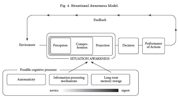
The Performance Shaping Factors (PSF) as occurring in a BDR situation may lead to critical situations caused by human failures. One of the most important PSF is Situational Awareness.
Situational Awareness can be defined as the human percipience of the condition of an environment within an operational process. Situational Awareness has three (3) levels:
1. Perception, the cognition of the situation;
2. Comprehension, interpretation of the recognized situation;
3. Projection, estimation of the consequences of the situation.
Ideally, decisions are taken based on these three pillars, resulting in a changed environment in which new situational awareness is being established. Evidently, this process is iterative and will take place for every situation/incident within the Battle Damage Repair process, which is shown in the following picture. The quality of the model depends on other PSF, such as availability and presentation of information, communication but also experience of the individual.
Another way of decision making is called ‘automaticy’, or an automated (conditioned) response. Although a certain level of experience or routine can increase the quality of decision making, automaticity is not the desired response on situational awareness and might result in human error.
Elimination of the occurrence of this effect can be realized by optimizing the Man Machine Interface, which was tested during the prototyping sessions and during the evaluation after delivery.
Workflow analysis approach
For gaining the actual deeper insights on the operational workflow of our IPMS-users, a workflow analysis was conducted according to the so-called GIVS-method. How this GIVS method works will be explained later in this paragraph. The research questions for this type of research were as follows:
• Which specific tasks can be distinguished per employee during a battle damage repair process?
• What specific information is needed to carry out each of these specific tasks?
• How do they gain this information? By consulting colleagues/ looking up the IPMS, using artefacts/relying on their own experience?
• When does decision making occur? What kind of information is used to make the decision and what are the consequences?
• In what parts of their workflow do they have to compose/update/revert to situation awareness (external/internal battle) in mental models? What kinds of information do they use to do so?
• What problems do occur during a procedure? When do they occur and what are possible causes and/or consequences?
To gain insights in the deeper layers of their workflow the the GIVS-method is applied, or better known as Generative Interview Visually Supported. GIVS is a common interview tool, to reveal the aspects as named in the research questions. By doing so, each of their personal tactics can be revealed in a one on one interviewlike session.
Internal Battle / Battle Damage Repair
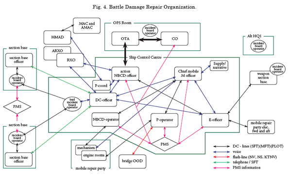
In order to understand the task analysis first the state 1 Battle Damage Repair (BDR) organization of a typical frigate that was analyzed is presented in below Fig. 5.
The BDR Organization picture illustrates the extent of manpower and information flow involved in managing the ‘Internal Battle’; the collective term for all activities to recover the maximum possible war fighting capability that supports the command aim after having suffered serious damage.
The purpose of the detailed task analysis described in this paper is to identify the tasks performed by the management team in the BDR organization that can be automated.
The Damage Control (DC) officer is in charge of this process. He directs the section base officers who manage the fire-fighting teams in their section, each covering half the ship. In the traditional situation the DC-officer and the section base officers share a number of tasks
Well trained section base officers will perform most of these tasks autonomously but they have to check their actions with the DC-officer and make sure the information is provided to him. For this reason the tasks the DC-officer and section base officers perform are presented in one column in the task analysis. Incident board operators support the DC-officer and section base officers. They keep the incident board up to date and communicate information to all other incident board operators, 6 in total. In the traditional situation two IPMS operators support the DC-officer, one operating systems and one executing electrical isolation under supervision of the Electrical (E) officer (DCO-L). However, they also perform tasks for the Mechanical (M) and Weapons-officer. The tasks the operators perform are presented in one column of the task analysis.
Patrol Vessel Battle Damage Repair Task Analysis
The purpose of a task analysis in this context is to identify the main drivers of the BDR organization. The scope is limited to the Platform Management System and thus the Damage Control and Marine Engineering Repair organization. It does not take into account the Combat Management System; the analysis excludes the Weapon Engineering repair organization. Of course, further integration of both organizations and corresponding management systems would be a significant improvement and will be a challenging subject for a future (integration) paper.
A rough Subject Matter Expert assessment describes the percentage of time BDR management spends on generic tasks. These tasks are subdivided in:
1. Gathering information (through communication and plotting),
2. Assessing information (to obtain situational awareness),
3. Decision making, and
4. Acting.
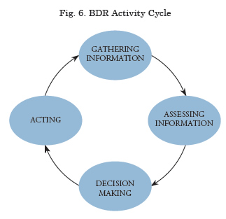
As illustrated in the above Fig. 6, these actions are performed in a continuous cycle, in accordance with the Situational Awareness Model of the previous chapter.
The task analysis was performed by a working group of Royal Netherland Naval officers, which all performed the role of DC-officer in their career, supported by an automation expert. The authors were part of this working group. The results of the task analysis are presented below.
Author’s comment:
To incorporate Human Factors in the design of a new system it is necessary to identify, analyze and describe all functions that the system will perform, to be able to allocate functions or tasks to a person or technology. In the case of a ship’s platform systems, this often exceeds the boundaries of the automation that is installed to actually control and monitor the installations. For an interdisciplinary or integral Platform Management approach, it is necessary to understand function allocation strategies.
A good example of flexible allocation is the autopilot in an aircraft or on a vessel, where highly trained and experienced operators can decide allocation of (sub)tasks to a highly complex control system.
Also, Operational Readiness functions have to be maintained and managed with Platform Management Processes or Operating Procedures. By nature, these procedures / protocols are interdisciplinary and require a multi-level organization to manage, operate and maintain both Platform and Weapon systems. In order to achieve this, Operational Readiness Functions (Operation & Maintenance) have to be projected/mapped on actual Platform/Weapon interdependencies on an installation/component level, i.e. Functional Chains.
At this moment, these functions are neither integrated nor allocated in a (superordinate) automation system and therefore these complex tasks are left to the operators. In particular during live or exercise environment or scenarios this results in high cognitive and communicative loads.
Furthermore, the nature of these interdisciplinary tasks and functions like Battle Damage Control and Sewaco Support unavoidably leads to high cognitive and communicative loads.
Task Analysis of Battle Damage Repair
The task analysis results show that the firefighting management process includes numerous task performed by the DC-officer and section base officers, most taking place within the first 5 minutes after fire detection. Many of the tasks and corresponding actions directly affect the situational awareness, and are, by nature, iterative resulting in high communicative workload. Correct functioning of the BDR organization is further complicated as a result of the different locations in the ship and verbal communication doctrines.
The introduction of FFDC IEIB on the OPV provides a shared information space and reduces the required communication. This can potentially reduce the amount of plotters.
However the mere quantity of tasks the section base officer and DC-officer need to perform in the first 5 minutes after an incident remains large. Therefore, it was also investigated what tasks of the fire-fighting organization can be automated in order to support manning reduction.
In order to understand the results of the task analysis first the generic tasks and how these are performed are described. Subsequently an estimate is given of the time spent on these tasks by the BDR team.
Gathering information, narrative
The information on the extent of damage after a hit of the ship by external projectiles is gathered by executing a physical ‘blanket search’ by the crew of the ship while in parallel the IPMS generates alarms that indicate potential problems.
With the ‘blanket search’, every single compartment is physically checked by teams of two crew members that subsequently vocally report the damage through the BDR organization following the communication lines illustrated in the BDR Organization. This means information on the damage is communicated to the SCC and ultimately the NBCD Officer over 3 to 5 levels.
Damage related to leakages and fires is first gathered in the section base by the Section Base Officer (SBO) and plotted on the incident board by the section base plotter there. Subsequently, this information is verbally communicated to all other stations, including the SCC, through the plotter over a DC communication line. At these stations this information is plotted again on the incident board. Therefore, the quality of the information on the incident board strongly depends on the quality of communication that takes place under stress. It is clear that the information on the incident boards often is out of date, incomplete and inaccurate, even if the information is available at the section base. It’s also evident that this communication and plotting process is very manpower intensive. Fortunately the information on the SCC incident board is available for the whole SCC team.
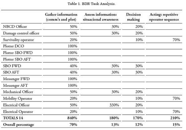
Damage related to mechanical and electrical systems is communicated to the Mechanical and Electrical Officer respectively. These officers gather this information on their personal state board and subsequently report their top priorities to the NBCD Officer and other team members that need to know. Again, the gathering of information is manpower intensive. The information on the incident boards is often inconsistent, of a low quality and not available for the whole SCC team. Plotters and messengers spend 100% of their time on gathering and presenting information, the managers in the SCC an estimated 50% of their time, the SBO’s around 40% or their time as they have their individual plotters and a single hierarchical structure and the operators in the SCC around 20% of their time as their primary task is operating the ships systems through the IPMS. The numbers are presented in the table below.
Assessing information
All the managers in the SCC and in the section base need to assess the incoming information to obtain situational awareness. Although not always consistent and often inaccurate the DC incident boards provide a good means to obtain situational awareness on DC incidents for all managers in the SCC. The availability of technical systems, although often indirectly available in the Platform Management System.´(IPMS) is not presented in any way to the management, other than scrolling through the enormous amount of MIMIC presentations in the IPMS. Therefore every team member acts on the information he or she has available for him- or herself on the personal state board. It needs no explanation that the situational awareness of the team is not consistent and often inaccurate. In order to overcome this operators and managers maintain handwritten lists of system availability that are stuck to the SCC wall to release information for the whole team.
The managers in the BDR organization on average spend 30% of their time on assessing information, as presented in below Table 1.
Decision Making
Because information is not presented in a structured way and because information has to be gathered from multiple sources that do not communicate related information simultaneously, only very limited time is available for decision making. What makes it even more challenging is that often decisions are requested from the lower hierarchical levels but the information required to take the right decisions is not readily available. This has two effects: The quality of the decisions is not optimal and the time spent on decision making is very limited: estimated between 10 and 30% of the available time. Again these numbers are presented in the table.
Acting
Acting comprises:
1. Execution of operator sequences determined in the analysis and
2. Deployment of Battle Damage Repair teams (to fight fires, stop leakages and repair systems).
The execution of operator sequences under stress often causes errors and takes the focus away from sufficient communication and maintaining situational awareness. Therefore SCC officers are all supported by an operator. The execution of repetitive operator sequences requires significant manpower and the high workload of the operator causes operator errors. The operators are executing operator sequences (that can be automated) 70% of their time spending their remaining time on communicating their actions to the SCC officers.
The deployment of Battle Damage Repair teams takes the reverse route of the information on the incidents. Due to the overload of communication lines often the deployment of these teams is delayed as officers are awaiting confirmation of their priorities and thus where to send the limited amount of resources. The time spent on ordering the deployment of Battle Damage Repair teams is included in the tasks decision making and communication (gathering of information taking place in both directions).
Conclusions of task analysis
To build up the desired awareness of the overall damage situation the management of the Damage Control Organization spends approximately 50% of her time on communication. Communication between the scene of an incident and the Ships Control Centre may take place over as many as 5 levels. This is time consuming and still can result in an incomplete picture. The Damage Control Organization requires a system that achieves significant reductions in the amount of communication and related workload and provides a consistent situational awareness across the BDR organization.
In order to make the right decisions, the technical management in the Ships Control Centre (the NBCD officer, the mechanical officer and the electrical officer) requires a good overall awareness of the situation. On today’s ships, these officers rely for 80% of their information on communication even though the information on the status of all technical systems is available in the IPMS. The technical management in the SCC requires a system that provides a clear, commonly accessible, overall picture of the technical systems and their status in relation to the Command Aim.
The operators in the Ships Control Centre experience a high workload. This is partly caused by the time required for repetitive operator sequences and high communication and cognitive loads. A system is required that automates repetitive sequences and assists the operator in analyzing the effect of alarms, can reduce the workload and increase the effectiveness of the operator.
Design of Task Oriented Based FFDC Applications
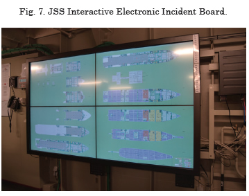
Interactive Electronic Incident Board
One of the first objectives of the FFDC Workgroup was to re-design the electronic plotting aids. This resulted in an Interactive Electronic Incident Board that combines a conventional plotter screen with a distributed FFDC automation and Multi-Touch displays. This feature also allows presentation of other applications, such as CCTV, which provides immediate access to visual information about the scene of the incident directly on the IEIB displays.
This FFDC application ensures that entered information is distributed to all electronic incident boards and workstations across the ship, ensuring the available information is consistent across the ship. This also includes interfacing with ships’ automation system with information of fire detectors, doors, hatches, etc.
This FFDC application ensures that entered information is distributed to all electronic incident boards and workstations across the ship, ensuring the available information is consistent across the ship. Th is also includes interfacing with ships’ automation system with information of fi re detectors, doors, hatches, etc.
From every FFDC position it is possible to plot symbols like fi re, boundary cooling and smoke boundaries, either through mouse and keyboard, or via multi-touch displays. Every type of symbol has its own specifi c properties and stages. Th e plot symbols are electronic version of the symbols defi ned in the Royal Netherlands Navy standard KN 15750. Th is makes it easy for personnel on board to switch from the conventional incident board (where the plotter draws the symbols by hand) to the FFDC HMI.
Selecting a plot symbol from the library and dragging it into a compartment is a user-friendly approach for placing a symbol on a desired spot. Subsequently, the state and time of the symbol becomes automatically available on all FFDC stations. In the FFDC HMI all kinds of features have been implemented to meet requirements for optimal control of the application, particularly under stress conditions. In the FFDC overview screen it is possible to present all kinds of important information for BDR. Th e FFDC HMI stores this information in layers. It is important that at any given time only the relevant and required information is presented; other information layers can be hidden.
Examples of information layers are:
1. A and B-type fi re wall layer;
2. Citadel information layer;
3. Safety and fire equipment layer;
4. Hazardous equipment layer.
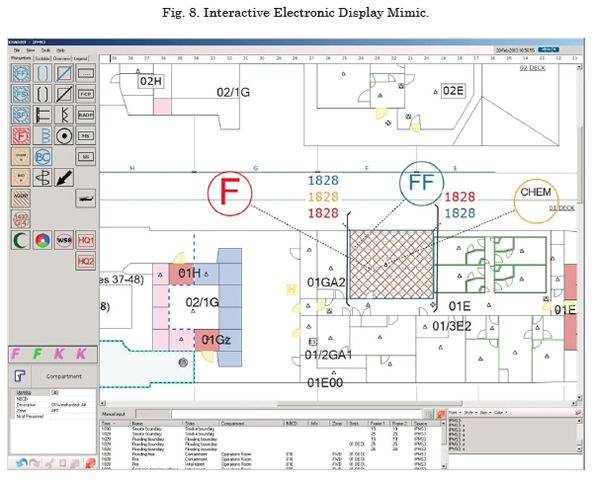
A free scribble option of the FFDC HMI gives the operator the possibility to draw (and share) lines (e.g. attack and evaluation routes) and to place texts in the Deck view window of the FFDC plotter screen.
The IEIB was specifically designed and tested to increase situational awareness while at the same time reduce communication.
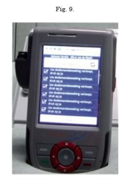
Wireless Hand-Held Devices
A second application that resulted from the working group are the Hand Held devices, or PDA’s that are deployed on the Holland Class PV. Engineers can use PDA’s to display the status of the systems when operating the equipment, during planned maintenance and in case of incidents. As a result, the Ship’s Control Center can be unmanned, while duty personnel are ‘online’ and have access to the designated systems anywhere on the vessel.
For Battle Damage Repair the integration of wireless connected handheld devices can be used to optimize local tasks/actions and increase situational awareness. For example, the handhelds allows team leaders to directly enter information from the scene of the incident into the FFDC system, while the FFDC system ensures that information is shared almost instantaneously and can make plotters redundant.
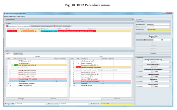
Battle Damage Repair Procedure Application
A system to program and execute BDR procedures is under development that can automate repetitive sequences and assist the operator in analyzing the effect of alarms, thus reducing workload and increasing the effectiveness of the operator.
In general, it is not too difficult to automate functions and sequences, a feature which is already incorporated in Imtech Platform Management System (IPMS).
However, as mentioned in chapter 2, automaticity also has drawbacks and BDR automated sequences have to be specified way in advance when the software is configured or hard coded. This is particularly the case for sequences that depend on the various conditions or sensor information. This causes another serious drawback as the definition of procedures depends heavily on experience which is obtained over the life cycle of a ship.
This insight initiated the requirement of the Royal Netherlands Navy for an Advice Builder, an application that enables designers as well as operators to assemble procedures during the engineering phase and during the time that the ship is in service. The Imtech IPMS used on modern ships of the Royal Netherlands Navy already includes ‘Apps’ that allow external systems to give commands to virtually any ship system that is monitored and controlled by the IPMS. That enabled the workgroup to acquire a better understanding of the real requirements. This resulted in an application comprising four parts:
1. a Procedure Module in the IPMS filled with the available procedures;
2. a dedicated HMI interface to the operator;
3. ‘App’ within the IPMS responsible for executing the triggers and steps;
4. an Advice Builder to be used for configuration of the procedures.
The Procedure Module resembles a database filled with procedures that have been designed, and subsequently tested, on shore-based facilities. The ‘App’ within the IPMS will start a specific Procedure once the pre-defined condition of that Procedure is met. There are 3 types of procedures
1. Alarm procedures are procedures initiated by the activation of an alarm. These procedures are often used to handle problems of platform systems;
2. Engine Room Emergency Measures are procedures relevant to the safe navigation of the ship. These can be initiated by an alarm or from a comparison of in the IPMS available plaform signals;
3. Killcards are procedures which can be selected by an operator via a drop-down list box in the IPMS mimic. The Killcards are sorted by section, deck, position and type of killcard (Fire, Energy, Flooding).
Procedures are presented in a dedicated IPMS Procedure Mimic. In mode Auto, the procedure ‘App’ will carry out the procedural steps. In modes Semi-Auto and Manual, the procedure App will wait upon operator acceptance. Each step implies executing a command and waiting upon start conditions for the next step. Below Fig. 10 shows the HMI of the IPMS Procedure Module. The 10 buttons on the left side of the procedure mimic depict the active procedures and the type of the procedures. The color of the buttons indicates the status of the procedures: Green for active and Red for a failure of a procedure.
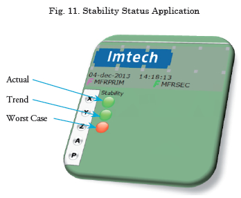
Stability Management System (currently under development)
The stability management system shows the ship stability in the event of an incident. Normally this will only be the tank levels for they have a major impact on the ships stability. But there are more events that can cause ship instability on board, of any kind of vessel. One of this causes are leakages, whether they are internal leakages (oil leakage, defective pipes, water used for fire extinguishing, etc) or external leakages (collision or impact damage) they can play a crucial part in maintaining the ships stability.
Within the Interactive Electronic Incident Board it is possible to set leakage plot symbols on the general arrangement containing information about the kind of leakage (oil, water, etc.) and a list of all the known water levels related with the leakage.
Together with the water levels, this information will be automatically processed by a ships stability application which calculates the impact on the ships stability. As a result, the IEIB will show the user three stability states each with three severity indicators:
• Green - No danger for ships stability, no further action needed.
• Orange - Possible danger for ships stability, further action desired.
• Red - Ship stability is in grave danger, instant action needed.
The Stability Management System gives the crew a comprehensive status of the current stability and where it might lead to if no counter actions will be made. And because it is all integrated, the crew will only have to update the IEIB which saves time feeding the system with stability information.
Future Developments
Operational Maintenance Support Model
As a baseline for future integration of multiple technical disciplines and maintenance tasks, the RLNL developed an enhanced Battle Damage Repair Activity Cycle or ‘Operational Maintenance Support Model’, including following discrete elements and tasks:
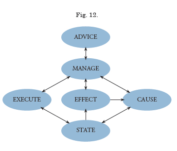
1. State: Operational State of the System and it’s components as indicated through the automation system or manually identified and documented.
2. Effect: Availability of the Function translated to other Systems and Capabilities.
3. Cause: Troubleshooting by means of Diagnostics (BITE) or through the experience and training of the crew.
4. Execute: Measures (Procedures) to correct malfunctioning equipment
5. Manage: Reduce the impact of malfunctioning and maintain the desired Capabilities
6. Advice: Interaction between operational objectives and Capabilities of the vessel.
As the State of discrete elements like technical systems and components form the foundation for this model, the information available within the automation systems (I/O, BITE messages) are paramount.
To predict the effect of one discrete element, operational requirements and platform capabilities must be decomposed or projected on the configuration of all participants that contribute to a particular function. This so called ‘Functional Chain Analysis’, has already been utilized in the diagnostic features of RNLN Combat Management Systems, however they exclude platform systems.
For future Frigate projects of the RNLN, this method will be applied to support maintenance and crew reductions by means of automation.
Platform/Weapon Integration
Th e CMS support systems typically consist of three important functions.
1. Power Generation
2. Electrical Distribution
3. Heating, Ventilation & Cooling (chilled water)
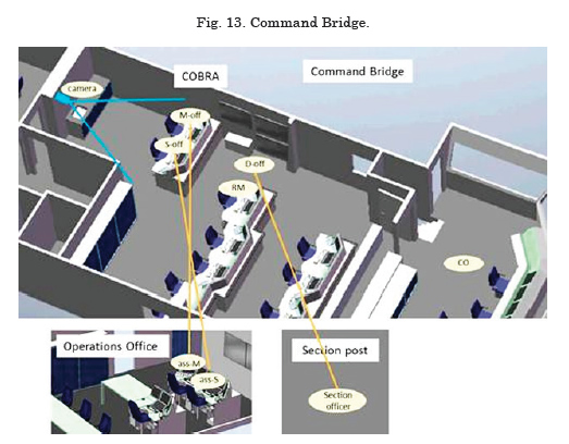
For the Holland Class PV, the functional dependency between platform and CMS was not integrated in the automation systems. However, to achieve the Operational Requirements with a reduced complement, the RNLN decided to develop a Command Bridge comprising of Navigation Bridge, CIC and SCC. Battle Damage Repair can also be directed from the Engineering Offi ce, depending on the operational scenario.
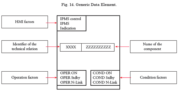
However, as mentioned earlier, for the future Frigate project, platform and CMS (automation) systems will be integrated using a generic data-bus system and diagnostic data elements including applications to process this information according the Operational Maintenance Support Model.
Distributed Intelligent Networked Control Systems
On board Royal Netherlands Navy ships many complex platform support systems exist such as cooling systems, electrical systems, and fire extinguishing systems. The complexity of these systems is hard to manage for the personnel, especially in case of emergency when reaction times have to be short. The problem is made worse by the decreasing availability of highly qualified personnel over the last decade. Both problems are reason for the Defence Materiel
Organization (DMO) to create control systems that can autonomously restore the functionality of the platform support systems in case of (battle) damage, taking into account the ever changing and uncertain status of these platform support systems.
The approach is to create intelligent components such as chillers, pumps, valves, sensors, and end users, and to give these intelligent components human-like reasoning. In real life, the human operator will always follow three steps when dealing with a damaged system, irrespective of the physical nature of that system: (1) isolating the damaged part from the rest of the system to prevent further damage; (2) finding new supply paths to the end users of the system so as to restore the system’s functionality; and (3) supplying the end users with the correct amount of what they need (e.g., cooling, electricity). In a research project performed by TNO, intelligent agents were created with three levels of intelligence that contain these steps. These agents communicate with each other through a shared network. If part of the control system is lost, the remaining agents are still able to communicate with each other and control the part they have access to.
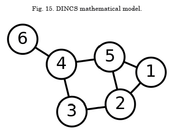
The DINCS engine or algorithm is based on a ‘Graph’ representation, similar to contemporary navigation systems, which is decomposed in following elements/definitions:
• Platform system comprises of:
Platform Devices (Pumps, Valves, Generators)
Connections (pipes, cables, ducts)
• Mathematically represented as Graph by:
Edges
Nodes
• Properties of Edges / Nodes:
One-direction
Cost (usage of resources, wear and tear (running hours))
Capacity
Priority
• Mathematics provided algorithms for:
Shortest path
Maximum flow
Minimum cost
The DINCS prototype is currently implemented for the fire mains system of RNLN LPD Rotterdam, as part of an upgrade of the (Imtech) automation system.
Conclusion
Operator Load analysis are paramount in the development of future Automation Systems, in particular Damage Surveillance And Control systems. The development of applications must incorporate operational management as well as functional interrelationships between platform systems. As a result application of technological advances can only be realized in close cooperation with intended users and designers. For the Patrol Vessel of the RNLN this was realized by a joint project team, task- and workload analyisis supported by a rapid prototyping development model.
This working method not only proved very effective but also unveiled substantial potential for future developments, which RNLN will implement successively.
Acknowledgements
This paper contains a logical compilation of earlier studies performed by Imtech and personnel of the Netherlands’ Defense Material Organization. Although major authors have been listed, the proceedings described in this document, surely could not have been established without the commitment of the FFDC workgroup members, the project teams and many other people who have contributed to the fundamental research.
References
E.J. MIDDELDORP, N.A. Badon Ghijben en R.D. Geertsma, ‘Advanced PMS functionality in the Royal Netherlands Navy: automation to support the internal battle’, proceedings INEC 2012.
S.C. HORENBERG and A.C.F. MELAET, ‘Uniting Weapon- and Marine knowledge – From goal to reality’, proceedings Engine As A Weapon 2013.
R.D. GEERTSMA, J.C. SCHREURS, D.J.M MEIJER and E.J. MIDDELDORP, ‘Integration of combat & platform management: developments in the Royal Netherlands Navy’, proceedings Engine As A Weapon 2013.
W. VAN DER ZWAN, ‘Task oriented design of Integrated Platform Management Systems’, 14th International Ship Control Systems Symposium (SCSS) in Ottawa, Canada, 2009.
J. RASMUSSEN, ‘Information processing and human machine interaction: an approach to cognitive engineering’, 1986. ISBN 9780444009876.
NETHERLANDS’ MINISTRY OF DEFENCE, ‘Diagnostic Support Guideline for new ship programs’ directive, undisclosed.
DIN EN ISO 13407, ‘Human centred design processes for interactive systems’, 1999. Remark: superseded by ISO 9241-210.
K.S. VAN BODEGRAVEN, ‘Intelligent Control Systems for Navy Ships’, 2010.