Infrared Signature Analysis of Surface Ships
Análisis de la firma infrarroja en buques de superficie
Stefany del P. Marrugo Llorente1
Vladimir Díaz Charris2
José M. Gómez Torres3
Abstract
The process of analyzing IR signature of a vessel is described in this document, which was developed using the ShipIR/NTCS software. As important aspect of the process, highlighting the pre-processing stages of the geometry under study and characterization of the environment. This document contains the results obtained for different background conditions, varying the type of sensor used, their distances and height measuring speed vessel under study and the time of day.
Key words: Infrared (IR) signature, MWIR, LWIR, IRSS, ShipIR.
Resumen
El documento describe el proceso de análisis de firma IR de un buque, el cual fue desarrollado empleando el software ShipIR/NTCS. Como aspecto importante del proceso, se destacan las fases de pre-procesamiento de la geometría bajo estudio y caracterización del entorno. El documento contiene los resultados obtenidos para condiciones de fondo distintas, variando el tipo de sensor empleado, sus distancias y alturas de medición, velocidad del buque bajo estudio y el momento del día.
Palabras claves: Firma Infrarroja (IR), MWIR, LWIR, IRSS, ShipIR.
Date Received: October 24th, 2014 - Fecha de recepción: 24 de octubre de 2014
Date Accepted: February 2nd, 2015 - Fecha de aceptación: 2 de febrero de 2015
________________________
1Corporación de Ciencia y Tecnología para el Desarrollo de la Industria Naval, Marítima y Fluvial; Gerencia de Diseño e Ingeniería; Cartagena, Colombia.
2Corporación de Ciencia y Tecnología para el Desarrollo de la Industria Naval, Marítima y Fluvial; Gerencia de Diseño e Ingeniería; Cartagena, Colombia.
3Corporación de Ciencia y Tecnología para el Desarrollo de la Industria Naval, Marítima y Fluvial; Gerencia de Ciencia, Tecnología e Innovación; Cartagena, Colombia
............................................................................................................................................................
Introduction
The integral design of any naval superstructure must consider two basic factors that allow the increasing of survivability in the specific operating environment: reduced vulnerability and low detectability.
This implies "design platforms that distort as few as possible the environment in which they operate, increasing in that way, the difficulty for detection, classification and acquisition by enemy weapons. Similarly, designs must be designed to minimize the effects of damage caused by the impact of enemy weapons" (Sierra & Vilchez).
As is known, all objects within our range, due to they are at a temperature above 0º K, emit thermal energy in the IR region of the electromagnetic spectrum. This radiation source may be employed for detection and monitoring by a gun provided with infrared sensors.
The spectrum of emitted or reflected energy of a ship or the way to modify certain physical parameters of the environment, are characteristic of each unit, so that is the reason why we talk of signatures. IR signature is the one associated with the electromagnetic radiation emitted in the infrared wavelength range.
The goal of this paper is to describe the methodology for obtaining and analyzing IR signature of a ship, showing the tools and procedures that were used, as well as design recommendations to be considered during the early design stages of a vessel, in order to reduce IR signature.
IR Signature basic concepts
Sierra & Vilchez [1] stated that "for an object can be detected, must be distinguished from the surrounding environment. Therefore, the principles on which the reduction IR signature are based, consist on the reduction of the temperature differences between the surfaces of the vessel and the environment and reduction of the temperature of the exhaust gases", that is why is essential to identify the sources of IR radiation on ships, in order to find mechanisms to reduce it.
In general, the IR signature of a vessel consists of two components: those generated internally and those that are generated externally.
Internally, the main sources of generation include the heat emitted by engines and other equipment, engine exhaust gases and air ventilation systems; however, most internal IR source comes from the main machinery on board, especially from electric motors and generators.
Externally, IR signature is the result of absorptions and/or reflections on the ships surfaces, of the radiation received from their environment. The main sources of radiation in the environment are: the sun, the sky radiation and the sea.
For an effective IR signature reduction of a ship it must be considered both, internal and external sources.
General Design Concepts
The IR signature management has become very important for modern warships. In fact, now a day it is essential to use sophisticated computational design tools that allow designers to handle ships IR characteristics of a ship, before its construction.
The purpose of such simulators is to predict, analytically, ship IR signature and evaluate how vulnerable to an enemy IR detection could be, through a wide range of operating and sea conditions.
Some of the existing simulation tools, for modeling and evaluation of ships IR signature are: ShipIR/ NTCS, RadThermIR and OSMOSIS.
Simulators use specifications
Input specifications are all parameters that affect platform susceptibility against threats, including:
• Background: Geography, date and time, weather.
• Platform: Size and shape, materials and coatings, propulsion and auxiliary equipment, deck and deck maneuvering equipment.
• Threats: Bandwidth (MWIR, LWIR), spatial resolution (scanner, image management, etc.), sensitivity (noise detector, confusion.).
The above are inputs for tools like NTCS, used to perform analysis, incorporating the 3D model of the platform, the realistic effects of sea and sky, multiple reflections from the surface, atmospheric attenuation and chimney emissions.
In general, the use of computational models allows sensitivity studies that would be extremely expensive to do through experiments or that are not possible due to logistical reasons. Some of the research topics that can be analyzed using such tools are:
• The effect of the sun's position in the surface temperatures of the ship.
• Estimate the ship’s signature from any location of the observer.
• Identify hot spots contributions to the detection susceptibility.
• Objectively compare the effectiveness of different options of IR suppression in identical operating conditions.
IR Signature Suppression (IRSS) techniques
The most modern ships in the world include mechanism of IRSS to reduce ship’s susceptibility against missiles guided by IR sensors. The recent year’s trend of new ship’s development programs shows more systematic and comprehensive designs that are more approximated to IRSS, those designs include studies to analyze the susceptibility of the ship and the cost-benefit analysis of designs, which means that new ships are being designed with low signatures and increased survivability.
Below deck IRSS
To eliminate or minimize the severity of hull’s hot sections and sides of the chimney, is required to make use of basic thermal design. Compartments must be vented enough, in order to maintain temperatures below the 50° C inside the compartment. Any compartment or chimney space that could be heated above room temperature will require thermal insulation applied into all external bulkheads.
Apply a 25 mm (1") fiber glass insulation can reduce external surface temperature to an acceptable temperature contrast. As a guideline, surfaces of the hull that are heated from inside should not exceed a contrast temperature of ±5°C.
Other compartments around the ship that may have different ambient temperature, must be considered. Negatively contrasted surfaces resulting from fans, air conditioning in electronic assemblies, for example, must be avoided too.
It is possible to use different IR suppression levels, which are mainly applied to the engine exhaust system and ships surface.
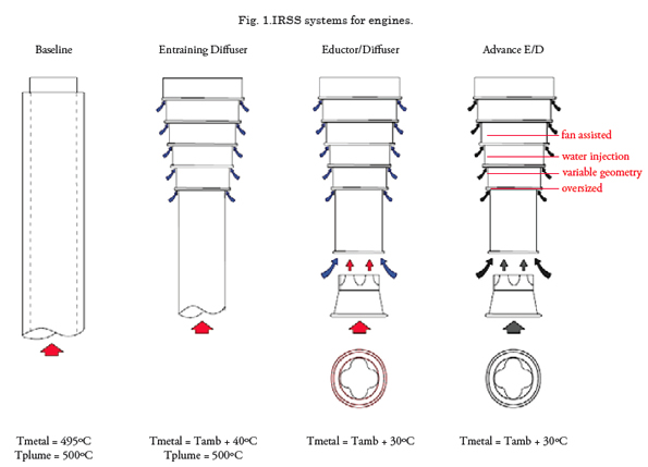
There are four suppression levels for the engines exhaust:
• No suppression
• Visible metal cooling to + 30°C ambient
• Metal cooling + chimneys cooling up to 250°C
• Metal cooling + chimneys cooling up to 150°C
Fig. 1 (pag.60) shows a number of systems currently in use for IRSS.
These systems incorporate a layer of air cooling and exhausts. For some systems, the irrigated water is used to reduce the chimneys temperature.
IRSS en la superficie de la plataforma
The platform surface signature is due to the heating by the sun and heat loss from the interior spaces.
The solution for the heat losses is to use internal insulation and ventilation, while for the sun heating the solution is to use water cooling and low solar absorption paints.
Special paints
According to Vaitekunas, Th ompson and Birk [3], the selection of special paints is a very complex issue and there is no single correct answer. Th ere will always be a balance between the best solution for sunny conditions versus the best solution for the conditions at night or cloudy days.
For example, under sunny conditions, the hull paint must:
1. Not to absorb solar radiation below 3 micron wavelength (i.e., low emissivity with short wavelength)
2. Absorb all radiation above 3 microns (i.e., high emissivity of medium and long wave).
Th is type of spectral painting is available but it is expensive and its eff ectiveness can be drastically reduced by surface contaminants such as rust, dirt, etc.
Under overcast conditions, it would be desirable to have low emission paints. In this case, the ship would emit less and refl ects the environment. Note that the low emission gradually tend towards greater emission due to factors such as the accumulation of salt, engine exhaust, soot and dirt.
Water Shower
Authors of [3] stated that this suppression technique involves the active cooling of the hot parts of the surface of the ship with seawater.
It is necessary to be careful of not to cool so much the surfaces of the ship. A high negative contrast imposes an eff ective target to modern browsers. By using a feedback system, water shower could be activated and/or deactivated according to the needed, keeping the surface of the ship at a constant temperature of low contrast.
Cloud of water mist
About this particular, experts [3] indicate that a thick cloud of water mist is sprayed onto the ship, hiding the ship from the point of view of IR seekers. Th ere are not data about the effi cacy of this type of system as an IR countermeasure. However, if this system is handled properly, it can improve the performance of other countermeasures such as decoys.
Some problems of a water mist system are the darkening of optical sensors on board, and the accumulation of salt at spray nozzles and over the entire surface of the ship.
Uses of any of these three methods as hull IRSS do not eliminate the requirement of proper insulation and ventilation design and use of suppression techniques for main machinery.
IR signature analysis of a platform
Th e aim of this section is to identify how the IR signature of a surface platform type Fassmer OPV- 80 and the way how this varies depending on changes in their environment. Th e software used for analysis is ShipIR / NTCS.
Platform
Requires initially have the geometry of the vessel, in this case, was available in the software Rhinoceros. It is necessary to model the hull and superstructure, as well as fl ares, windows or other openings that may exist airfl ow / gases.
Fig. 2, presents a table with the procedure for preprocessing of geometry under study.
Th e development platform is also made in Rhinoceros. Further, is necessary to use the Pointwise (commercial tool meshing) software, in order to make an appropriate meshing for IR 3D surface model analysis.
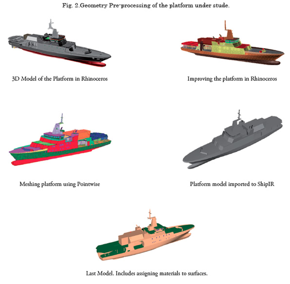
Th en the 3D model of the platform is displayed by Model View Editor (MVE) of ShipIR / NTCS software, which is possible to assign the characteristics of materials to surfaces.
Machinery
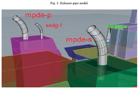
For a ship IR analysis, it is not necessary to model the 3D geometry of the main machinery, but it is important to understand fundamental aspects of them for assignment thermal characteristics to the surfaces of the vessel. Th is information is essential to characterize the conditions of exhaust required as inputs to the thermal model of IR signature, as well, is required to verify which is the power consumption in operating condition of the vessel, in order to know what equipment will being used in each case.
For this study, was taken into account the operating condition representing higher power consumption (ie, the worst condition) and simulations were performed.
Fig. 3 presents a model of the exhaust pipes on the ship under study.
Optical Properties
Was used a coating (paint) for much of the surface of the vessel type gray Admiral. It is important to know the characteristics and optical properties of this type of coating, since it will depend the IR signature variation of the vessel under study. Th is type of paint is used, because it is fully characterized and is not necessary to make additional fi eld studies to determine their properties.
Th e company W.R. Davis Engineering Ltd, who advised the developers of this work, provided information of optical properties of the coating used. Th e detail of each is explained in [4]. In general, it is determined solar coating as absorptivity αs=0.65 and thermal emissivity is εT=0.94.
Environmental Data
Th e right set of data describing the climatic conditions of the Colombian maritime zone for use infrared analysis of the unit under study is defi ned.
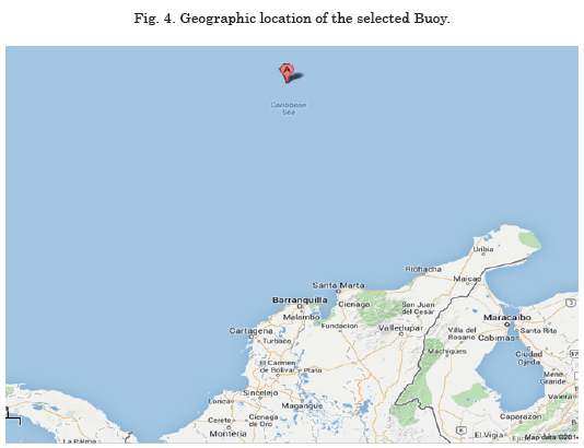
Th e data used is provide from the buoy # 42058 of US National Oceanic and Atmospheric Administration (NOAA).1
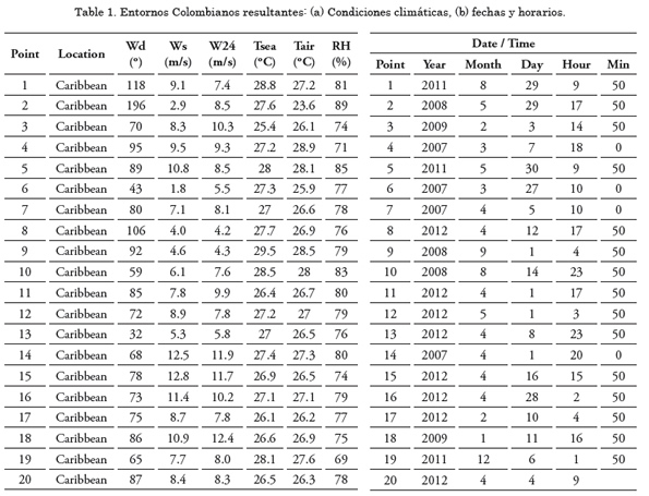
Th e buoy is located 15° N 75° W. It has historical data from 2006 to the present (36,759 points) and provides plane and graphical information to room temperature, sea temperature, relative humidity, wind speed and direction at each point. Spatial location is shown in Fig. 4. Twenty (20) scenarios (dates and weather conditions) were selected to evaluate the performance of the OPV - IR signature. Table 1 presents a list of scenarios used.
Results
Simulations in ShipIR / NTCS tool were made to the following conditions:
• Twenty (20) environments
• Two (2) speed vessel (12 Kts, 18 Kts)
• Two (2) times of the day θsun=30º,noche
• Two (2) operating bands sensor (LW, MW)
• Two (2) heights for sensors (10 m, 300 m)
• Two (2) distances at which is located in sensor (1 Km, 10 Km)
After the simulation process in ShipIR / NTCS tool 640 resulting fi les were obtained. For each of them is possible to analyze the OPV - IR signature, under conditions that were set.
In order to make a fi lter in the process, the scenarios presented IR signatures low, average and high (10%, 50% and 90%) were analyzed. For platform in these six (6) scenarios, polar graphs showing IR signature, low speed conditions, time of day, type of sensor and height thereof, mentioned at the beginning were developed. In all polar graphs, the bow of the ship is to 0°.
Fig. 5 shows the IR signature of the vessel under study to the following conditions:
• Six (6) environments
• Two (2) speed vessel (12 Kts, 18 Kts)
• Time of day (θsun=30º)
• One sensor operating band (LW)
• One height sensor (10 m)
• One distance sensor location (1 Km)
Fig. 6 shows the IR signature of the vessel under study to the following conditions:
• Six (6) environments
• Two (2) speed vessel (12 Kts, 18 Kts)
• Time of day (θsun=30º)
• One sensor operating band (MW)
• One height sensor (10 m)
• One distance sensor location (1 Km)
Th e peak observed on the horizontal axis of the polar graph in Fig. 6, is due to a radiation intensity contrast (CRI) negative.
It is important to clarify that only negative CRI occur within the band "solar glare" (near the solar azimuth). Th e image next to the polar graph shows the fl ash that causes this CRI. Generally this negative contrast is characterized by long spikes on the polar graph, to 270 from the bow of the ship.
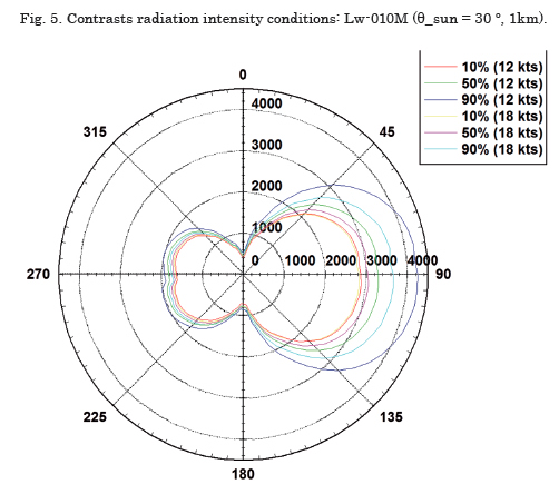
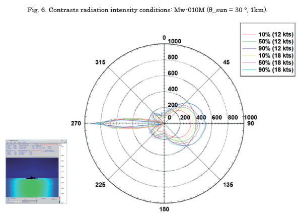
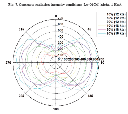
Fig. 7 shows the IR signature of the vessel under study to the following conditions:
• Six (6) environments
• Two (2) speed vessel (12 Kts, 18 Kts)
• Time of day (night)
• One sensor operating band (LW)
• One height sensor (10 m)
• One distance sensor location (1 Km)
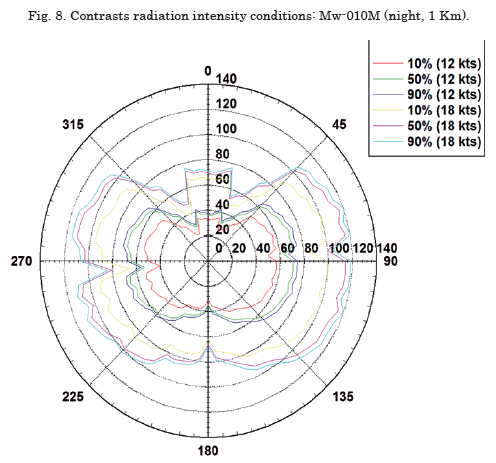
Fig. 8 shows the IR signature of the vessel under study to the following conditions:
• Six (6) environments
• Two (2) speed vessel (12 Kts, 18 Kts)
• Time of day (night)
• One sensor operating band (MW)
• One height sensor (10 m)
• One distance sensor location (1 Km)
Conclusions
It was possible to show in the case of the unit under study, in daylight, positive contrasts (due to the exhaust pipes) and negative (surface without sun exposure) can coexist on the same scenario and refl ected in some specifi ed scenarios for IR signature modeled.
"Corridors brightness" seen in half-wave sensors, are always negative. Th is because the background is always warmer than the ship, for reasons such as: Solar dispersion in the atmosphere (the sky) and the refl ected sunlight on the surface of the ocean (sea). Th is is usually more common when the shadow side of the ship is evaluated (during the day).
Th e signatures for night, they are often negative contrast. Surface temperatures are always lower than the air temperature (overnight) due to: the cold sky radiation (cooling) air convection (heat).
Low CRI not mean that it will also be under the detection range, since in the case of detection, the sensor is narrower in the area of analysis (engagable with one pixel), while the CRI surface discussed in general.
A great reduction in the detection ranges (stern / bow) with sensors in low and medium-wave located 300 meters indicates detection sensitivity due to the size of the target (i.e., the projected area of the ship).
Th e detection ranges (no sun) in LWIR are almost constant, with a small increase in the sides of port / starboard (due to hot chimneys) and considerably lower than those obtained during the day (without heating from the sun).
Th e ranges of detection (no sun) in MWIR have much larger oscillations, directly proportional to engine power (speed), with little or no reduction (compared to the day) - this indicates that the exhaust stacks (hot steel) are largely responsible for detection.
References
[1] SIERRA, Honorio & VILCHEZ, Francisco. Detectabilidad de buques de combate. Spain.1999. [On line]. Available in: http: //www.ipen.org.br/downloads/XVI/35_ detectabilidad_buques_combate.pdf
[2] W.R Davis & J. Thompson. Developing an IR Signature Specification for Military Platforms Using Modern Simulation Techniques. Ottawa, Ontario, Canadá. [On line]. Available in: http://www.davis-eng.com/docs/papers/ IR%20Signature%20Specification.pdf.
[3] D. Vaitekunas, J. Thompson & A.M. Birk. IR Signature Suppression of Modern Naval Ships. Ontario, Canadá. [On line]. Available in: http://www.davis-eng.com/docs/papers/ irss_paper.pdf.
[4] D. Vaitekunas, J. Jafolla, P. McKenna & M. Szczesniak. Measurement and analysis of optical surface properties for input to ShipIR. 2009. SPIE Proceedings Vol. 7300: Infrared Imaging Systems: Design, Analysis, Modeling, and Testing XX.
___________________________________________
1 Available in http://www.ndbc.noaa.gov/maps/West_Caribbean. shtml.