Solution to the Anti-aircraft Fire Control Problem on a Naval Platform Using the Direct Geometric Model
Solución al problema de control de tiro antiaéreo sobre una plataforma naval empleando el modelo geométrico directo
Francisco Gil 1
Andrés Vivas2
Abstract
To find the kinematic model in applications different from robotics, the free-body diagram and coordinate conversion using Euler angles is frequently used. In robotics the Khalil-Kleinfinger (1986) method is used (and others), which allows coordinate conversions over several joints. In this paper a new application of this method to solve the fire control problem of a naval anti-aircraft gun is proposed. To demonstrate the application a virtual model is built using Virtual Reality Modeling Language (VRML) and controlled by Matlab Simulink®. From the direct geometric model the solution of the problem is found, including the detection system, platform, gun and flight of the missile. This model serves as a tool for the design, testing and integration of controllers for the gun and detection system. The prediction algorithms of the trajectory of the target and the missile in flight models can also be integrated. The results show that the geometric model of complex systems with many degrees of freedom can be constructed in a precise, methodical and easy to understand manner.
Key words: Fire control systems, geometric model, modeling.
Resumen
Para hallar el modelo cinemático de un proceso o mecanismo en aplicaciones distintas a la robótica el método frecuentemente usado es el diagrama de cuerpo libre y la conversión de coordenadas mediante ángulos de Euler. En robótica se emplea entre otros el método de Khalil-Kleinfinger el cual permite hacer conversiones de coordenadas sobre varias articulaciones. Este artículo propone una nueva aplicación de este método para la solución del problema de control de tiro antiaéreo de un cañón naval. Para demostrarlo se desarrolla un modelo virtual utilizando Virtual Reality Modeling Language (VRLM) y se implementa el controlador mediante Matlab®. A partir del modelo geométrico directo se desarrolla la solución del problema incluyendo el blanco, el sistema de detección, la plataforma, el cañón y el proyectil. El modelo desarrollado sirve como herramienta para el diseño, prueba e integración de controladores para el cañón y el sistema de detección, para desarrollar los algoritmos de predicción de la trayectoria del blanco y modelos del proyectil en vuelo. Los resultados obtenidos muestran que se puede construir el modelo geométrico de sistemas complejos con muchos grados de libertad de una manera precisa, metódica y fácil de comprender.
Palabras claves: Sistemas de control de tiro, modelo geométrico, modelización.
Date Received: October 5th, 2014 - Fecha de recepción: 5 de octubre de 2014
Date Accepted: November 25th, 2014 - Fecha de aceptación: 25 de noviembre de 2014
________________________
1 Escuela Naval de Cadetes “Almirante Padilla”, Colombia. e-mail: francisco.gil@armada.mil.co
2 Universidad de Cauca, Colombia. e-mail: avivas@unicauca.edu.co
............................................................................................................................................................
Introduction
The classic problem of anti-aircraft fire control consists in the correct prediction of the future position of a target over the time in which it is intercepted by a missile (Berg, 1983). For naval antiaircraft fire, the weapon is on a platform that moves within six degrees of freedom, which requires maintaining the reference in orientation and displacement with respect to the world (Weiss, 1979) through an inertial navigator (I.N.S.) (Woodman, 2007). Additionally, the cannon, the detection system, the inertial navigator, and the platform’s center of gravity are in different places; thus, requiring further corrections.
A solution consists in employing numerical methods to correct the cannon’s orientation with respect to the line of sight (Elnashar, 2013), using the relative velocity between the target and the platform to predict the future position. This generates error when the platform is mobile, given that the relative velocity to the platform and the target’s absolute velocity are different. This error is greater inasmuch as the velocity of the platform is comparable to that of the target. In addition, the derived equations result complex and with many elements.
Wang (2012) employs the free-body diagram and coordinate conversion through Euler angles (Slabaugh, 1999) to find the kinematic model of a system with four stabilized cameras in an air balloon. This method develops conversions of coordinates successively, which also turns out complex due to the large amount of elements to treat. Conversion via Euler angles is used in multiple applications, including control of guided missiles (Ollerenshaw, 2005) and unguided missiles (Hahn, 2009); stabilization of cameras on vehicles (Zayed, 2007), (Kumar, 2008); dynamic models of underwater vehicles (Wadoo, 2011); and models of inertial platforms (Dongsheng, 2011).
A way to simplify the movement equations is to use the matrix representation of vectors. This reduces the number of coefficients necessary for control, making it easier to construct models with multiple inputs and multiple outputs (Fossen, 2011).
Fossen (1991) uses an inverse dynamic model to model a naval artifact with six degrees of freedom. This implementation conceives the artifact as a rigid body and it is used to design controllers for governance and stabilization systems. Cabecinhas (2012) uses a similar strategy for the dynamic model of a four-rotor helicopter.
Kim (2008) constructs a virtual model of a stabilization platform that works as a parallel robot capable of moving in six degrees of freedom. Through the inverse geometric model the length of six prismatic articulations is determined. On this virtual model, a drift (ronza) elevation system is tested for a machine gun and its respective sensors. This permits saving resources upon developing part of the field tests on the virtual model. Other tools may be employed to construct virtual models of weapons systems, like in Bo (2011), where Virtool and High-Level Architecture (HLA) are used.
Bearing in mind that the naval fire control problem can contemplate up to 14 degrees of freedom, it turns out complex to find its geometric model by independently performing coordinate transformations, with it being best to take advantage of the methodical manner of performing successive transformations as proposed by Khalil-Kleinfinger (1986). A variation is, then, proposed of this approach to construct a geometric model of the fire control problem, including platform movements and extending to integrate the movements of the target, the cannon located on the platform, and the missile in flight. This model will serve as a framework to design, test, and integrate controllers for the cannon or the direction of fire control. Bao-quan et al. (2010) designed a controller for a cannon’s servos on a virtual model. Upon developing a virtual model, huge costs are saved because this allows early detection of possible design problems and tests are reduced by using real surface units, real aircraft targets, and real weapons (Kim, 2008).
Solution to the fire control problem
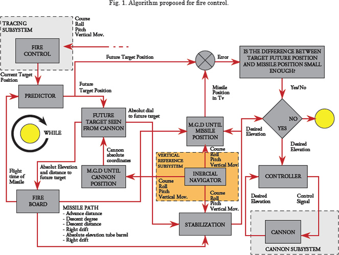
The following algorithm was designed to solve the fire control problem.
Monitoring Subsystem
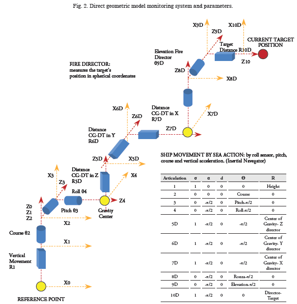
This determines the current target position in rectangular coordinates with respect to the platform position over the surface. This position is defined by the point projected by the platform’s center of gravity over the surface plane. The target’s position is measured through a fire control director that indicates compass bearing, elevation, and distance; thereafter, the coordinates are translated to the point of reference.
The direct geometric model of 0T10D is found and the target’s coordinates are obtained, thus:

Corrections to maintain the point of reference as fixed point
Unlike the robots normally modeled through the Khalil-Kleinfinger (1986) technique, in this case the point of reference moves on a plane. Due to this, it is presumed that for each discrete time the pointof- reference position is fixed and the prior target positions are corrected according to the platform’s displacement on the plane. It is assumed that the inertial navigator is 100% precise; however, in reality a deviation will exist.
A P matrix is defined, which keeps the target’s previous positions with respect to the point of reference that is always [x=0, y=0].
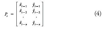
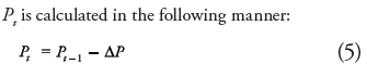
Where ΔP is the platform’s displacement in the sampling time, Δt. To find ΔP, measure the instantaneous acceleration delivered by the inertial navigator, ai, and calculate such through Newton’s laws of motion.
Where Vit-1 is the platform’s velocity in the prior time, which is calculated by integrating ai (Woodman, 2007). Pt and the target’s current position [xt, yt] are the inputs to the predictor to calculate the target’s future position.
Predictor of the target’s future position
By using any prediction algorithm, like the Kalman filter (Berg, 1982), from the known trajectory, the target’s position is sought in a future time equal to the missile’s flight time, tv. The problem is that the target’s future position is a function of the missile’s flight time, which in turn is a function of the target’s future position. To solve this, we first assume that the target’s future position is equal to the current position, hence, the missile’s flight time, tv, is calculated. This flight time serves to calculate a new future position of the target. When repeating this process several times, the difference between the target’s future position and the missile’s position in tv is reduced until it gets close to zero (Vila, 2009).
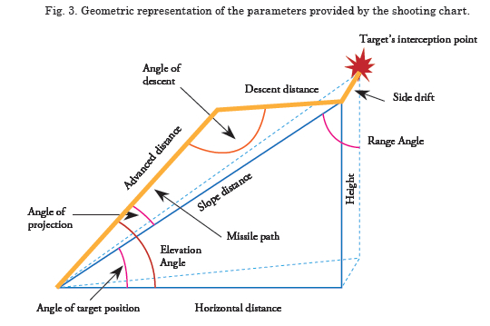
The missile’s flight time is obtained from shooting charts. Shooting charts contain the ballistic parameters of a given type of ammunition. These charts are elaborated by manufacturers and are determined experimentally. From the elevation angle and the distance to target, we find the cannon’s elevation angle, missile’s angle of fall in its terminal part, and the missile’s lateral deviation caused by the rotation on its own axis (Vila, 2009). Another way is to mathematically model the missile’s trajectory in the atmosphere based on parameters like the ballistic coefficient, initial velocity, and atmospheric pressure (Carlucci, 2007).
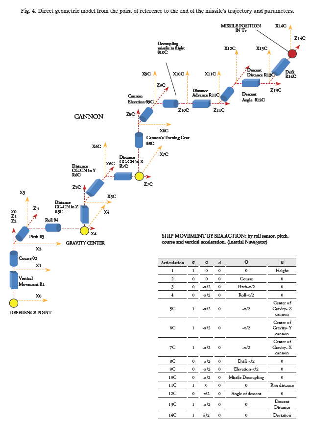
Direct geometric model from the point of reference to the end of the missile’s trajectory
The geometric model from the point of reference to the missile’s position in tv permits comparing this last position with the target’s future position at the same time, so that we can find a drift position and cannon elevation that reduces the distance between these two points to zero.
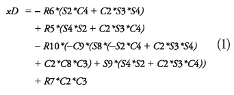
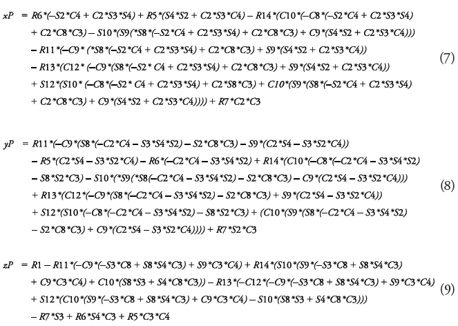
The direct geometric model of 0T14C is found and the missile’s coordinates at moment tv are obtained, thus equations 7, 8 and 9 (see page 49).
Calculation of drift and cannon elevation
To complete all the parameters of the direct geometric model, determine where the cannon should be aimed with respect to the platform.
For this, the platform aspect is characterized with respect to the world through three unit vectors: the vertical that describes the platform plane, the bow that describes the direction, and the starboard that is perpendicular to the previous two. These are found through the following direct geometric models, from data on course, roll, and pitch.

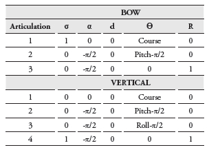
Finally, the coordinates of the bow, starboard, and vertical vectors of the platform are obtained, thus:
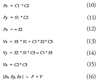
Upon defining the reference coordinates system, the necessary drift and cannon elevation are determined. For such, we determined the rectangular coordinates of the directions of compass bearing and elevation obtained through the shooting chart by constructing a geometric model equal to that described in Fig. 5 for the bow, except that the articulations are drift, elevation, and cannon tube, obtaining the coordinates of the directions of compass bearing and elevation obtained through the shooting chart, thus:

The components of this last vector are found in the directions of the vertical, bow, and starboard vectors performing the corresponding point products.
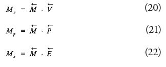

The component of the compass bearing-elevation vector in direction of the vertical vector permits finding the elevation, while the components in bow and starboard direction permit finding the compass bearing.
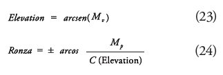
If vector Me ≥0 then the drift is toward the right (+), on the contrary it is to the left (-).
Missile decoupling
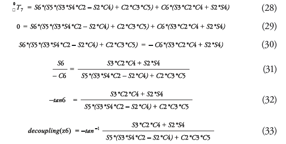
When the missile abandons the cannon tube to start its flight, it stops depending on the platform’s orientation; hence, it is necessary to maintain the plane formed by the rise distance and the descent distance when turning over the angle of descent, perpendicular to the surface plane. For this, the decoupling articulation must be turned. To find this turn angle, the following geometrical model is constructed. The rise distance-descent distance plane is perpendicular to the surface when the left unit vector (z7) is perpendicular to the zenith. This occurs when:
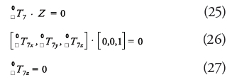

From the direct geometric model we obtain:
Results
To assess the model’s performance, a virtual model is constructed of a surface platform with a shooting director and a cannon, according to the geometric models described previously, using VRML (Cellary, 2012). The algorithm described in Fig. 1 is tested by using Matlab® Simulink®. The target’s trajectory is generated through a free-ware flight simulator, YSflight, (Yamakawa, 2009).
To simplify the predictor it is presumed perfect when taking the target’s future position in tv of the same trajectory recorded from the simulator. Likewise, the cannon’s plant model or its controller is not considered.
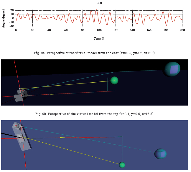
In the previous images, the cannon is toward the bow and is represented as a sphere with a thin cylinder, the shooting director is over the superstructure and is represented as a cylinder that is the base, and a cone whose fl at face represents the sensor that monitors the target. Note that the position of the cannon and shooting director is common and is taken as generic, but in practice it may be any over the platform, being this one of the advantages of this model because it permits modeling the position of the cannon or director in any part of the platform.
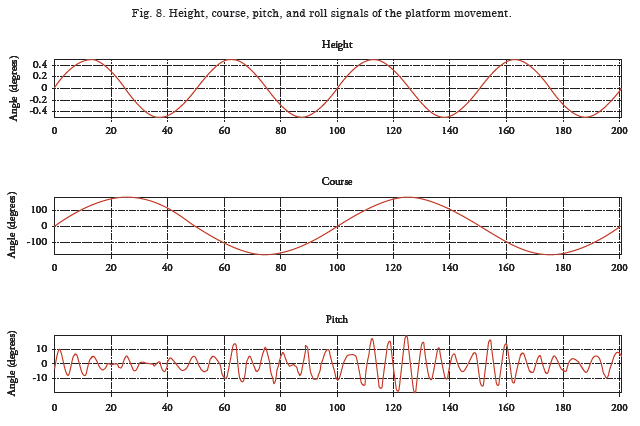
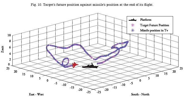
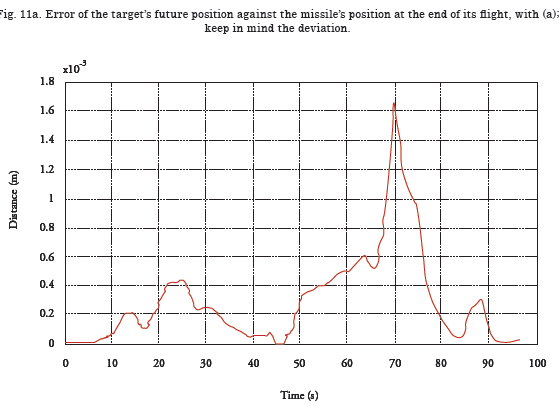
From a trajectory of a target and simulated platform movements the algorithm is tested, obtaining the results represented in Figs. 9 to 11.
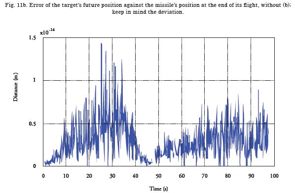
Fig. 11a shows an error of 8.58x10⁻⁸ MRS in the missile’s position with respect to the target’s future position. Th is error is because the shooting chart uses an approximation in the missile’s deviation. In Fig. 11b the deviation is equal to zero to observe the error attributable to the geometric model, with this error being 2.45x10⁻²⁷ MRS.
Conclusions
Th is article has presented a new application of the Khalil-Kleinfi nger method (1986) to geometrically model robots to solve the control problem of a naval anti-aircraft cannon shot, suggesting the applicability of this method to diverse problems.
This method facilitates the construction of the model, given that it simplifies the equations permitting easier design of controllers for the system.
The model developed serves as generic platform to develop a fire control system by integrating all the system’s components from the mean of detection to the missile in flight, being easily adaptable to multiple platforms including air and land.
Future work will include the development of the controller for a cannon and the prediction algorithm of the target’s future position.
References
BAO-QUAN, M. et al. Research on Dynamic Simulation of Remotely-Operated Weapon Stations Servo Control System. 2010 IEEE International Conference on Intelligent Computation Technology and Automation. China, Changsha, 2010
BERG, R.F. Estimation and prediction for manoeuvring target trajectories, IEEE Transactions of Automatic Control, Vol. 28, No. 3, March 1983, pp. 294–304.
BO, B., et al. Research of Anti-aircraft Gun Weapon System Simulation Platform Based HLA and Virtools. 2011 International Conference on Electronics, Communications and Control. China, Ningbo, pp. 4455-4457, September, 2011.
CABECHINHAS, D. Integrated Solution to Quadrotor Stabilization and Attitude Estimation Using a Pan and Tilt Camera. 51st IEEE Conference on Decision and Control. USA, Maui, Hawaii, December, 2012.
CARTLUCCI, D. and JACOBSON, S. Ballistics Theory and Design of Guns and Ammunition. CRC Press, Taylor & Francis Group. Boca Raton, Florida, USA, 2007. ISBN: 978-1- 4200-6618-0.
CELLARY W. Interactive 3D Multimedia Content, Models for Creation, Management, Search and Presentation. Department of Information Technology Poznan University of Economics. Springer. Poland. 2012. ISBN 978-1-4471-2496-2.
DONGSHENG L. et al. Research on Modelling and Simulation for Pitch/Roll Two-Axis Strap-down Stabilization Platform. The Tenth International Conference on Electronic Measurement & Instruments. The 54th Research Institute of CETC, Shijiazhuang, School of Instrumentation Science and Optoelectronic Engineering Beijing University of Aeronautics and Astronautics, China. 2011.
ELNASHAR, G. A mathematical model derivation of general fire control problem and solution scenario, School of Engineering-Egyptian Armed Forces. Int. Journal of Modelling, Identification and Control, Vol. 20, No. 3, Cairo Egypt, 2013.
FOSSEN, T. Nonlinear Modelling and Control of Underwater Vehicles. Doctoral Thesis (PhD). Department of Engineering Cybernetics, Norwegian University of Science and Technology. Trondheim, Norway. 1991.
FOSSEN T, Handbook of Marine Craft Hydrodynamics and Motion Control, First Edition. Norwegian University of Science and Technology Trondheim, Norway. John Wiley & Sons Ltd. Trondheim, Norway. 2011. ISBN: 978-1-119-99149-6.
HAHN R. et al. Predictive Guidance of a Missile for Hit-to-Kill Interception. IEEE Transactions on Control Systems Technology, Vol. 17, No. 4, July 2009. 1063-6536.
KHALIL, W. Y KLEINFINGER, J.F. A new geometric notation for open and closed-loop robots. 1986 IEEE International Conference on Robotics and Automation, San Francisco, USA, pp. 1174-1180.
KIM D. et al. Stabilization Control for the Mobile Surveillance Robot using Motion Simulator. Chungnam National University, Dodaam Systems Co. International Conference on Control, Automation and Systems. Seoul, Korea. 2008.
KUMAR J. Stabilization System for Camera Control on an Unmanned Surface Vehicle. Thesis. Naval Postgraduate School. Monterey, California, USA. 2008. NSN 7540-01-280- 5500.
OLLERENSHAW D. and COSTELLO M. Model of Predictive Control of a Direct-Fire Missile Equipped With Canards. Oregon State University. Corvallis, Oregon, USA. 2005.
WADOO S. and KACHROO P. Autonomous Underwater Vehicles, Modelling, Control Design and Simulation. CRC Press, Taylir & Francis Group. 2011. ISBN-13: 978- 1439818312.
SLABAUGH G. Downloaded from: http://www. soi.city.ac.uk/~sbbh653/publications/euler .pdf. 1999.
VIVAS O. Diseño y Control de Robots Industriales Teoría y Práctica. Elaleph, Buenos Aires, Argentina. 2010. ISBN 978-987-1581-76-4.
WOODMAN O. An introduction to inertial Navigation, Technical report Number 696, University of Cambridge, Computer Laboratory. Cambridge UK. 2007. 37p. ISSN 1476-2986.
WANG, Y., et al. Strap-down stabilization for multi-load optoelectronic imaging platform. Beihang University, Chinese Academy of Sciences. Aircraft Engineering and Aerospace Technology: An International Journal. Beijing, China. 2012.
WEISS I. Y CROSS R. Ship Motion Effects on Gun Fire Control System Design. Naval Engineers Journal, P 75-80. 1979.
YAMAKAWA S. ysflight. software flight simulator. Available on line in: http://www.ysflight.com/. Version 20090611.
ZAYED M. and BOONAERT J. An Inertial Sensor for Mechanical Compensation of the Vehicle Vertical Movement Impact on In-Vehicle Embedded Camera Orientation. Proceedings of the 2007 IEEE Intelligent Transportation Systems Conference. Seattle, Washington, USA. 1-4244-1396-6.